1
Under Supervision of:
Dr. Zaki Taha
Project Team :
Mahmoud Mostafa Mahmoud Zeidan
Ahmed Ismaiel Zakaria
Ahmed Mohamed Hamdy
Assistants
Amr Gamgom
Salma Hamdy
Photonix is a Real-time 3D CAD Modeler that support most of special effects and accurate light
model using photon mapping with best performance
Acknowledgements
We indebted to our families who helped and took care of us. We are grateful
to our supervisor Dr: Zaki Taha (Ain Shams University). We also wish to
thank our assistants Amro Gamgom and Salma Hamdy. Many thanks to
our teachers during our early learning years and our professors during our
collegiate years and our kind assistants.
Preface
Computer graphics represent a technology that is rooted in many disciplines: Virtual
reality, Particle Real life Simulation (fog, fire, smoke ...etc), Character modeling and
animation, Entertainment, movies, Games, Physics laser lighting applications,
Computer aided design (CAD), computer aided manufacturing (CAM) and Advertising.
As the computer Hard Ware technology is increasingly updating computer graphics
also follow the same steps of developing.
The final goal of computer graphics is to generate realistic images as same as it was
taken by human eye, and to simulate realistic images as much as possible.
So our project is a large step to this goal which get a realistic images as the same as
it was taken by a photographic camera using a new technique for rendering which
appeared for the first time in new millennium accurately in the year 2002.
This new technique for rendering is called photon mapping which uses traditional
ray tracing techniques and indirect light illumination technique - as the same as it
happen real life - to render 3D objects.
In the following pages of documentation we introduce a summary of hard work in
our graduation project.
The documentation is organized as fellow:
1.
2.
3.
4.
Introductory material, chapter 1 describes largely in quantities term the
problem definition, why this new technique –photon mapping- appears and the
old techniques limitations then we describe our objective from the project and its
features and outline the project phases.
Project details, in chapter 2 which include a description of the traditional ray
tracing technique and then we describe the photon mapping technique in details
and provide a pseudo code of algorithm of photon mapping, and then we describe
the raw basis of the project the 3D rendering engine we describe its features and
implementation.
Applications of the project, the photon mapping reach a reality of images
which will be useful in many applications outlined in the third chapter.
Source code, in chapter 4 we provide a source code of the project so that it may
be useful for next years students who want to build their work based on our
project.
Abstract
Rendering is the process in which a two-dimensional image is created by a computer
from a description of a three-dimensional world.
Our Objective is to combine both Hardware and software capabilities and get highest
realism in the generated image using most powerful global illumination algorithm,
Photon Mapping.
Global illumination is based on light transport mechanism in real world. The light
transport mechanism can be expressed in terms of Bidirectional Reflectance
Distribution Function (BRDF) of each element, and the most common and practical
way is dividing the BRDF into specular and diffuse component.
Mathematically Global illumination is a problem of solving numerical equations
concerning with the convergence, converging speed and if it converges to right answer.
The initial value is the given light sources and their characteristics. The energy of the
light source is propagated into the geometrical space. The Radiosity and Ray-tracing
methods are used to calculate the energy propagation in each iteration step. The BRDF
of geometrical element is important to the efficiency of each method. If the BRDF is
ideal diffuse, Radiosity method will converge and converge to right answer. However,
Ray tracing algorithm works more efficiently in calculating specular reflection,
refraction and caustic surfaces, Those Radiosity and Ray-tracing algorithms can be
measured in two aspects, the accuracy and efficiency in BRDF simulation and the
rendering speed.
The photon mapping is a new method is used extensively in global illumination to
render photorealistic pictures.
The photon mapping combines the advantages of both radiosity and ray tracing and
better than them in terms of the accuracy and efficiency in BRDF simulation and the
rendering speed
Table of Contents
List of Figures
1- Introduction
i. Problem Definition
ii. Existing Algorithms Limitations
iii. Objective
iv. Project Features
v. Previous work
vi. Project phases
1. Ray tracing
2. Object Models
3. Photon mapping
4. Radiosity
5. Soft shadows
6. Focal blur
7. Participating Media and Particle systems
2- Project Details
i. Ray Tracing
ii. Photon Mapping Algorithm
1. General
2. Photon Tracing
3. Photon Map Sorting
4. Rendering
5. Mathematical Basis of Photons, k-d Tree
iii. Soft Shadows
iv. 3d Editor and Engine
v. Screen Shots
3- Applications
4- Tools
5- Source Code
• Render Operation
• Render System
• OpenGL Render System
Glossary
References
User Manual
i
1
1
1
2
2
3
4
4
4
5
5
5
5
6
6
6
7
7
8
8
8
10
14
16
22
26
28
29
29
32
51
59
60
62
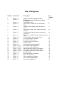
List of Figures
Number TOC Index
Description
1
2
Figure 1.1
Figure 1.2
3
4
Figure 1.3
Figure 1.4
5
Figure 1.5
6
Figure 2.1
7
Figure 2.2
8
Figure 2.3
9
10
11
12
13
14
15
16
17
18
19
20
21
22
23
24
25
Figure 2.4
Figure 2.5
Figure 2.6
Figure 2.7
Figure 2.8
Figure 2.9
Figure 2.10 ,2.11
Figure 2.12,2.13
Figure 2.13,2.14
Figure 2.15,2.16
Figure 2.17,2.18
Figure 2.19
Figure 3.1
Figure 3.2
Figure 3.3
Figure 3.4
Figure 3.5
Output of photon mapping algorithm
Difference between Direct and Indirect
illumination
Soft Shadow Effect
output image without and with Focal Blur
Effect
Output of Participating media and particle
system
direct light, specular light, indirect light and
caustics
Visualization of the four terms evaluated for
each pixel
The four terms added together forming the final
image
4x4 Area Light, location and vectors
Area Light Adaptive samples
Renderable Class design
Event Provides Class Design
Utilities design
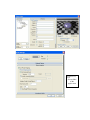
Screen Shots of the Application
Screen Shot of the application
Screen Shot of the application
Photon Mapping Output, Soft Shadows
Focal Blur, Atmospheric Media (Fog)
Sky Sphere Systems, Project Web Site
Download Page
Real Life Particle Simulations
Character Modeling
Facial Animation and games
Laser Lighting Applications
Advertising Application
Page
Number
5
5
5
6
6
10
10
10
14
15
16
17
18
19
20
21
22
23
24
25
26
27
27
27
28
1. Introduction
The use of computer graphics is today growing faster than ever. Especially in the
entertainment industry, but also in the product developing industry in general, where it is
an invaluable tool for construction, design and visualization. Much work has been done
to make the computer-generated images as realistic as possible. The goal is to produce
images that cannot be distinguished from real life.
I. Problem Definition
The project tries to find answers to the following questions
1- Can the computer generate images realistic as real life images?
2- To what extent is the generated image is close to real life images?
By answering these questions we could find that Lighting is the most important factor
in providing live to images that can produce effects like (direct, indirect illumination,
shadows).
II. Existing Algorithms Limitations
There are many available tools like 3d Studio Max, Maya and SoftImage and
modeling Software development kits (SDK) such as Opengl and Directx provides
different solutions for producing computer images.
But these images are not very like to real life because the following problems in
existing Algorithms:
In Software development kits:
1-It does not support real lighting effects based on Ray Tracing such as reflections,
refraction and absorption
2- It don’t care about scene geometrical description
In Existing Modeling Tools
1-It does not support real lighting models because it doesn’t use photon mapping and
global illumination found in real life.
2- It doesn’t support object Media and interior such as (glass, crystal and fluids)
III. Objective
Our project target is to develop a modeling tool that can produce high
realistic images using Different Global illumination algorithms like
(photon mapping, Radiosity)
IV. Project Feature
The Main Features of our project can be summarized in the following
points
Rendering Package
• Fully Feature Ray Tracing Package
• Supporting Most Realistic Images using Photon mapping
• Supporting bump Mapping ,Reflection,Alpha Blending
• High Quality Object Models using Subdivision and Mathematical
Representation
• Soft Shadow Objects
• Supporting Corect Light Model using Radiosity
• Simulating Real life particles (fog) and providing correct Light
transport through physical medias
• Focal blur by simulating the human eye
• Sky and Rainbow Simulation System
• Object Texturing and different Pattern filling (wood ,bozo,cracle)
3D Editor and Modeler
• Easy User interface like most famous CAD Application (3D
Max,MAYA)
• Real time Preview
• Object Management (Selection , Manipulation and Deletion)
• 3D File Import (3ds ,IFS)
• Ramaining Time Rendering Support
Project Development
• The project is released as open source development at
http://photonix.sourceforge.net
• Weekly Updated
V. Previous work
Computer graphics has been an increasingly growing field of computer science.
In 1968, when much of computer graphics was simple raster calculations, Arthur
Apple thought of a new way to render objects. His idea was to trace rays from the
viewer’s eye, through an image plane, and into a scene to discover where objects
were located in a three dimensional world. However, it wasn’t until Turner Whitted
extended this idea into ray tracing in 1980 that the technique became noticed. The
inclusion of both specular reflection and transmission made the algorithm both
versatile and visually appealing. Unfortunately, ray tracing could not handle diffuse
reflections, which is where much of real light comes from.
In 1984 the Radiosity algorithm was created by researchers at Japan’s Fukuyama and
Hiroshima Universities and the United States’ Cornell University. This algorithm,
borrowed from the field of radiative heat transfer, proposed to give everything ray
tracing couldn’t to the graphics field. Mainly, this meant that Radiosity could
calculate diffuse reflection.
In 1986, Kajiya introduced path tracing, an extension to the ray-tracing algorithm that
allowed it to stochastically sample for diffuse reflections. The algorithm worked well,
but noise in the image was a major problem. Also, in 1986 Immel, Cohen, and
Greenberg developed a specular Radiosity program that could simulate specular
reflections. Unfortunately, the excessive time it took to render even a small number of
specular surfaces was discouraging.
In 1987, AT&T introduced a MIMD parallel machine that could render simple scenes
using ray tracing in real time. Since 1988 there has been an explosion in the number
of methods trying to improve either Radiosity or ray tracing, including many attempts
at combining the two. Many attempts have been made at creating real time ray tracing
and radiosity that used parallel machines.
However, in 1996, Henrik Wann Jensen published the first papers on photon
mapping. Photon mapping is a technique that allows the inclusion of both diffuse and
specular reflections without the speed issues or noise issues that arise from radiosity
and ray tracing. Photon mapping uses techniques and ideas from both ray tracing and
radiosity.
We can classify the major solutions into a table illustrating the capability of each
method dealing with BRDF and its complexity.
Category
BRDF and its complexity
Solutions
Radiosity
Diffuse only
Radiosity and
ray tracing
Diffuse and specular (planar surface
only) and single pass
Ray tracing (for
solving the
diffuse
component,
various
techniques are
suggested)
Diffuse and specular (nonplanar
surface) multi pass
Forward statistic ray tracing enables
caustic
Diffuse and specular (nonplanar
surface) deterministic forward ray
tracing
Forward and backward combination
Path mutation in ray tracing
Bi-directional Photon tracing
Hemi-cube Radiosity
Progressive Radiosity
Analytical form-factor
method
Two-pass method
General Two-pass method
Kajia’s Path tracing
Radiance method
Bi-directional path tracing
Metropolis light transfer
method
Photon map method
However, these solutions have common interest in some points. One major thing is important
sampling. To solve a problem using iteration or numerical integration, the variables with
large value should be considered first. It is a kind of importance sampling. The other thing is
error level adjustment. For the radiosity method, it presented as hierarchical or meshing
techniques. In ray tracing, it is represented as ray path level and ray sampling rates.
VI. Project Phases
The project intended to be a modeling tool that helps 3D designers to develop large
scenes and render it with high quality using the new global illumination Algorithms
specified next:
1- Ray tracing : is one of the most popular methods used in 3D computer graphics
to render an image. It works by tracing the path taken by a ray of light through the
scene, and calculating reflection, refraction, or absorption of the ray whenever it
intersects an object in the world
2- Object Models : providing different object model for testing purposes (sphere
,box ,Constructive solid geometry ,Mesh ,Patches ,…)
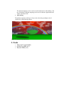
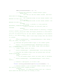
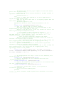
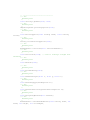
3- photon mapping is a ray tracing technique by which the transport of light from a
light-source through a physical medium such as a glass or a window can be
simulated to produce effects similar to those in real life.
Figure 1.1 Output of photon mapping algorithm
4- Radiosity: The idea was to simulate energy (light) transference from diffuse surfaces.
Diffuse surfaces are surfaces that reflect light equally in all directions – the opposite of a
shiny surface.
Radiosity is quite similar to photon-map based techniques. However, instead of using ray
tracing for final gather, the photons in the photon map are used as light sources and fast
and hardware supported visibility and shadow algorithms are applied.
Figure 1.2 Difference between Direct and Indirect illumination
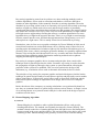
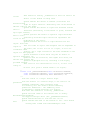
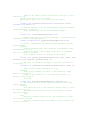
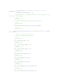
5- Soft shadows: provides an elegant way to simulate florescent and laser light by
not providing a single sharp shadow maps by with providing shadows in realistic
way.
Figure 1.3
Soft Shadow
Effect
6- Focal blur: simulate the human eye by limiting eye near and far distance planes
and providing a focal point where picture is distorted outside this range.
Figure 1.4 output images without and with Focal Blur Effect
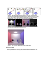
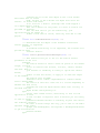
7- Participating Media and Particle systems: by providing correct Light
transport through physical medias .In the same way we interact with space as
media helps simulate light scattering in Natural phenomena (smoke, fire, rain and
fluids)
Figure 1.5 Output of Participating media and particle system
2. Project Details
I. Ray Tracing
Ray tracing is one of the most popular methods used in 3D computer graphics to render an
image. It works by tracing the path taken by a ray of light through the scene, and
calculating reflection, refraction, or absorption of the ray whenever it intersects an object in
the world - hence the name.
For example, starting at a light source, we may trace a ray of light to a surface, which is
transparent but refracts the light beam in a different direction while absorbing some of the
spectrum (and altering the color). From here, the beam may strike another surface, which is
not transparent and so the light undergoes both absorption (further changing the color) and
reflection (changing the direction). Finally, from this second surface it may be reflected
directly into the virtual camera, where its color contributes to the final rendered image.
Ray tracing's popularity stems from its realism over other rendering methods (such as
scanline algorithms); effects such as reflections and shadows, which are difficult to
simulate in other algorithms, follow naturally from the ray tracing algorithm. The main
drawback of ray tracing is that it can be an extremely slow process, due mainly to the large
numbers of light rays which need to be traced, and the larger number of potentially
complicated intersection calculations between light rays and geometry (the result of which
may lead to the creation of new rays). Since very few of the potential rays of light emitted
from light sources might end up reaching the camera, a common optimization is to trace
hypothetical rays of light in the opposite direction. That is, a ray of light is traced starting
from the camera into the scene, and back through interactions with geometry, to see if it
ends up back at a light source. This is usually referred to as backwards ray tracing.
Nonetheless, since its first use as a graphics technique by Turner Whitted in 1980, much
research has been done on acceleration schemes for ray tracing; many of these focus on
speeding up the determination of whether a light ray has intersected an arbitrary piece of
geometry in the scene, often by storing the geometric database in a spatially organised data
structure. Ray tracing has also shown itself to be very versatile, and in the last decade ray
tracing has been extended to global illumination rendering methods such as photon
mapping and Metropolis light transport.
Ray tracing in computer graphics derives its name and principles from a much older
technique used for lens design since the 1900s. Geometric ray tracing is used to describe
the propagation of light rays through a lens system or optical instrument, allowing the
properties of the system to be modelled. This is used to optimise the design of the
instrument (e.g. to minimise effects such as chromatic aberration) before it is built.
The principles of ray tracing for computer graphics and optical design are similar, but the
technique in optical design usually uses much more rigorous and physically correct models
of how light behaves. In particular, optical effects such as dispersion, diffraction and the
behaviour of optical coatings are important in lens design, but are less so in computer
graphics.
Before the advent of the computer, ray tracing calculations were performed by hand, but
now they are common features of optical design software such as Zemax. A simple version
of ray tracing known as ray transfer matrix analysis is often used in the design of optical
resonators used in lasers.
II. Photon Mapping Algorithm
A) General
Photon Mapping is a method to achieve global illumination effects, such as color
bleeding and caustics. The method was originally developed by Jensen [JEN96]. The
method is based on the idea of emitting photons from the light sources and letting them
bounce around in the scene until absorption. This emission takes place before any actual
rendering is done. Photons hitting scene geometry are stored to be used later during
rendering. Many photons are needed to get good image quality, typically 100.000 –
1.000.000 photons depending on the specific scene. The collections of photons are called
a photon map. Normal ray tracing methods are combined with the photon map during
rendering. The density of photons in the neighborhood of a specific query point is used to
get an irradiance estimate during rendering, and this value is used as an approximation
instead of performing a costly Monte Carlo integration.
Photon Mapping can be divided into three consecutive steps, each of which is described
in the subsequent subsections.
• Photon Tracing
• Photon Map Sorting
• Rendering
B) Photon Tracing
Each light source emits photons which are traced through the scene. A photon hitting a
surface can be reflected, transmitted or absorbed. Russian roulette is used to determine
which of these three events should occur, with probabilities based on the material
properties. A photon path is terminated when it is absorbed. Photons hitting diffuse
surfaces are stored for later use, each photon emitted from a light source can therefore be
stored many times during its path through the scene (hitting several diffuse surfaces). The
collection of stored photons is the global photon map.
An additional caustics photon map may also be created. This photon map only stores
photons hitting diffuse surfaces if they have been reflected or transmitted from a specular
surface.
The following information is stored for each photon.
• Photon position
• Photon flux
• Incident direction
C) Photon Map Sorting
All photons created during photon tracing are in this step sorted to allow fast lookups
during the rendering step. Jensen [JEN96] uses a balanced kd-tree since it is a compact
representation which allows a non-uniform distribution of photons in the scene. The
global photons and the caustics photons are stored into separate photon maps.
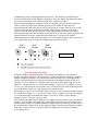
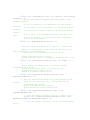
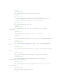
D) Rendering
Four terms are evaluated and added together to get the color of each pixel in the image.
• Direct light
• Specular light
• Indirect light
• Caustics
Figure A1.a illustrates how the direct light term is calculated. The red arrow represents a
primary ray sent from the camera. The black arrows represent shadow rays sent from the
intersection point towards all light sources.
Figure A1.b illustrates how specular reflection and transmission are calculated. The blue
object is both diffuse and specular. Reflected rays are sent to collect illumination in the
specular direction.
Figure A1.c illustrates how indirect light from other surfaces is calculated with a Monte
Carlo integration over the hemisphere. Often, hundreds or thousands of gathering rays are
needed to get an acceptable integration estimate with low variance. This large number of
rays can be reduced with importance sampling methods. It is also possible to reduce the
number of Monte Carlo integrations using Ward’s interpolation scheme
[WAR88][WAR92].
The Monte Carlo gathering rays hitting geometry would normally generate secondary
gathering rays, which in turn would generate third generation rays, etc. We can get an
irradiance value from the global photon map instead of generating secondary gathering
rays. The position and incident direction where a gathering ray hits geometry is used to
query the photon map for an irradiance value. The result we get from such a query
contains both direct and indirect light as well as caustics effects.
Figure A1.d illustrates how caustics are added to the solution by querying the caustics
photon map at the intersection point.
A ‘photon density’ calculation is used to estimate an irradiance value for both the global
photon map and the caustics photon map. This density calculation can be imagined as
expanding a sphere around the query point until enough photons have been collected or
until a maximum radius is reached. Typically, 50-500 photons are used. The density is
then calculated as total photon power divided by the squared radius. The volume is not
used since the photons found are most likely located on a surface, i.e. the expanding
sphereforms a circle on the surface.
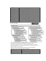
Figure A2 shows a rendering of the Cornell box where each of the four light
contributions is rendered as a separate image. Figure A3 shows the four terms added
together forming the final image.
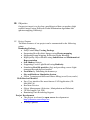
Figure 2.1 – Illustration of the four terms evaluated for each pixel. From left to right,
direct light, specular light, indirect light and caustics. The red arrow represents a primary
ray sent from the camera. The two ellipses are objects in the scene. The blue object is
both diffuse and specular. The yellow circles represent two light sources.
Figure 2.2 – Visualization of the four terms evaluated for each pixel. From left to right,
direct light, specular light, indirect light and caustics.
Figure 2.3 – The four terms added together forming the final image.
E) Mathematical Basis
Bi-directional path tracing connects a single gathering walk to a single shooting walk.
However, if the effects of a shooting walk, for instance, could be stored, then when a
new gathering walk is computed, it could be connected to all of them simultaneously.
This is exactly what Jensen [19, 18, and 20] proposed, also giving the definition of a
data structure, called the photon-map which can efficiently store the effects of many
shooting walks.
A photon map is a collection of photon hits generated in the shooting phase of the
algorithm. The photon-map is organized in a kd-tree to support efficient retrieval. A
photon hit is stored with the power of the photon on different wavelengths, position,
and direction of arrival and with the surface normal.
The gathering phase is based on the following approximation of the transport
operator:
Where ΔΦ i (x, ω i ) is the power of a photon landing at the surface ΔA from direction
ω i′ .The ΔΦ and Δ A quantities are approximated from the photons in the
r
neighborhood of x in the following way. A sphere centered around
until it contains n photons. If at this point the radius of the sphere is
r
x
r
is extended
, then the
intersected surface area is ΔA = πr
• Photon Shooting
struct photon
{
float x, y, z; // where this photon was stored
char power; char φ , θ ; // its power, and where
it came from
short cd; // the cutting dimension (kd tree)
}
diffuse pointShoot()
np = 0; p = lightSource();
while (not enough photons)
{
d = randomDirection();
shoot photon in direction d to get pos
np += 1;
}
2
Scale power by
store photon at pos with power and direction
• Computing Reflected Radiance
We want to the reflected radiance at x in the outgoing direction w
• In the photon map, we find a photon p close to x and we know it came
from
the direction and it has some differential flux.
We know the BRDF fr at point x.
The reflected radiance
is approximated as
where r is the distance to the farthest photon p.
• kd-trees
Dimension of data is k (but common to say k-d tree of dimension 3 instead of 3dtree).
Kd-trees are binary trees
Designed to handle spatial data in a simple way
For n points, O (n) space, O (log n) height (if balanced), supports range and
nearest- neighbor queries.
Node consists of
• Two child pointers,
• Satellite information (such as name).
• A key: Either a single float representing a coordinate value, or a pair of
floats (representing a dimension of a rectangle)
•
Basic Idea Behind kd-trees
Construct a binary tree
At each step, choose one of the coordinate as a basis of dividing the rest of the
points
For example, at the root, choose x as the basis
• Like binary search trees, all items to the left of root will have the xcoordinate less than that of the root
• All items to the right of the root will have the x-coordinate greater than (or
equal to) that of the root
Choose y as the basis for discrimination for the root's children
And choose x again for the root's grandchildren
Note: Equality (corresponding to right child) is signicant
Assume points are sorted on both x and y in a composite array S,S[x] corresponds
to a list of points sorted by x.The Algorithm of building the tree is as follows
KDNode buildTree(SortedArray S , int cd )
{
if (S.empty()) return null;
else if S.singleton() return new KDNode(S[x][0],cd);
else
{
m = median ( S , cd ) // median ( cut t ing dimens ion )
left = leftPoints (S , cd ) ; right = S-left;
t = new KDNode(m);
t.left= buildTree (left , cd+1);
t.right= buildTree( right, cd+1);
return t
}
}
• T(n) = kn + 2T(n=2), so the algorithm takes O(n log n) time.
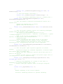
III. Soft Shadows
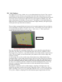
Area light sources occupy a finite, one- or two-dimensional area of space. They can cast
soft shadows because an object can partially block their light. Point sources are either
totally blocked or not blocked. It is approximated as an array of point light sources spread
out over the area occupied by the light. The array-effect applies to shadows only. The
object's illumination is still that of a point source. The intensity of each individual point
light in the array is dimmed so that the total amount of light emitted by the light is equal
to the light color specified in the declaration.
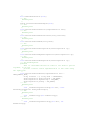
The area light command defines the location, the size and orientation of the area light as
well as the number of lights in the light source array. The location vector is the centre of
a rectangle defined by the two vectors <Axis_1> and <Axis_2>. These specify the
lengths and directions of the edges of the light.
Figure 2.4
Since the area lights are rectangular in shape these vectors should be perpendicular to
each other. The larger the size of the light the thicker the soft part of shadows will be.
The integers Size_1 and Size_2 specify the number of rows and columns of point sources
of the. The more lights you use the smoother your shadows will be but the longer they
will take to render.
An interesting effect can be created using a linear light source. Rather than having a
rectangular shape, a linear light stretches along a line sort of like a thin fluorescent tube.
To create a linear light just create an area light with one of the array dimensions set to 1.
The jitter command is optional. When used it causes the positions of the point lights in
the array to be randomly jittered to eliminate any shadow banding that may occur. The
jittering is completely random from render to render and should not be used when
generating animations.
The adaptive command is used to enable adaptive sampling of the light source. By
default the algorithm calculates the amount of light that reaches a surface from an area
light by shooting a test ray at every point light within the array. As you can imagine this
is very slow. Adaptive sampling on the other hand attempts to approximate the same
calculation by using a minimum number of test rays. The number specified after the
keyword controls how much adaptive sampling is used. The higher the number the more
accurate your shadows will be but the longer they will take to render.
When performing adaptive sampling it starts by shooting a test ray at each of the four
corners of the area light. If the amount of light received from all four corners is
approximately the same then the area light is assumed to be either fully in view or fully
blocked. The light intensity is then calculated as the average intensity of the light
received from the four corners. However, if the light intensity from the four corners
differs significantly then the area light is partially blocked. The area light is split into four
quarters and each section is sampled as described above. This allows to rapidly
approximating how much of the area light is in view without having to shoot a test ray at
every light in the array. Visually the sampling goes like shown below.
Figure 2.5
While the adaptive sampling method is fast (relatively speaking) it can sometimes
produce inaccurate shadows. The solution is to reduce the amount of adaptive sampling
without completely turning it off. The number after the adaptive keyword adjusts the
number of times that the area light will be split before the adaptive phase begins. For
example if you use adaptive 0 a minimum of 4 rays will be shot at the light. If you use
adaptive 1 a minimum of 9 rays will be shot (adaptive 2 gives 25 rays, adaptive 3 gives
81 rays, etc). Obviously the more shadow rays you shoot the slower the rendering will be
so you should use the lowest value that gives acceptable results.
The number of rays never exceeds the values you specify for rows and columns of points.
For example area light x, y, 4, 4 specifies a 4 by 4 array of lights. If you specify adaptive
3 it would mean that you should start with a 9 by 9 array. In this case no adaptive
sampling is done. The 4 by 4 array is used.
The circular command has been added to area lights in order to better create circular soft
shadows. With ordinary area lights the pseudo-lights are arranged in a rectangular grid
and thus project partly rectangular shadows around all objects, including circular objects.
By including the circular tag in an area light, the light is stretched and squashed so that it
looks like a circle: this way, circular or spherical light sources are better simulated.
A few things more:
•
•
•
Circular area lights can be ellipses: the AXIS_1_VECTOR and
AXIS_2_VECTOR define the shape and orientation of the circle; if the vectors
are not equal, the light source is elliptical in shape.
Rectangular artifacts may still show up with very large area grids.
The area of a circular light is roughly 78.5 per cent of a similar size rectangular
area light. Increase your axis vectors accordingly if you wish to keep the light
source area constant.
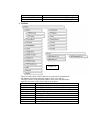
• 3D Editor and Modeler Engine
The 3D Editor phase is the most important phase in the project because it helps the
users to interact with the application and produce output generated using the global
illumination algorithms specified above
The 3D Engine we made to build our 3d modeler above it mainly consists of
1. Renderables
Figure 2.6
Which they are the set of classes that can be rendered on the screen using
different Graphics platforms Like (Opengl & DirectX)
The figure shown is the hierarchy chart of base class and inheritance
And here are some of the classes and its description:
Class Name
Description
IRenderable
Base Interface For renderable objects
GUIWnd
Base Interface For regular window
GUIButton
Representation of a reular button
GUIWindow
Representation of a regular window
BoxMesh
Representation of bounding box
ConeMesh
Representation of cone object
GridMesh
IRendering
RenderWindow
D3D8RenderWindow
Win32Window
RenderTexture
GLRenderTexture
LineMesh
Mesh
MeshBox
SceneNode
SphereMesh
TorusMesh
SuperEllipsoid
2. Event Providers
Representation of grid object
Base Interface For buffer objects
Base Interface For window buffer objects
DirectX Specific implementation
OpenGL Specific implementation
a texture that can be rendered to it
Specific implementation of render texture
Representation of line object
Representation of mesh object
Representation of box object
Base node in the hierarchy tree
Representation of sphere object
Representation of torus object
Representation of SuperEllipsoid object
Figure 2.7
This is the part where the events of the operating system are handled and
processed by the engine classes like keyboard and mouse input
The design is based on the idea of client server activity where some of the
classes described above work as provider of the service and others work as
Receiver of the service or event.
The figure shown is the hierarchy chart of base class and inheritance
And here are some of the classes and its description:
Class Name
Description
IEventProvider
Base interface for event providing
FrameProvider
Base interface for frame providing
IMessageProvider
Base interface for message passing
IWindowMessageProvider Base interface for window message passing
IGenericMessageProvider Base interface for generic message passing
IMouseProvider
Base interface for mouse events providing
3. Utilities
Figure 2.8
These are some utility classes that have a great help in mathematical
calculations and object texturing support, view port, camera …
The figure shown is the hierarchy chart of base class and inheritance
And here are some of the classes and its description:
Class Name
Description
Texture
Base implementation for texture
D3D8Texture
DirectX Specific Implementation for Texture object
GLTexture
OpenGL Specific Implementation for Texture object
CViewPort
View Port Manager
CachedMatrix
Caching of the original 4x4 Matrix
Camera
Virtual Camera Manager
D3D8Driver
DirectX Driver Enumerator
Light
Virtual Light Manager
Material
Virtual Material Manager
Matrix4
Quaternion
STDImage
Scene
SceneSelector
Vector2
Vector3
Vector4
MTool
MTranslationTool
MRotationTool
MScaleTool
•
4x4 Matrix Calculator
Quaternion Implementation
Base Image Implementation
Core of the rendering
Mouse interactor with scene to support selection
2d vector helper function
3d vector helper function
4d vector helper function
Base class for selection tools
Tool that can do interactive translation
Tool that can do interactive rotation
Tool that can do interactive scale
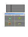
Screen Shots
Figure 2.9: Screen Shots of the Application
Figure 2.10,
2.11
Screen Shot
of the
application
Figure 2.12 ,2.13
Screen Shot of the
application
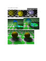
Screen Shots of the OutPut
Pigment
Normals
Figure 2.13 : Photon Mapping Output
Figure 2.14 : Soft Shadows
Reflection
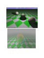
Figure 2.15: Focal Blur
Figure 2.16: Atmospheric Media (Fog)
Figure 2.17 Sky Sphere Systems
Figure 2.18 :Project Web Site
Figure2.19 Download Page
Applications
•
•
•
•
•
•
•
•
Virtual reality
Particle Real life Simulation(fog , fire,smoke ..etc)
Character modeling and animation
Entertainment movies
Games
Physics laser lighting applications
CAD/CAM designing
Advertising
•
Virtual reality
As the photon mapping algorithm reach the computer graphics to high
degree of reality so we can use computers to simulate real environments
and real scenes.
•
Particle Real life Simulation(fog , fire,smoke ..etc)
This on of the main applications of the photon mapping technique since
smoke and fires are the hardest particle system simulations and photon
mapping ease the modeling of these systems.
•
Figure 3.1 Real Life Particle Simulations
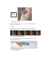
Character modeling and animation
Photon mapping reach a reality in images of human skin using a technique
called Digital Face Cloning invented by Henrik Wann Jensen and next
figure indicate the rendering of human face by photon mapping techniques
Figure 3.2
Character
Modeling
•
Entertainment movies
The will no need for directors to make a lot of tricks because computers will
generate a lot of real scenes.
•
Games
The animated characters in the current games will be soon as real as the
people see them in real world, computer will generate the parson from his
model as real as he appear.
Figure 3.3 Facial Animation and games
• Physics laser lighting applications
The photon mapping technique can easily simulate the laser lighting effect as
shown in the picture bellow.
Figure 3.4 Laser Lighting Applications
• CAD/CAM designing
•
The photon mapping can be used to model architectures and building. The
new technique of photon mapping can be used in famous applications like
3dmax and AutoCAD
Advertising
The photon mapping technique will give the advertising techniques alt of
variations for announcing prducts.
Figure 3.5 Advertising Application
3- Tools
o Microsoft Visual Studio
o nVidia Cg SDK (6.0)
o DirectX SDK (9.0)
4-Sample Source Code From The Project
1-Render Operation
#ifndef _RenderOperation_H__
#define _RenderOperation_H__
#include "ColourValue.h"
#include "Material.h"
//#include "isaveload.h"
class RenderOperation {
public:
enum OpType {
OT_POINT_LIST,
OT_LINE_LIST,
OT_LINE_STRIP,
OT_TRIANGLE_LIST,
OT_TRIANGLE_STRIP,
OT_TRIANGLE_FAN
};
/** Vertex options - which elements to include.
@remarks
Vertices must include their elements in the following
order:
position, normal, texture co-ords (1-3 dimensions, 1-4
sets),
diffuse colour, specular colour. Only position is
mandatory,
although at least ONE OF the following should be
specified,
even if ambient light on flat coloured objects only is
being used.
*/
enum VertexOptions {
/// vertex normals included (for lighting)
VO_NORMALS = 1,
/// at least one set of texture coords (exact number
specified in class)
VO_TEXTURE_COORDS = 2,
/// Vertex colours - diffuse
VO_DIFFUSE_COLOURS = 4,
/// Vertex colours - specular
VO_SPECULAR_COLOURS = 8,
};
/** Vertex blend info */
struct VertexBlendData
{
unsigned short matrixIndex;
Real blendWeight;
};
// true to use pIndexes to reference individual lines/triangles
rather than embed. Allows vertex reuse.
bool useIndexes;
/// Number of vertices (applies to all components)
unsigned int numVertices;
// No memory allocation here,
// assumed that all pointers are pointing
// elsewhere e.g. model class data
/** Pointer to list of vertices (float {x, y z} * numVertices).
@remarks
If useIndexes is false each group of 3 vertices
describes a face (anticlockwise winding) in
trianglelist mode.
*/
Real* pVertices;
/// The 'Stride' between sets of vertex data. 0 indicates data
is packed with no gaps.
unsigned short vertexStride;
/// Optional vertex normals for vertices (float {x, y, z} *
numVertices).
Real* pNormals;
/// The 'Stride' between sets of normal data. 0 indicates data
is packed with no gaps.
unsigned short normalStride;
/** Optional texture coordinates for vertices (float {u, [v],
[w]} * numVertices).
@remarks
There can be up to 8 sets of texture coordinates, and
the number of components per
vertex depends on the number of texture dimensions (2
is most common).
*/
Real* pTexCoords[MAX_TEXTURE_COORD_SETS];
/// The 'Stride' between each set of texture data. 0 indicates
data is packed with no gaps.
unsigned short texCoordStride[MAX_TEXTURE_COORD_SETS];
/// Number of groups of u,[v],[w].
int numTextureCoordSets;
/** Number of dimensions in each corresponding texture
coordinate set.
@note
There should be 1-4 dimensions on each set.
*/
int numTextureDimensions[MAX_TEXTURE_COORD_SETS];
/// Optional pointer to a list of diffuse vertex colours (32bit RGBA * numVertices).
RGBA* pDiffuseColour;
/// The 'Stride' between sets of diffuse colour data. 0
indicates data is packed with no gaps.
unsigned short diffuseStride;
/// Optional pointer to a list of specular vertex colours (32bit RGBA * numVertices)
RGBA* pSpecularColour;
/// The 'Stride' between sets of specular colour data. 0
indicates data is packed with no gaps.
unsigned short specularStride;
/** Pointer to a list of vertex indexes describing faces (only
used if useIndexes is true).
@note
Each group of 3 describes a face (anticlockwise winding
order).
*/
unsigned short* pIndexes;
/// The number of vertex indexes (must be a multiple of 3).
unsigned int numIndexes;
/// Flags indicating vertex types
int vertexOptions;
/// The type of rendering operation.
OpType operationType;
Material * mMaterial;
int References;
RenderOperation();
void AddRef();
void Free();
//void DoSerialize(ISaveLoad * archive);
};
/* Example usage (camera at (0,0,0) pointing down -Z (lookAt(0,0,300))
RenderOperation ro;
float vertexData[9] = {100,
*/
#endif
0, -300,
0, 200, -300,
-100,
0, -300 };
float normalData[9] = { 0, 0, 1,
0, 0, 1,
0, 0, 1};
ro.operationType = RenderOperation::OT_TRIANGLE_LIST;
ro.numVertices = 3;
ro.useIndexes = false;
ro.vertexOptions = RenderOperation::VO_NORMAL;
ro.pVertices = vertexData;
ro.pNormals = normalData;
mDestRenderSystem->_render(ro);
2- Render System
// RenderSystem.h: interface for the RenderSystem class.
//
//////////////////////////////////////////////////////////////////////
#ifndef __RENDERSYSTEM_H
#define __RENDERSYSTEM_H
#include
#include
#include
#include
"rendertexture.h"
"Material.h"
"GSMIncludes.h"
"RenderOperation.h"
/// Enum describing the ways to generate texture coordinates
enum TexCoordCalcMethod
{
/// No calculated texture coordinates
TEXCALC_NONE,
/// Environment map based on vertex normals
TEXCALC_ENVIRONMENT_MAP,
/// Environment map based on vertex positions
TEXCALC_ENVIRONMENT_MAP_PLANAR,
TEXCALC_ENVIRONMENT_MAP_REFLECTION,
TEXCALC_ENVIRONMENT_MAP_NORMAL
};
enum StencilOperation
{
SOP_KEEP,
SOP_ZERO,
SOP_REPLACE,
SOP_INCREMENT,
SOP_DECREMENT,
SOP_INVERT
};
#include "supportedinterfaces.h"
//class CViewPort;
class RenderSystem
{
:public FrameProvider
public:
RenderSystem();
virtual ~RenderSystem();
/** Returns the name of the rendering system.
*/
virtual const CString& getName(void) const = 0;
/** Returns the details of this API's configuration options
@remarks
Each render system must be able to inform the world
of what options must/can be specified for it's
operation.
@par
These are passed as strings for portability, but
grouped into a structure (_ConfigOption) which includes
both options and current value.
@par
Note that the settings returned from this call are
affected by the options that have been set so far,
since some options are interdependent.
@par
This routine is called automatically by the default
configuration dialogue produced by Root::showConfigDialog
or may be used by the caller for custom settings dialogs
@returns
A 'map' of options, i.e. a list of options which is also
indexed by option name.
*/
virtual CMapStringToOb& getConfigOptions(void) = 0;
user) in
/** Sets an option for this API
@remarks
Used to confirm the settings (normally chosen by the
order to make the renderer able to initialise with the
settings as required.
This may be video mode, D3D driver, full screen /
windowed etc.
Called automatically by the default configuration
dialog, and by the restoration of saved settings.
These settings are stored and only activated when
RenderSystem::initialise or RenderSystem::reinitialise
are called.
@par
If using a custom configuration dialog, it is advised
that the
caller calls RenderSystem::getConfigOptions
again, since some options can alter resulting from a
selection.
@param
name The name of the option to alter.
@param
value The value to set the option to.
*/
virtual void setConfigOption(const CString &name, const CString
&value) = 0;
/** Validates the options set for the rendering system,
returning a message if there are problems.
@note
If the returned string is empty, there are no problems.
*/
virtual CString validateConfigOptions(void) = 0;
/** Start up the renderer using the settings selected
(Or the defaults if none have been selected).
@remarks
Called by Root::setRenderSystem. Shouldn't really be
called
directly, although this can be done if the app wants
to.
saves
@param
autoCreateWindow If true, creates a render window
automatically, based on settings chosen so far. This
an extra call to RenderSystem::createRenderWindow
for the main render window.
@par
If an application has more specific window
requirements,
however (e.g. a level design app), it should specify
false
for this parameter and do it manually.
@returns
A pointer to the automatically created window, if
requested, otherwise null.
*/
virtual RenderWindow* initialise(bool autoCreateWindow);
/** Restart the renderer (normally following a change in
settings).
*/
virtual void reinitialise(void) = 0;
/** Shutdown the renderer and cleanup resources.
*/
virtual void shutdown(void){};
/** Registers a FrameListener which will be called back every
frame.
@remarks
A FrameListener is a class which implements methods
which
will be called during me's automatic rendering loop
(started
with RenderSystem::startRendering).
@par
See the FrameListener class for more details on the
specifics.
It is imperitive that the instance passed to this
method is
not destroyed before iether the rendering loop ends, or
the
class is removed from the listening list using
removeFrameListener.
@see
FrameListener
*/
//^
virtual void addFrameListener(FrameListener* newListener);
/** Removes a FrameListener from the list of listening classes.
*/
//^
virtual void removeFrameListener(FrameListener*
oldListener);
/** Starts / restarts the automatic rendering cycle.
@remarks
This method begins the automatic rendering of the
scene.
This method will NOT RETURN until the rendering
cycle is halted.
@par
During rendering, any FrameListener classes registered
using
addFrameListener will be called back for each frame
that is to be rendered,
These classes can tell GSM to halt the rendering if
required,
which will cause this method to return.
@par
Note - users of the GSM library do not have to use this
automatic rendering loop. It is there as a convenience
and is most
useful for high frame rate applications e.g. games. For
applications that
don't need to constantly refresh the rendering targets
(e.g. an editor
utility), it is better to manually refresh each render
target only when
required by calling RenderTarget::update.
@par
This frees up the CPU to do other things in between
refreshes, since in
this case frame rate is less important.
*/
virtual void startRendering(void);
/** Sets the colour & strength of the ambient (global
directionless) light in the world.
*/
virtual void setAmbientLight(float r, float g, float b) = 0;
/** Sets the type of light shading required (default =
Gouraud).
*/
virtual void setShadingType(ShadeOptions so) = 0;
/** Sets the type of texture filtering used when rendering
@remarks
This method sets the kind of texture filtering applied
when rendering textures onto
primitives. Filtering covers how the effects of
minification and magnification are
disguised by resampling.
@param
fo The type of filtering to apply. The options are
described in
TextureFilterOptions
*/
virtual void setTextureFiltering(TextureFilterOptions fo) = 0;
/** Sets whether or not dynamic lighting is enabled.
@param
enabled If true, dynamic lighting is performed on
geometry with normals supplied, geometry without
normals will not be displayed. If false, no lighting is
applied and all geometry will be full brightness.
*/
virtual void setLightingEnabled(bool enabled) = 0;
/** Creates a new rendering window.
@remarks
This method creates a new rendering window as specified
by the paramteters. The rendering system could be
responible for only a single window (e.g. in the case
of a game), or could be in charge of multiple ones (in
the
case of a level editor). The option to create the
window
as a child of another is therefore given.
This method will create an appropriate subclass of
RenderWindow depending on the API and platform
implementation.
@par
After creation, this window can be retrieved using
getRenderTarget().
@param
name The name of the window. Used in other methods
later like setRenderTarget and getRenderWindow.
@param
width The width of the new window.
@param
height The height of the new window.
@param
colourDepth The colour depth in bits per pixel.
Only applicable if fullScreen = true
@param
fullScreen Specify true to make the window full screen
without borders, title bar or menu bar.
@param
left The x position of the new window. Only applicable
if fullScreen is false. Units are relative to the
parent window
if applicable, otherwise they are in screen
coordinates.
@param
top The y position of the new window.
@param
depthBuffer If true, a depth buffer will be assigned to
this window.
@param
parentWindowHandle Should be null if this window is to
be
stand-alone. Otherwise, specify a pointer to a
RenderWindow
which represents the parent window.
*/
virtual RenderWindow* createRenderWindow(const CString &name,
int width, int height, int colourDepth,
bool fullScreen, int left = 0, int top = 0, bool
depthBuffer = true,
HWND parentWindowHandle = 0) = 0;
/** Creates and registers a render texture object.
@param name
The name for the new render texture. Note that
names must be unique.
@param width
The requested width for the render texture. See
Remarks for more info.
@param height
The requested width for the render texture. See
Remarks for more info.
@returns
On succes, a pointer to a new platformdependernt, RenderTexture-derived
class is returned. On failiure, NULL is
returned.
@remarks
Because a render texture is basically a wrapper
around a texture object,
the width and height parameters of this method
just hint the preferred
size for the texture. Depending on the hardware
driver or the underlying
API, these values might change when the texture
is created.
*/
//&
virtual RenderTexture * createRenderTexture( const String &
name, int width, int height ) = 0;
/** Attaches the passed render target to the render system.
*/
//^
virtual void attachRenderTarget( RenderTarget &target );
/** Returns a pointer to the render target with the passed
name, or NULL if that
render target cannot be found.
*/
//^
virtual RenderTarget * getRenderTarget( const String &name
);
/** Detaches the render target with the passed name from the
render system and
returns a pointer to it.
@note
If the render target cannot be found, NULL is returned.
*/
//^
virtual RenderTarget * detachRenderTarget( const String
&name );
/** Returns a description of an error code.
*/
virtual CString getErrorDescription(long errorNumber) = 0;
/** Defines whether or now fullscreen render windows wait for
the vertical blank before flipping buffers.
@remarks
By default, all rendering windows wait for a vertical
blank (when the CRT beam turns off briefly to move
from the bottom right of the screen back to the top
left) before flipping the screen buffers. This ensures
that the image you see on the screen is steady. However
it restricts the frame rate to the refresh rate of
the monitor, and can slow the frame rate down. You can
speed this up by not waiting for the blank, but
this has the downside of introducing 'tearing'
artefacts where part of the previous frame is still displayed
as the buffers are switched. Speed vs quality, you
choose.
@note
Has NO effect on windowed mode render targets. Only
affects fullscreen mode.
@param
enabled If true, the system waits for vertical blanks quality over speed. If false it doesn't - speed over quality.
*/
void setWaitForVerticalBlank(bool enabled);
/** Returns true if the system is synchronising frames with the
monitor vertical blank.
*/
bool getWaitForVerticalBlank(void);
// ----------------------------------------------------------------------//
Internal Rendering Access
// All methods below here are normally only called by other GSM
classes
// They can be called by library user if required
// ----------------------------------------------------------------------/**
Adds a light to the renderers list of active lights
This method should not be called directly by user
processes - this is adding a light at the rendering
level. User processes should add lights using the
SceneNode attachLight method
*/
virtual void _addLight(Light *lt) = 0;
/**
Removes a light from the renderers list.
As with RenderSystem::_addLight
this method is for use internally, not by user processes.
See SceneNode for user-level light maintenance.
*/
virtual void _removeLight(Light *lt) = 0;
/** Modifies a light in the renderer.
Modifies a light which has already been added using
_addLight.
*/
virtual void _modifyLight(Light* lt) = 0;
/**
Clears all the lights from the renderer
As with RenderSystem::_addLight
this method is for use internally, not by user processes.
See SceneManager for user-level light maintenance.
*/
virtual void _removeAllLights(void) = 0;
/**
Saves the current rendering state
Stores the current rendering state on the
render state stack. The state may then be altered
and restored back to it's previous state using
RenderSystem::_popRenderState. Used internally by me
to manage changes like model/view matrices, active
materials/textures without having to repecify them
every time.
*/
virtual void _pushRenderState(void) = 0;
/** Restores the render state to a previous state. */
virtual void _popRenderState(void) = 0;
/** Sets the world transform matrix. */
virtual void _setWorldMatrix(const Matrix4 &m) = 0;
/** Sets multiple world matrices (vertex blending). */
virtual void _setWorldMatrices(const Matrix4* m, unsigned short
count);
/** Sets the view transform matrix */
virtual void _setViewMatrix(const Matrix4 &m) = 0;
/** Sets the projection transform matrix */
virtual void _setProjectionMatrix(const Matrix4 &m) = 0;
/** Utility function for setting all the properties of a
texture unit at once.
This method is also worth using over the individual texture
unit settings because it
only sets those settings which are different from the
current settings for this
unit, thus minimising render state changes.
*/
virtual void _setTextureUnitSettings(int texUnit,
Material::TextureLayer& tl);
/** Turns off a texture unit. */
virtual void _disableTextureUnit(int texUnit);
/** Sets the surface properties to be used for future
rendering.
This method sets the the properties of the surfaces of
objects
properties
to be rendered after it. In this context these surface
are the amount of each type of light the object reflects
(determining
it's colour under different types of light), whether it
emits light
itself, and how shiny it is. Textures are not dealt with
here,
see the _setTetxure method for details.
This method is used by _setMaterial so does not need to be
called
direct if that method is being used.
@param ambient The amount of ambient (sourceless and
directionless)
light an object reflects. Affected by the colour/amount of
ambient light in the scene.
@param diffuse The amount of light from directed sources
that is
reflected (affected by colour/amount of point, directed and
spot light sources)
@param specular The amount of specular light reflected.
This is also
affected by directed light sources but represents the
colour at the
highlights of the object.
@param emissive The colour of light emitted from the
object. Note that
this will make an object seem brighter and not dependent on
lights in
the scene, but it will not act as a light, so will not
illuminate other
objects. Use a light attached to the same SceneNode as the
object for this purpose.
@param shininess A value which only has an effect on
specular highlights (so
specular must be non-black). The higher this value, the
smaller and crisper the
specular highlights will be, imitating a more highly
polished surface.
This value is not constrained to 0.0-1.0, in fact it is
likely to
be more (10.0 gives a modest sheen to an object).
*/
virtual void _setSurfaceParams(const ColourValue &ambient,
const ColourValue &diffuse, const ColourValue &specular,
const ColourValue &emissive, Real shininess) = 0;
/**
Sets the status of a single texture stage.
Sets the details of a texture stage, to be used for all
primitives
rendered afterwards. User processes would
not normally call this direct unless rendering
primitives themselves - the SubEntity class
is designed to manage materials for objects.
Note that this method is called by _setMaterial.
@param unit The index of the texture unit to modify.
Multitexturing hardware
can support multiple units (see _getNumTextureUnits)
@param enabled Boolean to turn the unit on/off
@param texname The name of the texture to use - this should
have
already been loaded with TextureManager::load.
*/
virtual void _setTexture(int unit, bool enabled, const CString
&texname) = 0;
/** Returns the number of texture units the current output
hardware supports.
For use in rendering, this determines how many texture
units the
textures
are available for multitexturing (i.e. rendering multiple
in a single pass). Where a Material has multiple texture
layers,
where
it will try to use multitexturing where available, and
it is not available, will perform multipass rendering to
achieve the same effect.
*/
virtual int _getNumTextureUnits(void) = 0;
/**
Sets the texture coordinate set to use for a texture unit.
Meant for use internally - not generally used directly by
apps - the Material and TextureLayer
classes let you manage textures far more easily.
@param unit Texture unit as above
@param index The index of the texture coordinate set to use.
*/
virtual void _setTextureCoordSet(int unit, int index) = 0;
/**
Sets a method for automatically calculating texture
coordinates for a stage.
Should not be used by apps - for use by me only.
@param unit Texture unit as above
@param m Calculation method to use
*/
virtual void _setTextureCoordCalculation(int unit,
TexCoordCalcMethod m) = 0;
/** Sets the texture blend modes from a TextureLayer record.
Meant for use internally only - apps should use the
Material
and TextureLayer classes.
@param unit Texture unit as above
@param bm Details of the blending mode
*/
virtual void _setTextureBlendMode(int unit, const
LayerBlendModeEx& bm) = 0;
/** Sets the texture filtering type for a texture unit.*/
virtual void _setTextureLayerFiltering(int unit, const
TextureFilterOptions texLayerFilterOps) = 0;
unit.*/
/** Sets the maximal anisotropy for the specified texture
virtual void _setTextureLayerAnisotropy(int unit, int
maxAnisotropy) = 0;
/** Sets the maximal anisotropy.*/
virtual void _setAnisotropy(int maxAnisotropy) = 0;
/** Sets the texture addressing mode for a texture unit.*/
virtual void _setTextureAddressingMode(int unit,
TextureAddressingMode tam) = 0;
/** Sets the texture coordinate transformation matrix for a
texture unit.
@param unit Texture unit to affect
@param xform The 4x4 matrix
*/
virtual void _setTextureMatrix(int unit, const Matrix4& xform)
= 0;
/** Sets the global blending factors for combining subsequent
renders with the existing frame contents.
The result of the blending operation is:</p>
<p align="center">final = (texture * sourceFactor) + (pixel
* destFactor)</p>
Each of the factors is specified as one of a number of
options, as specified in the SceneBlendFactor
enumerated type.
@param sourceFactor The source factor in the above
calculation, i.e. multiplied by the texture colour components.
@param destFactor The destination factor in the above
calculation, i.e. multiplied by the pixel colour components.
*/
virtual void _setSceneBlending(SceneBlendFactor sourceFactor,
SceneBlendFactor destFactor) = 0;
/** Sets the global alpha rejection approach for future
renders.
By default images are rendered regardless of texture alpha.
This method lets you change that.
@param func The comparison function which must pass for a
pixel to be written.
@param val The value to compare each pixels alpha value to
(recommended 0 or 128 for compatibility)
*/
virtual void _setAlphaRejectSettings(CompareFunction func,
unsigned char value) = 0;
/**
* Signifies the beginning of a frame, ie the start of
rendering on a single viewport. Will occur
* several times per complete frame if multiple viewports
exist.
*/
virtual void _beginFrame(void) = 0;
/**
Render something to the active viewport.
Low-level rendering interface to perform rendering
operations. Unlikely to be used directly by client
applications, since the SceneManager and various support
classes will be responsible for calling this method.
Can only be called between _beginScene and _endScene
@param op A rendering operation instance, which contains
details of the operation to be performed.
*/
virtual void _render(RenderOperation* op);
/**
* Ends rendering of a frame to the current viewport.
*/
virtual void _endFrame(void) = 0;
/**
Sets the provided viewport as the active one for future
rendering operations. This viewport is aware of it's own
camera and render target. Must be implemented by subclass.
//&
//&
@param target Pointer to the appropriate viewport.
*/
virtual void _setViewport(Viewport *vp) ;
/** Get the current active viewport for rendering. */
virtual Viewport* _getViewport(void);
/** Sets the culling mode for the render system based on the
'vertex winding'.
A typical way for the rendering engine to cull triangles is
based on the
'vertex winding' of triangles. Vertex winding refers to the
direction in
which the vertices are passed or indexed to in the
rendering operation as viewed
from the camera, and will wither be clockwise or
anticlockwise (that's 'counterclockwise' for
you Americans out there ;) The default is CULL_CLOCKWISE
i.e. that only triangles whose vertices
are passed/indexed in anticlockwise order are rendered this is a common approach and is used in 3D studio models
for example. You can alter this culling mode if you wish
but it is not advised unless you know what you are doing.
You may wish to use the CULL_NONE option for mesh data that
you cull yourself where the vertex
winding is uncertain.
*/
virtual void _setCullingMode(CullingMode mode)
= 0;
virtual CullingMode _getCullingMode(void);
/** Sets the mode of operation for depth buffer tests from this
point onwards.
Sometimes you may wish to alter the behaviour of the depth
buffer to achieve
special effects. Because it's unlikely that you'll set
these options for an entire frame,
but rather use them to tweak settings between rendering
objects, this is an internal
method (indicated by the '_' prefix) which will be used by
a SceneManager implementation
rather than directly from the client application.
If this method is never called the settings are
automatically the same as the default parameters.
@param depthTest If true, the depth buffer is tested for
each pixel and the frame buffer is only updated
if the depth function test succeeds. If false, no test
is performed and pixels are always written.
@param depthWrite If true, the depth buffer is updated with
the depth of the new pixel if the depth test succeeds.
If false, the depth buffer is left unchanged even if a
new pixel is written.
@param depthFunction Sets the function required for the
depth test.
*/
virtual void _setDepthBufferParams(bool depthTest = true, bool
depthWrite = true, CompareFunction depthFunction = CMPF_LESS_EQUAL) =0;
/** Sets whether or not the depth buffer check is performed
before a pixel write.
@param enabled If true, the depth buffer is tested for each
pixel and the frame buffer is only updated
if the depth function test succeeds. If false, no test
is performed and pixels are always written.
*/
virtual void _setDepthBufferCheckEnabled(bool enabled = true)
=0;
/** Sets whether or not the depth buffer is updated after a
pixel write.
@param enabled If true, the depth buffer is updated with
the depth of the new pixel if the depth test succeeds.
If false, the depth buffer is left unchanged even if a
new pixel is written.
*/
virtual void _setDepthBufferWriteEnabled(bool enabled = true)
=0;
/** Sets the comparison function for the depth buffer check.
Advanced use only - allows you to choose the function
applied to compare the depth values of
new and existing pixels in the depth buffer. Only an issue
if the deoth buffer check is enabled
(see _setDepthBufferCheckEnabled)
@param func The comparison between the new depth and the
existing depth which must return true
for the new pixel to be written.
*/
virtual void _setDepthBufferFunction(CompareFunction func =
CMPF_LESS_EQUAL) =0;
/** Sets the depth bias, NB you should use the Material version
of this.
@remarks
When polygons are coplanar, you can get problems with
'depth fighting' where
the pixels from the two polys compete for the same screen
pixel. This is particularly
a problem for decals (polys attached to another surface to
represent details such as
bulletholes etc.).
@par
A way to combat this problem is to use a depth bias to
adjust the depth buffer value
used for the decal such that it is slightly higher than the
true value, ensuring that
the decal appears on top.
@param bias The bias value, should be between 0 and 16.
*/
virtual void _setDepthBias(ushort bias) =0;
/** Sets the fogging mode for future geometry.
@param mode Set up the mode of fog as described in the
FogMode enum, or set to FOG_NONE to turn off.
@param colour The colour of the fog. Either set this to the
same as your viewport background colour,
or to blend in with a skydome or skybox.
@param expDensity The density of the fog in FOG_EXP or
FOG_EXP2 mode, as a value between 0 and 1. The default is 1. i.e.
completely opaque, lower values can mean
that fog never completely obscures the scene.
@param linearStart Distance at which linear fog starts to
encroach. The distance must be passed
as a parametric value between 0 and 1, with 0 being the
near clipping plane, and 1 being the far clipping plane. Only
applicable if mode is FOG_LINEAR.
@param linearEnd Distance at which linear fog becomes
completely opaque.The distance must be passed
as a parametric value between 0 and 1, with 0 being the
near clipping plane, and 1 being the far clipping plane. Only
applicable if mode is FOG_LINEAR.
*/
virtual void _setFog(FogMode mode = FOG_NONE, ColourValue
colour = ColourValue::White, Real expDensity = 1.0, Real linearStart =
0.0, Real linearEnd = 1.0) = 0;
/** The RenderSystem will keep a count of tris rendered, this
resets the count. */
virtual void _beginGeometryCount(void);
/** Reports the number of tris rendered since the last
_beginGeometryCount call. */
virtual unsigned int _getFaceCount(void);
/** Reports the number of vertices passed to the renderer since
the last _beginGeometryCount call. */
virtual unsigned int _getVertexCount(void);
/** Generates a packed data version of the passed in
ColourValue suitable for
use as with this RenderSystem.
@remarks
Since different render systems have different colour data
formats (eg
RGBA for GL, ARGB for D3D) this method allows you to use 1
method for all.
@param colour The colour to convert
@param pDest Pointer to location to put the result.
*/
virtual void convertColourValue(const ColourValue& colour,
unsigned long* pDest) =0;
/** Returns whether or not this RenderSystem supports hardware
vertex blending, ie multiple
world matrices per vertex with blending weights.
*/
virtual bool _isVertexBlendSupported(void);
/** Returns the number of matrices available to hardware vertex
blending for this rendering system. */
virtual unsigned short _getNumVertexBlendMatrices(void);
/** Builds a perspective projection matrix suitable for this
render system.
@remarks
Because different APIs have different requirements (some
incompatible) for the
projection matrix, this method allows each to implement
their own correctly and pass
back a generic matrix for storage in the engine.
*/
virtual void _makeProjectionMatrix(Real fovy, Real aspect, Real
nearPlane, Real farPlane, Matrix4& dest) =0;
/** Sets how to rasterise triangles, as points, wireframe or
solid polys. */
virtual void _setRasterisationMode(SceneDetailLevel level) =0;
/** Turns stencil buffer checking on or off.
@remarks
Stencilling (masking off areas of the rendering target
based on the stencil
buffer) canbe turned on or off using this method. By
default, stencilling is
disabled.
*/
virtual void setStencilCheckEnabled(bool enabled) =0;
/** Determines if this system supports hardware accelerated
stencil buffer.
@remarks
Note that the lack of this function doesn't mean you can't
do stencilling, but
the stencilling operations will be provided in software,
which will NOT be
fast.
@par
Generally hardware stencils are only supported in 32-bit
colour modes, because
the stencil buffer shares the memory of the z-buffer, and
in most cards the
z-buffer has to be the same depth as the colour buffer.
This means that in 32-bit
mode, 24 bits of the z-buffer are depth and 8 bits are
stencil. In 16-bit mode there
is no room for a stencil (although some cards support a
15:1 depth:stencil option,
this isn't useful for very much) so 8 bits of stencil are
provided in software.
This can mean that if you use stencilling, your
applications may be faster in
32-but colour than in 16-bit, which may seem odd to some
people.
*/
virtual bool hasHardwareStencil(void) = 0;
/** Determines the bit depth of the hardware accelerated
stencil buffer, if supported.
@remarks
If hardware stencilling is not supported, the software will
provide an 8-bit
software stencil.
*/
virtual ushort getStencilBufferBitDepth(void) = 0;
/** This method allows you to set all the stencil buffer
parameters in one call.
@remarks
The stencil buffer is used to mask out pixels in the render
target, allowing
you to do effects like mirrors, cut-outs, stencil shadows
and more. Each of
your batches of rendering is likely to ignore the stencil
buffer,
update it with new values, or apply it to mask the output
of the render.
The stencil test is:<PRE>
(Reference Value & Mask) CompareFunction (Stencil Buffer
Value & Mask)</PRE>
The result of this will cause one of 3 actions depending on
whether the test fails,
succeeds but with the depth buffer check still failing, or
succeeds with the
depth buffer check passing too.
@par
Unlike other render states, stencilling is left for the
application to turn
on and off when it requires. This is because you are likely
to want to change
parameters between batches of arbitrary objects and control
the ordering yourself.
In order to batch things this way, you'll want to use GSM's
separate render queue
groups (see RenderQueue) and register a RenderQueueListener
to get notifications
between batches.
@par
There are individual state change methods for each of the
parameters set using
this method.
Note that the default values in this method represent the
defaults at system
start up too.
@param func The comparison function applied.
@param refValue The reference value used in the comparison
@param mask The bitmask applied to both the stencil value and
the reference value
before comparison
@param stencilFailOp The action to perform when the stencil
check fails
@param depthFailOp The action to perform when the stencil check
passes, but the
depth buffer check still fails
@param passOp The action to take when both the stencil and
depth check pass.
*/
virtual void setStencilBufferParams(CompareFunction func =
CMPF_ALWAYS_PASS,
ulong refValue = 0, ulong mask = 0xFFFFFFFF,
StencilOperation stencilFailOp = SOP_KEEP,
StencilOperation depthFailOp = SOP_KEEP,
StencilOperation passOp = SOP_KEEP);
/** Sets the stencil test function.
@remarks
The stencil test is:<PRE>
(Reference Value & Mask) CompareFunction (Stencil Buffer
Value & Mask)</PRE>
*/
virtual void setStencilBufferFunction(CompareFunction func) =0;
/** Sets the stencil buffer reference value.
@remarks
This value is used in the stencil test:<PRE>
(Reference Value & Mask) CompareFunction (Stencil Buffer
Value & Mask)</PRE>
It can also be used as the destination value for the
stencil buffer if the
operation which is performed is SOP_REPLACE.
*/
virtual void setStencilBufferReferenceValue(ulong refValue) =
0;
/** Sets the stencil buffer mask value.
@remarks
This is applied thus:<PRE>
(Reference Value & Mask) CompareFunction (Stencil Buffer
Value & Mask)</PRE>
*/
virtual void setStencilBufferMask(ulong mask) = 0;
/** Sets the action to perform if the stencil test fails. */
virtual void setStencilBufferFailOperation(StencilOperation op)
= 0;
/** Sets the action to perform if the stencil test passes, but
the depth
buffer test fails. */
virtual void
setStencilBufferDepthFailOperation(StencilOperation op) = 0;
/** Sets the action to perform if both the stencil test and the
depth buffer
test passes. */
virtual void setStencilBufferPassOperation(StencilOperation op)
= 0;
/** Performs a software vertex blend on the passed in
operation.
@remarks
This function is supplied to calculate a vertex blend when
no hardware
support is available, or when the results are required by
another
software component. The vertices contained in the passed in
operation
will be modified by the matrices supplied according to the
blending weights
also in the operation. To avoid accidentally modifying core
vertex data, a
temporary vertex buffer is used for the result, which is
then used in the
RenderOperation instead of the original passed in vertex
data.
*/
//
void softwareVertexBlend(RenderOperation& op, Matrix4*
pMatrices);
/** Indicates the type of event to be considered by
calculateEventTime(). */
enum FrameEventTimeType {
FETT_ANY, FETT_STARTED, FETT_ENDE
};
/** Internal method for calculating the average time between
recently fired events.
@param now The current time in ms.
@param type The type of event to be considered.
*/
//^
Real calculateEventTime(unsigned long now,
FrameEventTimeType type);
//^
//^
/** The render targets. */
RenderTargetMap mRenderTargets;
/** The render targets, ordered by priority. */
RenderTargetPriorityMap mPrioritisedRenderTargets;
/** The Active render target. */
//
IRendering * mActiveRenderin;
//
//
//
//
//^
Texture manager
A concrete class of this will be created and
made available under the TextureManager singleton,
managed by the RenderSystem
TextureManager* mTextureManager;
CullingMode mCullingMode;
bool mVSync;
// Store record of texture unit settings for efficient
alterations
Material::TextureLayer mTextureUnits[MAX_TEXTURE_LAYERS];
bool mTextureBlank[MAX_TEXTURE_LAYERS];
unsigned int mFaceCount;
unsigned int mVertexCount;
/// Saved set of world matrices
Matrix4 mWorldMatrices[256];
bool m_CapMultitexture;
bool m_CapSpecularAfterTexture;
bool m_CapPlanarReflection;
bool m_CapPlanarShadow;
bool m_CapTextureClampToBorder;
bool m_CapTextureApplyAdd;
bool m_CapTextureApplyCombine;
bool m_CapTextureApplyCombineDot3;
bool m_CapDot3BumpMapping;
virtual void SetViewport(CViewPort *vp) = 0;
// Active viewport (dest for future rendering operations)
CViewPort* mActiveViewport;
virtual void SetCamera(Camera* cam)=0;
//
RenderWindow *mWindow;
CObArray mRenderIn;
virtual void DrawGrid(void) = 0;
virtual Texture* CreateTexture(void)=0;
virtual RenderTexture * CreateRenderTexture(CString Name,
uint Width, uint Height, TextureType TexType = TEX_TYPE_2D )=0;
virtual RenderWindow* createRenderWindow(HWND
ExternalWnd,int colourDepth){return 0;};
// Rendering loop control
bool mStopRendering;
//rendered with the default material
virtual void Polygon(Vector3 Vertex1,Vector3
Vertex2,Vector3 Vertex3)=0;
virtual void Polygon(Real* Vertices,int
NumVertices,RenderOperation::OpType
OpType=RenderOperation::OpType::OT_TRIANGLE_STRIP ,DWORD rgba = 0)=0;
virtual void Polygon(Real* Vertices,Real* Indices,int
NumIndices,RenderOperation::OpType
OpType=RenderOperation::OpType::OT_TRIANGLE_STRIP,DWORD rgba = 0)=0;
virtual void Line(Vector3* Vertex1,Vector3
*Vertex2,ColourValue &color=ColourValue(0,0,0))=0;
//intending to put funcs for strides
//
void Polygon(Vector3 Vertex,Vector2 TexCoord1,Vector2
TexCoord2,Vector2 TexCoord2);
//
void Polygon(Real* Vertices,int
NumVertices,RenderOperation::OpType OpType);
//
void Polygon(Real* Vertices,Real*
Indices,RenderOperation::OpType OpType,int NumVertices,int NumIndices);
virtual void PushMatrix(void);
virtual void PopMatrix(void);
virtual void SetViewport(int x,int y,int h,int w)=0;
};
#endif
3-OpenGL Render System Implementation
#ifndef __GLRenderSystem_H__
#define __GLRenderSystem_H__
#include "GLPrerequisites.h"
#include "GSMIncludes.h"
#include "stdimage.h"
#include "GLSupport.h"
//#include "GSMIncludes.h"
//#include "RenderSystem.h"
/**
Implementation of SDL as a rendering system.
*/
class GLRenderSystem : public RenderSystem
{
public:
static GLenum m_ImageComponents[STDImage::IT_QUANTITY];
static GLenum m_ImageFormats[STDImage::IT_QUANTITY];
// maps from Magic enums to OpenGL enums
static GLenum
m_TextureCorrection[Material::TextureLayer::CM_QUANTITY];
static GLenum
m_TextureApply[Material::TextureLayer::AM_QUANTITY];
static GLenum
m_TextureFilter[Material::TextureLayer::FM_QUANTITY];
static GLenum
m_TextureCombineFunc[Material::TextureLayer::ACF_QUANTITY];
static GLenum
m_TextureCombineSrc[Material::TextureLayer::ACS_QUANTITY];
static GLenum
m_TextureCombineOperand[Material::TextureLayer::ACO_QUANTITY];
static GLfloat
m_TextureCombineScale[Material::TextureLayer::ACSC_QUANTITY];
static GLenum
m_TextureMipmap[Material::TextureLayer::MM_QUANTITY];
// Array of up to 8 lights, indexed as per API
// Note that a null value indicates a free slot
#define MAX_LIGHTS 8
Light* mLights[MAX_LIGHTS];
// view
Matrix4
Matrix4
Matrix4
matrix to set world against
mViewMatrix;
mWorldMatrix;
mTextureMatrix;
// XXX 8 max texture units?
int mTextureCoordIndex[MAX_TEXTURE_COORD_SETS];
void initConfigOptions(void);
void initInputDevices(void);
void processInputDevices(void);
void setGLLight(int index, Light* lt);
void makeGLMatrix(GLfloat gl_matrix[16],const Matrix4& m,int
rowByRow=0);
GLint getBlendMode(SceneBlendFactor Blendtype);
void setLights();
// Store last depth write state
bool mDepthWrite;
GLint convertCompareFunction(CompareFunction func);
GLint convertStencilOp(StencilOperation op);
groups
hey
// Save stencil settings since GL insists on having them in
// Means we have to call functions more than once, but what the
GLint mStencilFunc, mStencilRef;
GLuint mStencilMask;
GLint mStencilFail, mStencilZFail, mStencilPass;
// internal method for anisotrophy validation
GLfloat _getCurrentAnisotropy();
/// GL support class, used for creating windows etc
GLSupport* mGLSupport;
/// Internal method to set pos / direction of a light
void setGLLightPositionDirection(Light* lt, int lightindex);
public:
//virtual void SetMaterial(Material *mat);
// Default constructor / destructor
GLRenderSystem();
~GLRenderSystem();
// ---------------------------------// Overridden RenderSystem functions
// ---------------------------------/** See
RenderSystem
*/
const CString& getName(void) const;
/** See
RenderSystem
*/
CMapStringToOb& getConfigOptions(void);
/** See
RenderSystem
*/
void setConfigOption(const CString &name, const CString
&value);
/** See
RenderSystem
*/
CString validateConfigOptions(void);
/** See
RenderSystem
*/
RenderWindow* initialise(bool autoCreateWindow);
/** See
RenderSystem
*/
void reinitialise(void); // Used if settings changed midrendering
/** See
RenderSystem
*/
void shutdown(void);
/** See
RenderSystem
*/
void startRendering(void);
/** See
RenderSystem
*/
void setAmbientLight(float r, float g, float b);
/** See
RenderSystem
*/
void setShadingType(ShadeOptions so);
/** See
RenderSystem
*/
void setTextureFiltering(TextureFilterOptions fo);
/** See
RenderSystem
*/
void setLightingEnabled(bool enabled);
/** See
RenderSystem
*/
RenderWindow* createRenderWindow(const CString &name, int
width, int height, int colourDepth,
bool fullScreen, int left = 0, int top = 0, bool
depthBuffer = true,
HWND parentWindowHandle = 0);
//
RenderTexture * createRenderTexture( const CString & name,
int width, int height );
/** See
RenderSystem
*/
//
void destroyRenderWindow(RenderWindow* pWin);
/** See
RenderSystem
*/
CString getErrorDescription(long errorNumber);
/** See
RenderSystem
*/
void convertColourValue(const ColourValue& colour, unsigned
long* pDest);
// ----------------------------// Low-level overridden members
// ----------------------------/** See
RenderSystem
*/
void _addLight(Light *lt);
/** See
RenderSystem
*/
void _removeLight(Light *lt);
/** See
RenderSystem
*/
void _modifyLight(Light* lt);
/** See
RenderSystem
*/
void _removeAllLights(void);
/** See
RenderSystem
*/
void _pushRenderState(void);
/** See
RenderSystem
*/
void _popRenderState(void);
/** See
RenderSystem
*/
void _setWorldMatrix(const Matrix4 &m);
/** See
RenderSystem
*/
void _setViewMatrix(const Matrix4 &m);
/** See
RenderSystem
*/
void _setProjectionMatrix(const Matrix4 &m);
/** See
RenderSystem
*/
void _setSurfaceParams(const ColourValue &ambient,
const ColourValue &diffuse, const ColourValue &specular,
const ColourValue &emissive, Real shininess);
/** See
RenderSystem
*/
int _getNumTextureUnits(void);
/** See
RenderSystem
*/
void _setTexture(int unit, bool enabled, const CString
&texname);
/** See
RenderSystem
*/
void _setTextureCoordSet(int stage, int index);
/** See
RenderSystem
*/
void _setTextureCoordCalculation(int stage, TexCoordCalcMethod
m);
/** See
RenderSystem
*/
void _setTextureBlendMode(int stage, const LayerBlendModeEx&
bm);
/** See
RenderSystem
*/
void _setTextureAddressingMode(int stage, TextureAddressingMode
tam);
/** See
RenderSystem
*/
void _setTextureMatrix(int stage, const Matrix4& xform);
/** See
RenderSystem
*/
void _setSceneBlending(SceneBlendFactor sourceFactor,
SceneBlendFactor destFactor);
/** See
RenderSystem
*/
void _setAlphaRejectSettings(CompareFunction func, unsigned
char value);
/** See
RenderSystem
*/
void SetViewport(CViewPort *vp);
/** See
RenderSystem
*/
void _beginFrame(void);
/** See
RenderSystem
*/
void _render(RenderOperation* op);
/** See
RenderSystem
*/
void _endFrame(void);
/** See
RenderSystem
*/
void _setCullingMode(CullingMode mode);
/** See
RenderSystem
*/
void _setDepthBufferParams(bool depthTest = true, bool
depthWrite = true, CompareFunction depthFunction = CMPF_LESS_EQUAL);
/** See
RenderSystem
*/
void _setDepthBufferCheckEnabled(bool enabled = true);
/** See
RenderSystem
*/
void _setDepthBufferWriteEnabled(bool enabled = true);
/** See
RenderSystem
*/
void _setDepthBufferFunction(CompareFunction func =
CMPF_LESS_EQUAL);
/** See
RenderSystem
*/
void _setDepthBias(ushort bias);
/** See
RenderSystem
*/
void _setFog(FogMode mode, ColourValue colour, Real density,
Real start, Real end);
/** See
RenderSystem
*/
void _makeProjectionMatrix(Real fovy, Real aspect, Real
nearPlane, Real farPlane, Matrix4& dest);
/** See
RenderSystem
*/
void _setRasterisationMode(SceneDetailLevel level);
/** See
RenderSystem
*/
void setStencilCheckEnabled(bool enabled);
/** See
RenderSystem
*/
bool hasHardwareStencil(void);
/** See
RenderSystem
*/
ushort getStencilBufferBitDepth(void);
/** See
RenderSystem
*/
void setStencilBufferFunction(CompareFunction func);
/** See
RenderSystem
*/
void setStencilBufferReferenceValue(ulong refValue);
/** See
RenderSystem
*/
void setStencilBufferMask(ulong mask);
/** See
RenderSystem
*/
void setStencilBufferFailOperation(StencilOperation op);
/** See
RenderSystem
*/
void setStencilBufferDepthFailOperation(StencilOperation op);
/** See
RenderSystem
*/
void setStencilBufferPassOperation(StencilOperation op);
/** See RenderSystem.
@remarks
This is overridden because GL likes to set stencil options
together, so we can
provide a better custom implementation of this than using
the superclass.
*/
void setStencilBufferParams(CompareFunction func =
CMPF_ALWAYS_PASS,
ulong refValue = 0, ulong mask = 0xFFFFFFFF,
StencilOperation stencilFailOp = SOP_KEEP,
StencilOperation depthFailOp = SOP_KEEP,
StencilOperation passOp = SOP_KEEP);
/** See
RenderSystem
*/
void _setTextureLayerFiltering(int unit, const
TextureFilterOptions texLayerFilterOps);
/** See
RenderSystem
*/
void _setAnisotropy(int maxAnisotropy);
/** See
RenderSystem
*/
void _setTextureLayerAnisotropy(int unit, int
maxAnisotropy);
virtual void SetCamera(Camera* cam);
// ---------------------------------// End Overridden members
// ---------------------------------virtual void DrawGrid(void);
Texture* CreateTexture(void);
RenderTexture * CreateRenderTexture(CString Name, uint
Width, uint Height, TextureType TexType = TEX_TYPE_2D);
bool SuppportMultiTex;
virtual RenderWindow* createRenderWindow(HWND
ExternalWnd,int colourDepth);
virtual void Polygon(Vector3 Vertex1,Vector3
Vertex2,Vector3 Vertex3);
virtual void Polygon(Real* Vertices,int
NumVertices,RenderOperation::OpType
OpType=RenderOperation::OpType::OT_TRIANGLE_STRIP ,DWORD rgba = 0);
virtual void Polygon(Real* Vertices,Real* Indices,int
NumIndices,RenderOperation::OpType
OpType=RenderOperation::OpType::OT_TRIANGLE_STRIP,DWORD rgba = 0);
virtual void Line(Vector3 *Vertex1,Vector3
*Vertex2,ColourValue &color);
};
#endif
virtual void PushMatrix(void);
virtual void PopMatrix(void);
virtual void SetViewport(int x,int y,int h,int w);
GLOSSARY
BRDF
Bidirectional Reflectance Distribution Function. A function that
defines the reflectance properties of an object. It describes how
light is scattered at the surfaces and determines the appearance of
the object.
Flux
The radiometry term for power.
Irradiance
Incident flux per unit area.
Lambertian
Monte Carlo
integration
Participating media
Projection map
Radiance
Material that is perfectly diffuse. Light is reflected equally in all
directions.
In this context integration of indirect light by sampling a
hemisphere above a point in the scene. The hemisphere is sampled
by shooting many rays in random directions and computing the
radiance at the intersection points.
Media that scatters light as it passes through. Examples are smoke,
fog and dust.
A spherical projection of the scene geometry as seen from a light
source. Used to optimize photon emission from the light source.
Recursive grid
Flux per unit projected area and per solid angle. What we use for
the color of a pixel.
A spatial data structure used to speedup intersection testing. The
scene is divided into grid voxels were each voxel in turn can be
further divided.
Russian roulette
Making decisions based on a random variable.
Solid angle
The projection of an area onto a unit sphere. Measured in
steradians. A sphere subtends 4πsteradians.
Voxel
An element in a spatial data structure. In this context one of the
cells in a three dimensional grid.
REFERENCES
[AMA87] Amanatides, John, and Andrew Woo, “A Fast Voxel Traversal Algorithm for
Ray Tracing”, Proc. Eurographics '87, The Netherlands, pp. 1-10, 1987
[ARY93a] Arya, Sunil, and David. M. Mount, “Approximate nearest neighbor queries in
fixed dimensions”, Proc. 4th ACM-SIAM Symp. on Discrete Algorithms
(SODA), pp. 271-280, 1993
[ARY93b] Arya, Sunil, and David M. Mount, “Algorithms for fast vector quantization”,
Proc. IEEE Data Compression Conference (DCC), eds. J. A. Storer and M.
Cohn, IEEE Press, pp. 381-390, 1993
[BEN75] Bentley, Jon L., ”Multidimensional binary search trees used for assiciative
searching” Comm. of the ACM, vol. 18, no. 9, pp. 509-517, ACM, 1975
[BON02] Bonnedal, Rasmus, and Pettersson, Magnus, “SIMD Accelerated Ray tracing”,
Master Thesis, Chalmers University of Technology, Göteborg, 2002
[CHR99] Christensen, Per H., “Faster Photon Map Global Illumination”, Journal of
Graphic Tools, vol. 4, no. 3, pp. 1-10, 1999
[COH93] Cohen, M. F., and J. R. Wallace. “Radiosity and Realistic Image Syntesis”,
Academic Press Professional, Boston, 1993
[COR02] The Cornell Box, http://www.graphics.cornell.edu/online/box/, 2002
[GLA89] Glassner, Andrew S., “An introduction to ray tracing”, Academic Press, San
Diego, 1989
[JAR01] Jarosz, Wojciech, and Michael Garland, “renderBitch: An Implementation of
Global Illumination using Irradiance Caching and Photon Maps”, Dept. of
Computer Science, University of Illinois, Urbana-Champaign
[JEN01a] Jensen, Henrik W., “Realistic Image Synthesis using Photon Mapping”,
AK Peters, 2001
[JEN01b] Jensen, Henrik W., Per H. Christensen and Frank Suykens, “A Practical Guide
to Global Illumination using Photon Mapping”, SIGGRAPH Course 38,
2001
[JEN96] Jensen, Henrik W., “Global Illumination using Photon Mapping”, Rendering
Techniques ‘96, pp. 21-30, 1996
[KAJ86] Kajiya, James T., “The Rendering Equation”, Computer Graphics (SIGGRAPH
’86 Proceedings), vol. 20, no. 4, pp. 143-150, 1986
[MA02] Ma, Vincent C. H., and Michael D. McCool, “Low Latency Photon Mapping
Using Block Hashing”, Graphics Hardware, pp. 1-11, 2002
[SPO02] Sponza Atrium, http://hdri.cgtechniques.com/%7Esponza/, 2002
[STA02] Stanford Computer Graphics Laboratory, http://www.graphics.stanford.edu/,
2002
[WAL01] Wald, Ingo, and Slusallek Philipp, “State of the Art in Interactive Ray
Tracing”, Computer Graphics Group, Saarland University, 2001
[WAL02] Wald, Ingo, Thomas Kollig, Carsten Benthin, Alexander Keller and Philipp
Slusallek, “Interactive Global Illumination”, Technical Report, Computer
Graphics Groups, Saarland University, 2002
[WAR92] Ward, Greg, and Paul Heckbert, “Irradiance Gradients”, Eurographics
Rendering Workshop, 1992, pp. 85-98
[WAR88] Ward, Greg, Francis M. Rubinstein and Robert D. Clear, “A ray tracing
solution for diffuse interreflection”, ACM SIGGRAPH Computer Graphics,
v.22 n.4, pp. 85-92, 1988