1
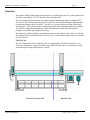
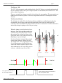
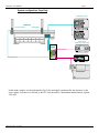
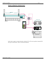
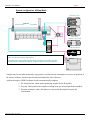
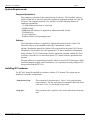
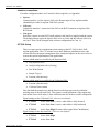
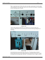
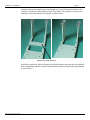
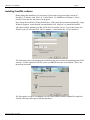
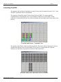
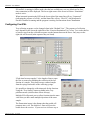
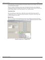
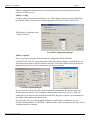
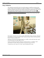
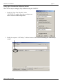
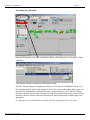
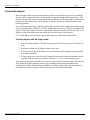
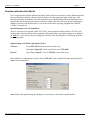
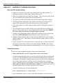
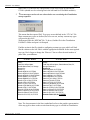
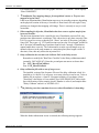
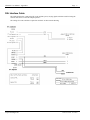
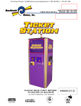
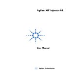
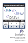
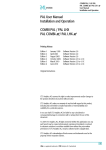
LEAP IFC
User Manual
Document Revision 1.7
LEAP IFC User Manual
Table of Contents
OVERVIEW
1
SYSTEM REQUIREMENTS
7
INSTALLING IFC HARDWARE
7
INSTALLING FRACTPAL SOFTWARE
11
LAUNCHING FRACTPAL
12
CONFIGURING FRACTPAL
13
DELAY CALIBRATION
16
FRACTION REANALYSIS.
19
FRACTION COLLECTION INTO STACKS
20
APPENDIX 1 - INSTALLATION TROUBLESHOOTING NOTES
1
PAL INTERFACE CABLE:
6
LEAP IFC User Manual – Appendix 1
Page 1
Overview
The Agilent-LEAP purification system consists of an Agilent 1200 prep LC system (pumps and
detectors) controlling a CTC IFC fraction collector/Injector PAL.
The IFC sample injection functions are handled within ChemStation using the standard CTC
PAL driver. The fraction collection functions of the IFC are controlled using an additional addon software package called “FractPAL”. FractPAL is a license software package from LEAP
Technologies. This software must be installed separately after ChemStation has been installed.
The software is launched automatically when ChemStation is started after both software
packages are installed and configured correctly.
The FractPAL software handles communications between ChemStation, the Collector PAL and
the Agilent 1200 Automated Fraction Collector (AFC), which sends a signal whenever a fraction
is to be collected.
The IFC PAL
The CTC Integrated Fraction Collector (IFC) is an autosampler and fraction collector. It is a
Twin PAL mounted on a single horizontal beam. Both PALs have their own electronic boards
and control panel along with separate i/o panels.
Fraction Collector PAL
Leap Technologies Inc
Injector PAL
Last Revision date: 10/12/2007
LEAP IFC User Manual
page 2
The Injector PAL
The CTC PAL autosampler on the right hand side of the IFC behaves as an independent unit and
may be controlled either with Cycle Composer (linked to ChemStation) or the internal CTC PAL
driver within ChemStation.
There are no significant changes required to the software for autosampling. The autosampler can
handle both vials and well plates. It can access all positions on the IFC including the collected
fractions.
The Fraction Collector
The left hand side of the IFC is the fraction collector, which has a modified injection head to
accommodate the side-port syringe and collection tubing. It has a special needle guide for
collection. It does not handle raw sample and does not have a wash station. Fraction collection is
initiated by raising the plunger of the side-port syringe
When the plunger is raised above the lower
inlet port, flow is directed downward to the
collection tube. When the plunger is below
this position, flow is direct to waste via the
upper port. There is an O-ring seal at the top
the plunger to prevent leakage.
of
Fraction collection is triggered by a switch
closure signal from the Agilent 1200 AFC.
The Agilent 1200 AFC is operating normally
if it is collecting into a 40x50mL tube tray
with a tube volume matched to the IFC tube.
as
After each run, the AFC tray will be reset in
software, so that the tray is never filled.
Run Start
Run End
UV signal
TTL signal from 1200 AFC to
IFC TTL signal #1 input
Last Revision date: 10/12/2007
Switch closure signal from 1200 AFC to
IFC TTL signal #3 input
LEAP IFC User Manual
page 3
System configuration: Prep Only
Preparative Pumps
LEAP IFC
Fraction Collector
Autosampler
Binary pump
(Make-up in prep mode)
Active
Splitter
Diode Array Detector
Mass Spectrometer
In this mode, samples are injected onto the Prep Valve and signal is monitored by the detectors via the
active splitter. Fractions are collected by the IFC PAL directed by ChemStation method and the Agilent
1200 AFC.
.
Last Revision date: 10/12/2007
LEAP IFC User Manual
page 4
System configuration: Analytical mode
LEAP IFC
Fraction Collector
Autosampler
Anal.
Prep
Binary pump
(Make-up in prep mode)
Active
Splitter
Diode Array Detector
Mass Spectrometer
In this mode, samples are injected onto the Analytical Valve. The active splitter is turned off all
flow goes to the detectors. There is no fraction collection.
Last Revision date: 10/12/2007
LEAP IFC User Manual
page 5
System configuration: A2Prep Mode
Preparative Pumps
LEAP IFC
Fraction Collector
Autosampler
Anal.
Prep
Binary pump
(Make-up in prep mode)
Active
Splitter
Diode Array Detector
In prep mode, active splitter is turned on and all pumps are used, the analytical injector and
column are switched out of the make-up flow.
Mass Spectrometer
In analytical mode, active splitter and prep pumps are turned off. The make-up pump
becomes the main analytical pump with the analytical injector and column switched in.
Samples may be run either analytically or preparative and, because the autosampler can access all positions of
the fraction collector, fractions may be analyzed analytically after collection.
Agilent can supply A2PREP software which can automatically complete:
1. Pre Analytical run, which queues qualifying samples for the Prep phase:
2. Prep run, which purifies the samples according to the pre-selected purification method.
3. Fraction re-analysis, where fractions are re-injected to the analytical system for
confirmation.
Last Revision date: 10/12/2007
LEAP IFC User Manual
page 6
Prep Applications – Higher Flows, up to 100ml/minute
Wider bores are required for all liquid paths. Everything on the PAL in the Prep flowpath is
upgraded to 19gauge
•
Valve inlets, ports and rotor grooves
•
19g inlet sleeves (blue)
•
19g syringes (1ml, 2.5ml and 5ml)
•
Injection head comes with drilled out needle guides
•
Larger bore glass capillaries on wash station.
Fraction Collection adaptations to the collector PAL:
Last Revision date: 10/12/2007
•
“Dilutor” type Side Port syringe assembly acts as a valve
•
Needle never touches raw sample – no wash station
•
Special lower needle guide design
•
Trays are defined with no penetration, needle must clear vials
•
Grounding wire is essential for safety with high flow rates
•
Delay sensor on Waste station wired to Agilent fraction collector
LEAP IFC User Manual
page 7
System Requirements
Computer Workstation
The computer workstation is the central interface for the user. The FractPAL software
will be loaded onto it, and will control the configured component methods via 9-pin RS232 ports. The computer should be a PC and have all of the following features as
minimum requirements:
- 1G MHz Pentium Processor or equivalent
- 64 MB of RAM
-60MB Hard disk Memory for application, additional needed for files
- CD-ROM Drive
-2x 9 pin COM Ports
- Windows 2000 or XP Operating System
Software
The ChemStation software is supplied by Agilent and must be B.01.01 or later. The
FractPAL software is incompatible with earlier ChemStation versions,
Agilent ChemStation controls the Agilent 1200 system and the injection PAL. If below
ChemStation Version B 03.01use the appropriate CTC driver installed in ChemStation
along with the CTC ICC (Instrument Control Components, included with the IFC PAL)
or in later version B 03.01 or later the Agilent CTC Control Software (purchased from
Agilent)
Fraction collection is controlled by FractPAL, which is from LEAP Technologies. While
FractPAL integrates tightly with ChemStation, it is a separately licensed package and is
also provided with the IFC PAL.
Installing IFC hardware
The IFC PAL should be installed in accordance with the CTC Manual. The system may be
installed in 2 possible configurations:
Analytical to Prep:
This system has 2 injection valves; Valve 1 is for prep injections
(large volumes). The fast wash station is mounted to the front of this
valve drive. Valve 2 is for analytical injections.
Prep only:
This system has only 1 injection valve and is dedicated to Prep runs
only.
Last Revision date: 10/12/2007
LEAP IFC User Manual
page 8
Interface connections:
For either configuration there are 2 interface cables required: (see Appendix)
•
Injector:
Connect interface 1 of the Injector PAL to the Remote input of any Agilent module.
(Standard Sync cable for Agilent 1200/PAL system).
•
Collector:
Connect the interface 2 connector of the PAL to the BCD Connector on Agilent 1200
BCD board.
•
Com ports:
Each PAL requires its own RS232 (null modem) cable which is supplied with the system.
The default settings expect the Injector PAL to be on Com1 and the collector PAL to be
on Com2. These can be changed in the software configuration for Com 1-4.
IFC PAL Setup
There are some special considerations when setting up the IFC PAL for the LEAPAgilent applications. The CTC manual covers basic hardware installation issues, this
section describes the proper arrangement of the configured objects on the cross rail so as
to meet the special requirements of the application.
Objects which must be accessible by the Injection PAL:
•
Prep Injection valve
•
Analytical Injection valve (if using)
•
Fast Wash Station
•
Sample Tray(s)
•
Fraction collection trays
Objects which must be accessible by the Collection PAL:
•
Fraction collection trays
•
Collector Waste station
Note that both the sample trays and the fraction collection trays must be within the
working range of the injection PAL. This requires careful placement of the support legs
beneath the cross-rail in order to allow sufficient room for all the accessible components.
Signal settings on the Collection PAL: (these are not default)
•
TTL-In1
Active State Low (is active when slider is fully forward)
•
TTL-In2
Active State Low (is active when slider is fully backward)
•
TTL-In3
Active State High (Fraction collect signal from ChemStation)
Signal settings on the Injection PAL: (these are not default)
Last Revision date: 10/12/2007
•
TTL-In1
Active State High
•
TTL-In2
Active State Low
LEAP IFC User Manual
page 9
There is only about 1cm of slack on the rail to meet these requirements. In order to help
in the positioning of the support legs (which are the first step in the hardware installation)
use the following pictures as guides.
Collector side.
Collector side support leg should line up with the screw to the left of the power
connector. This will leave room on the injector side for the following arrangement of
mountings.
I
n
j
e
c
t
o
r
s
u
p
p
o
r
t
Injector side.
Note that the above picture shows only a Prep valve. The independent wash bottle
bracket should always be mounted between these legs (otherwise the Prep valve cannot
be included in the working range of the PAL). If an analytical valve is added, it must be
Last Revision date: 10/12/2007
LEAP IFC User Manual
page 10
mounted between the support legs of the Sample tray. You will then find that the valve
interferes with the rear most positions on the Tray holder. This problem is resolved by
installing a forward extension to the holder as shown below.
Sample Tray holder extension
Install the extension by first removing the tray holder support legs from the tray platform,
then reassembling with the extension inserted between the tray legs and the tray platform
as shown above.
Last Revision date: 10/12/2007
LEAP IFC User Manual
page 11
Installing FractPAL software
Before doing this installation, it is necessary to first remove any preexisting versions of
FractPAL. To do this, click ‘Start’ Æ ‘Control Panel’ Æ ‘Add/Remove Programs’. Select
FractPAL from the list, and remove the program.
Next, Insert the FractPAL CD into the disk drive. If the setup does not start automatically, using
Windows Explorer, locate the disk icon and double-click ‘setup.exe’ to launch the installer.
After the FractPAL splashscreen, this will be the first window you see. Type in the license key
found in your CD case and Click ‘OK’ to continue. (Note that the key is Case Sensitive).
The following screen is then displayed which allows the user to select the operating mode of the
software. For the Agilent-LEAP IFC system you MUST select the second option. (This is not
the default selection).
The first option is used for a standalone version of the software which is adapted for analytical
fraction collection, and requires different hardware.
Last Revision date: 10/12/2007
LEAP IFC User Manual
page 12
Launching FractPAL
The program will load when ChemStation is started. It may also be launched from the “PAL - Start
FractPAL” pull-down menu in ChemStation.
The program will initially search for the collector PAL on COM2. If it cannot establish
communication it will prompt the user to select another COM port or to run Offline. When
connected, it will download all the Tray objects from that PAL and display them in the main screen
(below).
FractPAL main screen – Trayholder View
The position colored blue is the next collection position. Previously collected fractions are shown
grouped with different colors for each sample. If any trays are excluded from the collection
sequence (see later) they are grayed out as shown in the screen below.
FractPAL main screen when some trays are excluded
Last Revision date: 10/12/2007
LEAP IFC User Manual
page 13
If FractPAL is running in Offline mode, then the last available tray set (or a default set for firsttime connection) will be displayed. The lower right corner of the screen will show “Simulation”
mode is active.
When in normal operation the LED on the lower right of the status line will say “Connected”
(indicating the presence of a PAL), and the Status line will say “Wait CS” which indicated a
FractPAL method is running and the program is waiting for instructions from ChemStation
Configuring FractPAL
Tray collecting sequence can be changed when in the “Method View”. The sequence of collection
trays depends on the list on the right side of the “Fraction Destination Tray” boxes. To re-order this list
or remove trays from the collection sequence use the buttons between the boxes. Only trays on the
right side will be used (in the sequence they are listed).
“Flush time between samples” is the length of time to open
the flow to waste after finishing the collection of the last
fraction of a sample. This cleans out any residual sample
from the syringe and needle of the collecting syringe.
It is possible to change the collection mode for the fractions.
Using the “Tray Setting” button available in the Tray
pulldown menu: (selection here affects all trays).
Multiple Fill will permit you to collect fractions into the same
vials when you have made multiple injections of the same
sample.
The Penetration in mm is the distance that the needle will
penetrate into a vial. The default of –2mm will leave the
needle above the receiver. If your receiver vial has a cap or
Last Revision date: 10/12/2007
LEAP IFC User Manual
page 14
cap mat that needs to be penetrated then the Penetration distance in mm will have to be increased
to a desired penetration depth.
There are a number of Pull-down menus items in FractPAL which allow you to change the
configuration and way the program works. There are TWO basic views in which FractPAL can
operate (Display Modes). Access these from the “Tray” pull-down menu.
TrayHolder View
This is the default view shown above, which shows the user the full bed layout with all
configured trays. There is a status line and status indicator at the bottom of the screen. Only
essential information is provided.
Method View
This view is mainly used for troubleshooting, and provides additional information about the
status of the program. It is also the only place where certain configuration options are available.
FractPAL main screen – Methods View
Last Revision date: 10/12/2007
LEAP IFC User Manual
page 15
Primary configuration functions can be accessed directly from the main pull-down menu in
either view. There are two:
Utilities - Config
Config is where communications settings are set. These should normally not be modified from
their default values (except for selecting the appropriate COM port for the Collector PAL.
This dialogue is displayed when
Config is selected:
FractPAL Configuration dialogue
Utilities - Options
These are advanced settings and should only be configured by LEAP Personnel.
“Quick off” and “Full off” option determine whether the collector plunger is pushed all the way
down between fractions or just far enough to stop flow. The former mode ensures all fraction is
deposited in the tube, but is slows down the move between fractions.
FractPAL Options dialogue
In cases were the collector bed has a forward and backward position, the options under Tray
Holder options need to be set accordingly for both positions and saved. Access by path will
enable the PAL to move the bed with the injection head. By motor, requires a special motorized
tray holder. None indicates the bed is fixed.
Once all of the Trays are defined and the settings are confirmed it is essential to save the
FractPAL default method - FCCHEM.fcc. Otherwise there will be messages that the trays are not
configured properly at startup.
Last Revision date: 10/12/2007
LEAP IFC User Manual
page 16
Delay Calibration
This calibration step should be done by the Agilent engineer at installation and again by the
customer whenever the liquid path to the Collector is modified. It is a way for ChemStation to
determine with high accuracy the time required for flow from the column to the collection point.
This measurement is important to assure accurate and efficient collection of peaks. It is
important that after the delay calibration is done that Chemstation be closed and reopened to
allow all of the settings to be updated for error states. A special Agilent sensor is mounted near
to the Collector waste station on the PAL. This must be defined as a new object in the PAL
firmware.
This should be under the class of objects called “INJECTORS” and have the name “DelaySns”
(case sensitive). It is easy to copy the “Waste” object and rename it then re-teach the position.
Set the Z-Tolerance parameter to 0.
Adjust the XY position and penetration depth very carefully, as the needle must make a good
seal inside the detector at quite high flow rates.
Test the seal with the prep pumps running, by selecting “Move FC to Calib Pos” in the
ChemStation PAL menu. This moves the PAL to this point and opens the flow.
To stop the test, select “Move FC to Park” in the ChemStation PAL menu.
Last Revision date: 10/12/2007
LEAP IFC User Manual
page 17
Setting up the ChemStation Calibration Method
There are two steps to setting up delay calibration using the LEAP IFC.
1. Modify the "Run Time Checklist" in the
“DGCALPS.M” method. Enter the pre and post-run
macros as shown in the dialogue here.
2. Modify the sequence “AFCDelay.s” with the location of the vial/well containing the calibration dye
sample.
Last Revision date: 10/12/2007
LEAP IFC User Manual
page 18
Performing the calibration:
Select the Diagnostics view from ChemStation. When within Diagnostics, select delay Volume
calibration.
ChemStation will then complete the calibration procedure.
The PAL fraction collector (using the pre-run macro, FCP_MoveFCToCalbPort) will move to
the DelaySns position and raise the plunger to allow flow to pass to the sensor and to waste. At
the end of the ChemStation calibration procedure, the post-run macro, FCP_MoveFCToPark,
will lower the PAL fraction collector plunger to send the system flow directly to waste, and will
then move the PAL fraction collector arm back to the park position on the left hand side of the
instrument.
It is important to close ChemStation to update all of the configurations for error states.
Last Revision date: 10/12/2007
LEAP IFC User Manual
page 19
Fraction Reanalysis
If the customer wishes to do fraction reanalysis, then it will probably be necessary to install the
Injector with a syringe which has a 4 inch needle to reach the bottom of the fraction tubes. This
presents some special issues for setup which must be addressed. This long needle is exposed, not
protected by the needle guide, and susceptible to damage. Special care should be taken when
teaching positions.
Access to fraction tubes by the Injector head requires that this PAL be taught the reference point
to the Trayholder called “Slider-G” (or R/F), and that the collector Tray Types be included in the
object set. This PAL cannot reach the normal Slider reference point (it is too far t the left), so an
arbitrary reference point has been selected at the rear right corner of the drip tray.
CTC will include a central reference point on the drip tray itself in future instruments.
Teaching objects with the Long needle.
1. When checking positions, Clear the Z-axis parameter (F2) when not sure if it will be too
deep.
2. Z tolerance settings for all objects must be set to zero.
3. Z Position for all objects should be set to the tip of the needle (imagine the needle guide
at its normal position.)
4. Z Retract must be a value which will ensure the long needle is retracted enough into the
injection head as to not hit any objects. Z Retract = - 16.00 is a good starting point.
After this setup has been established, it is best to create a special firmware backup of the Injector
PAL (using the Loader program) to allow easy switching between long and short needle
configurations. When completed there should be a firmware backup of the fraction collection
PAL and two firmware backups of the injector side (one for each needle length).
Last Revision date: 10/12/2007
LEAP IFC User Manual
page 20
Fraction collection into Stacks
If it is required to do fraction collection into PAL Stacks, then it is necessary to ensure that the injection
does not take place until the collection head is in place over the appropriate plate. Otherwise, if the
injection took place immediately, the time required to open a drawer and position the head may be too
long and the first fraction may be missed. In order to achieve this there are some special configuration
changes which force the Injector PAL to wait at the valve before injecting. (Supported in FractPAL
Version 2.2 and above)
Special Injection cycle in Chemstation
There is a special cycle required called “IFC LCInj” and is supplied on the FractPAL CD. This cycle
contains some extra synchronization commands, and requires some sync signal settings to be changed
on both PALs. (It is not necessary to change the interface cable, the pathways are already provided in
the existing cable).
Signal settings on Collector and Injector PALs.
Collector:
Event TTL-In2 will be used (Active State Low)
Out Signal “Injectd2” will be used and is set to TTL-Out2.
Injector:
Sync Signal “Inject2” is set to TTL-In2 (Active State Low)
In the FractPAL Configuration you must select “TTL-In2” as the Sample start input signal instead of
None (See screen below).
Note: When PAL signal settings are changed, it is necessary to close and re-open FractPAL
Last Revision date: 10/12/2007
LEAP IFC User Manual – Appendix 1
Page 1
Appendix 1 - Installation Troubleshooting Notes
Notes on PAL Hardware Setup
1. Sample Tray extender is very tight when mating to the Tray holder platform. It is
sometimes necessary to file the edge a little to allow it to fit.
2. Delay sensor board needs to be drilled for mounting – This will be done at the LEAP
office if assemblies can be obtained by LEAP ahead of time.
3. Tray types may need to be uploaded to the PAL firmware (using Object manager)
4. The Home position of the Injector PAL needs to be made safe so that if power is
turned off the long needle will not fall onto any objects and be damaged.
5. For the same reason as in 4, the Change syringe position for both PALs needs to be
made safe.
6. The Collection PAL must contain a Wash1 object in the firmware for Cleanup Step
purposes. There will be an error when opening FractPAL that looks PAL ERROR:
Err Code=2, RetCode PALreturn error:[@11:Object not found]
7. If using a Fixed Gilson Rack and the Collection PAL still tries to move the bed then
remove the PATH: Back Rest from the firmware on the Collection PAL.
8. Minimum Default Syringe volume to large for Delay calibration for larger syringes.
Agilent requires 50ul – 100ul range. Lower the minimum syringe volume to 50ul on
the Injector PAL.
9. If the Collection PAL is diverting fractions to waste and waste to fraction tubes then
go into the Collection PAL firmware and confirm that the TTL-In3 Active State is
set to High (Fraction collect signal from ChemStation)(this is not default in firmware)
ChemStation Issues:
*There is now a patch available from Agilent which fixes the noted problems.
1. Delay calibration fails – the AFC reports Delay sensor is not detected.
Consider downgrading the Product type of the Agilent fraction collector from type B
to Type A to void sensing delay sensor. This effectively changes the way the AFC is
recognized by ChemStation, making it behave like an old style G1364A which didn't
have a delay sensor and hence would not look for it during the delay calibration
process. Although this step is not essential, not doing it requires that the AFC delay
sensor must be in place for the calibration to complete. (Or a rigid object such as a
rolled up business card or vial with caps taped to it in its place!)
To make this change, type in at the command line:
print sendmodule$(lafc1, "TYPE G1364A" (case sensitive)
Close ChemStation, power cycle AFC and restart ChemStation. You will need to
Leap Technologies Inc
Last Revision date: 10/12/2007
LEAP IFC User Manual
page 2
remove the G1364B from the configuration screen when it pops up and add the
G1364A (should now be colored green in the left hand list of available modules).
2.
*Error messages such as the one shown below are seen during the ChemStation
startup sequence:
This means that the reported PAL Tray types are not defined in the “CTC.ini” file.
Most common tray types are defined, but a few are not, and any custom tray types
will provoke this error.
Workaround: Edit the “CTC.ini” file. To do so, find the file in the ChemStation
PALDATA folder and open it in Notepad.
Find the section in the file related to configuring custom tray types which will look
like the column on the left. Edit it with the appropriate definition for the unrecognized
tray type. Don’t forget to change the “Plates=n” line to reflect the total number of
plates after your additions:
“Ctc.ini” before
[Plate]
;Add user-defined plate,
Plate#=Name,Row,Col, change
Plates=#+1
Plates=13
Plate0=MT96,8,12,CTCP96
Plate1=MT384,16,24,CTCP384
Plate2=MT384A,16,24,CTCP384
Plate3=DW96,8,12,CTCP96
Plate4=DW96A,8,12,CTCP96
Plate5=VT32-10,8,4,CTCP32
Plate6=VT54,6,9,CTCP54
Plate7=VT78,6,13,CTCP78
Plate8=VT80-Mk2,8,10,CTCP80
Plate9=VT98,7,14,CTCP98
Plate10=VT200,10,20,CTCP200
Plate11=Gilson75,5,15,CTCP75
Plate12=Gilson27,3,9,CTCP27
Plate13=Gil 15-5,5,15,CTCP75
“Ctc.ini” after
[Plate]
;Add user-defined plate, Plate#=Name,Row,Col,
change Plates=#+1
Plates=14
Plate0=MT96,8,12,CTCP96
Plate1=MT384,16,24,CTCP384
Plate2=MT384A,16,24,CTCP384
Plate3=DW96,8,12,CTCP96
Plate4=DW96A,8,12,CTCP96
Plate5=VT32-10,8,4,CTCP32
Plate6=VT54,6,9,CTCP54
Plate7=VT78,6,13,CTCP78
Plate8=VT80-Mk2,8,10,CTCP80
Plate9=VT98,7,14,CTCP98
Plate10=VT200,10,20,CTCP200
Plate11=Gilson75,5,15,CTCP75
Plate12=Gilson27,3,9,CTCP27
Plate13=Gil 15-5,5,15,CTCP75
Plate14=FC50-12,5,10,CTCPERR
Note: The last parameter in the lines (underlined) refers to the graphic representation
of the tray type to show on the screen when the tray type is selected in ChemStation.
Last Revision date: 10/12/2007
LEAP IFC User Manual
page 3
For custom trays, you must select the graphic reference “CTCPERR” which displays
“Plate UNKNOWN”.
3.
*ChemStation Tray mapping changes for unexplained reasons or Trays are not
mapped in logical order.
It has been determined that ChemStation maps trays in ascending sequence depending
on the physical location of the trays. Sort order is from front left to rear right. If tray
positions are changed, then mapping will change. There is currently no way to work
around this.
4. When sampling for injection, ChemStation has been seen to aspirate sample from
incorrect locations.
This has been determined to be caused by the way ChemStation converts PAL tray
positions into alpha-numeric coordinates. This conversion is only done correctly if the
PAL Tray-types are set up so that the PAL “Rows” are in the X direction. (left-right).
Some PAL Tray-types e.g. VT32 and Fraction trays have the “Row-length” defined in
the Y direction with numbering of positions front to back. Currently, ChemStation
cannot handle these correctly. The workaround is to make sure all sample trays are
defined with rows in the same manner as a microtiter plate (Row length is in the X
direction). Note, this only affects the injection PAL.
5. Delay calibration does not move the Collector PAL to the Delay sensor.
Remember to modify the "Run Time Checklist" in the Delay calibration method
(normally “DGCALPS.M”). Enter the pre and post-run macros as shown here:
Pre – FCP_MoveFCtoCalbPort
Post - FCP_MoveFCtoPark
6. Delay calibration fails with an out of range error:.
The installed version of the Sequence File used for delay calibration is bad. It is
installed as a 16-bit file. It is necessary to recreate it before it can be run. To do so
find the file in explorer c:\chem32\1\sequence\afcdelay.s First change it from
"Read Only" then delete it. From within CS go NEW SEQUENCE, add a single
line with location of delay sample (check P number is correct!) and sample name
"Delay Calibrant" and save as AFCDELAY.S
7.
*The following error has sometimes been seen when ChemStation is launching:
When the further information screen is selected, the following message appears:
Last Revision date: 10/12/2007
LEAP IFC User Manual
page 4
This error causes ChemStation to abort, and leaves the CTCSinglID process running,
requiring a reboot of the PC. It has been determined that this is caused by a limitation
imposed in the CTC.ini file for a maximum of 3 Trayholders, and the message is
triggered when a 4th Trayholder as been created on the PAL. The only workaround
currently is to avoid having this many tray holders.
8. If the collection head continues to dispense fractions when stopping a Chemstation
method it is most likely due to a Delay Calibration being performed and Chemstation
closed and re-opened.
Other Possible problems:
1. FractPAL does not see end of run and is still waiting for next fraction signal.
It is possible there is an error message related to another device – Look under
other screens for such error messages (e.g. active splitter).
Workaround – Stop the FractPAL method and restart it again. Worst case, close
and restart FractPAL
2. Message that other COM objects are running, or system hangs at launch.
When ChemStation aborts or crashes, the CTC PAL driver is usually not
unloaded correctly, and will prevent re-launching of ChemStation. Workaround:
In the Task manager, look to see if the CTCSingle ID process is still running, and
if so, stop it. Alternatively, re-boot the system.
FractPAL Installation issues:
1. The “User.mac” file which is located in the “Core” folder under ChemStation is
important in launching FractPAL with ChemStation. This file is used by
ChemStation to launch optional startup macros, and may or may not exist
depending on whether there are any other applications being handled by the
ChemStation application.
This file must be present and contain the following line to launch FractPAL
properly with ChemStation:
Macro "C:\Program Files\LEAPTEC\FractPAL\FractPAL23.mac", go
(Where the Path points to the currently installed version of FractPAL)
A default version of this file is present on the FractPAL installation CD, which
may be copied and used as required. Do not use this file if there is an existing
Last Revision date: 10/12/2007
LEAP IFC User Manual
page 5
version in place. Instead, add the above line to the existing file using notepad.
(Remember that files copied from CD’s have “read only” attributes and this must
be unchecked in the file properties after it is copied).
Note: If there is no User.mac file, it is possible to check if FractPAL will launch
correctly from within ChemStation, by typing in the above line directly into the
command-line of ChemStation.
2. If upgrading FractPAL at an existing site, first go through the Windows Control
Panel to uninstall any previous versions. (You may wish to backup or rename the
original FractPAL folder before doing so).
Do not simply copy individual files, unless specifically told to do so by LEAP.
There are several files which must work together and doing so incorrectly may
result in file incompatibilities.
Last Revision date: 10/12/2007
LEAP IFC User Manual – Appendix 1
Page 6
PAL Interface Cable:
The cable shown below connects the IFC to the Agilent system, carrying signals which are used for timing the
fraction collection as well as the sample injection.
The settings for events which are required on each PAL are shown on the drawing.
Leap Technologies Inc
Last Revision date: 10/12/2007