1
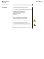
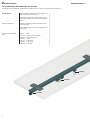
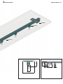
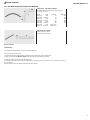
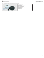
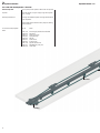
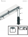
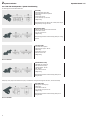
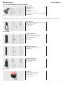
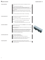
Technic
E
Operation Manual
ASS Track System
1
1-4 Contents
1
2
Operation Manual / ASS
Contents
Introduction
System Installation
Seite
1.1 General Instructions
3
1.2 Approved Use of System
3
1.3 Unapproved Use of System
3
1.4 Technical Data
3
1.5 Further Information
3
2.1 Installation
4
2.2 Preparation
5
2.2.1 Delivery of System
5
2.2.2 System Design
3
System Operation
2.3 Track Mounting
6 - 16
2.3.1 System Parts Mounting
• Walk-Along Track
• Side Cord Operation
6 - 11
12 -15
2.3.2 Rope Attachment
16
2.3.3 Rope Operation Test
16
2.3.4 Curtain Attachment
16
2.3.5 Curtain Operation Test
16
2.3.6 Operation
16
3.1 Operator Instructions
17
3.2 Instruction of Untrained People in Working Area
4
2
Safety Instructions
3.3 Maintenance
17
3.4 System Modification
17
4.1 Safety Risks
18
Information
All information subject to technical modifications without notice.
Updated 07/2010.
1 Introduction
1.1 General Instructions
Operation Manual / ASS
ASS is a track system for lightweight curtains up to 4 m high.
For permanent installations only.
Walk-along track (no cable-pull operation).
Side cord operation: for straight track configurations up to 12 m long only.
ASS is not suitable for motor operation.
Operation Manual
This operation manual is included in the delivery of the ASS track system. It includes
all necessary instructions to assemble and to operate the system safely and to prevent
accidents or damage.
1.2 Approved Use of System
ASS is approved for moving textile curtains up to 4 m high within the maximum load
capacity of the track and associated components.
Do not exceed load rating of track and runners.
1.3 Unapproved Use of System
Do not attach solid objects, such as scenery or decorative objects to the track. If the
system is overloaded, objects can fall and risk hurting individuals or damaging material.
1.4 Technical Data
Track weight:
340 g/m
Track section lenght
6,00 m
Max. distance between hanging points: 1m
Minimal curve radius:
250 mm
Load Capacity
(Table + Diagram)
ASS track sections are available in two versions:
•Predrilled: predrilled holes (20 cm increments) in top of the track allow for bolting directly into the ceiling.
•Solid track sections: track is mounted to ceiling/structure with ceiling mounting
plates (article number 3100 8021/8022) .
Maximum Load Capacity in Correlation to Track Span Width:
Span width: Point load: Uniform distributed load
1,00 m
12 kg/m
25 kg/m
Attention!
If using ceiling mounting plates, the ceiling mounting plate will be considered the Point
Load point.
Verify that the ceiling/structure and all attachment accessories are stable and in a
proper condition.
1.5 Further Information
You can find further information , such as load capacity, dimensions and weight of all
track system components in chapter 2.3 „Track Mounting“, in the Gerriets TECHNIC
manual and on our website www.gerriets.com.
3
2 System Installation
2.1 Installation
Operation Manual / ASS
Installation of the ASS system must be done by qualified technicians only. All installers
must follow the operation instructions.
Not following the operation instructions can damage the system. Gerriets GmbH is not
liable for these damages.
4
2 System Installation
Operation Manual / ASS
2.2 Preparation
2.2.1 Delivery of System
Please check immediately that the delivery slip matches the received parts and compare to images in chapter „2.3 Track Mounting“ to verify that the shipment is complete.
2.2.2 System Design
For designing your custom track system, please note following points.
For the track system length you must include the curtain stacking space (length of each
runner and master runner) and length of the required components such as end stops,
return pulley and head pulley at the ends of the tracks.
Stacking space calculation for each side of the curtain:
Number of runners (5 – 7 each m) x length of each runner
+ lenght of master runners
+ head of head and return pulleys
+ length of end stop
Calculate the curtain weight.
Define the track mounting style and the number of hanging points.
The maximum load as defined in table 1.4 must not be exceeded.
Note:
Please only use the system for its approved use of moving curtains up to 4 m high.
Ensure that the ceiling/structure the track is mouted to is stable.
Secure the working area during installation as there is the risk of falling objects.
Make sure that you/your employees follow fall protection regulations during the installation.
Follow the mounting instructions for each track system component in the following
chapter.
5
2 System Installation
Operation Manual / ASS
2.3 Track Mounting / ASS: Walk-Along Track / Overview
The following pages include drawings and descriptions of the ASS track system as well as mounting instructions and useful tips.
Walk-Along Track
Walk-along tracks are systems without motor operation. The
curtains are opend and closed manually.
Walk-along is the basic system to open or close curtains or
to move scenery along a track (unapproved use for ASS track
system).
Mounting Considerations
For design and installation consider overall height of track
system components.
Please calculate length of each runner and master runner for
stacking space.
List of Parts for Sample System
Below
Art.-No.
Article
3105 1011 3100 8021 3105 0031 3105 0011
3105 0021
3105 9012
track, straight, black anodized
ceiling mounting plate
end stop
master runner
2-wheel runner
curtain hook
3105 9012
3105 0011
3105 0031
6
2 System Installation
Operation Manual / ASS
3100 8021
3105 0021
3105 1011
Ceiling/Structure
69
50
4
Ceiling/Structure
20
72
17
25
100
End View
Side View
7
2 System Installation
Operation Manual / ASS
2.3.1 ASS: Walk-Along Track / System Parts Mounting
Track, Straight
•Extruded aluminum profile ALMgSi 0,5 F22.
•Steel pin connection.
Art.-No.
Colour
3105 1011
black
3105 1012 aluminum
3105 1021 black
3105 1022 aluminum
Length cm
600
600
up to 600
up to 600
Weight g/m
340
340
340
340
Track, Straight, Predrilled
•Technical details: see track straight.
•Predrilled holes in top of track in 20 cm increments.
Art.-No.
3105 1013
3105 1014
3105 1023
3105 1024
Colour
black
aluminum
black
aluminum
Length cm
600
600
up to 600
up to 600
Weight g/m
340
340
340
340
Track, Curved - without Splice
•Technical details: see track straight.
•1/4 circle, 90° curve.
Art.-No.
3105 1031
3105 1032
3105 1051
3105 1052
3105 1071
3105 1072
3105 1091
3105 1092
Colour
black
aluminum
black
aluminum
black
aluminum
black
aluminum
Radius cm
25
25
50
50
100
100
custom curve
custom curve
Weight g/m
134
134
267
267
534
534
-
Track, Curved - without Splice, Predrilled
• Predrilled holes in top of track in 20 cm increments..
•1/4 circle, 90° curve.
Art.-No.
3105 1033
3105 1034
3105 1053
3105 1054
3105 1073
3105 1074
3105 1093
3105 1094
Colour
black
aluminum
black
aluminum
black
aluminum
black
aluminum
Radius cm
25
25
50
50
100
100
custom curve
custom curve
Weight g/m
134
134
267
267
534
534
-
Track, Curved - with Splice
•Technical details: see track straight..
•1/4 circle, 90° curve.
Art.-No.
3105 1041
3105 1042
3105 1061
3105 1062
3105 1081
3105 1082
3105 1101
3105 1102
8
Colour
black
aluminum
black
aluminum
black
aluminum
black
aluminum
Radius cm
25
25
50
50
100
100
custom curve
custom curve
Weight g/m
270
270
403
403
670
670
-
2 System Installation
Operation Manual / ASS
2.3.1 ASS: Walk-Along Track / System Parts Mounting
Track, Curved - with Splice, Predrilled
• Predrilled holes in top of the track in 20 cm increments.
•1/4 circle, 90° curve.
Art.-No.
3105 1043
3105 1044
3105 1063
3105 1064
3105 1083
3105 1084
3105 1103
3105 1104
Colour
black
Aluminum
black
Aluminum
black
Aluminum
black
Aluminum
Radius cm
25
25
50
50
100
100
custom curve
custom curve
Weight g/m
270
270
403
403
670
670
-
Joint Pin, Set of 10 pieces
•Steel pin Ø 2 mm x 40 mm.
• For precise track connection..
Art.- Nr. 3105 9115
Track Mounting
Track sections can be bolted directly to ceiling or to wood substructure.
There are two track mountig options.
1. Predrilled track sections: Predrilled holes for bolting the track section directly to the ceiling/structure.
2. Ceiling mounting plate (3100 8021 / 8022). Please follow the following mounting instructions.
For seamless, precise track section connection please note:
If you shorten a track section, the cut must be straight and at a right angle. Deburr the cut edge to ensure a precise joint connection of
the track sections.
Joint pins help to connect track sections seamlessly and keep in aligned.
9
2 System Installation
Operation Manual / ASS
2.3.1 ASS: Walk-Along Track / System Parts Mounting
2-Wheel Runner
For straight and curved sections.
In combination with curtain hook tape (4104 0151 / 0152) and
curtain hooks (3105 9012): runner distance approx. 15 – 20
cm.
•Load capacity: 2 kg.
•Weight: 10 g.
Art.- Nr. 3105 9115
Carrier
With 4 load bearing wheels..
Eyelet for curtain attachment.
With rope attachment bracket.
•Load capacity: 4 kg.
•Weight: 160 g.
Works as the first curtain carrier (rope attachment bracket not
used for walk-along systems).
Art.- Nr. 3105 0011
Ceiling Mounting Plate
For direct ceiling/structure mounting.
With hole to accept M6 bolt (bolts and anchors not included).
•Load capacity: 1.000 N.
•Weight: 185 g.
Art.- Nr. 3100 8021 black / 3100 8022 Aluminum
1 Distance: maximum 1 m , depending on curtain weight. Use
diagram in chapter 1.4 to definde the d istance between
ceiling mounting plates!
2Verify that ceiling/structure and all attachment accessories
(bolts, anchors) are stable and in a proper condition.
Recommendation:
Helde HKD-M6 x 30 screw M6 x 25 DIN 779.
3Bolt ceiling mounting plate to ceiling/wood substructure.
4Squeeze both plates to the track and tighten M4 nuts.
End Stop
•With screw
•Weight: 10 g.
Art.- Nr. 3105 0031
Curtain Hook
•V4A steel.
•Corrosion-resistant even with impregnated textile curtains.
•Weight: 5 g.
Both ends of the hook are slid into the pockets of the curtain
hook tape (see page 11).
Art.- Nr. 3105 0031
10
2 System Installation
Operation Manual / ASS
2.3.1 ASS: Walk-Along Track / System Parts Mounting
Curtain Hook Tape
•With holes for curtain hooks.
•With 2 pull lines.
•For up to 100% fullness.
•Sold in complete roles only..
•Role length: 50 m.
•Height: 50 mm.
Art.- Nr. 4104 0151 white / 4104 0152 black
11
2 System Installation
Operation Manual / ASS
2.3.1 ASS: Side Cord Operation / Overview
Side Cord Operation
The only cord operation system for ASS is side cord operation.
Important
Side cord operation is only for straight, single track systems
up to 12 m long.
Mounting Considerations
For design and installation please note height measurements
of all components.
Please include length of head and return pulleys for stacking
space calculation.
List of Parts for Sample System
Below
Art.-No.
Article
3105 1013 3105 0041 3100 0121 3105 0051
3105 0031
3105 0011
3105 0021
4104 1162
3100 7071
3105 9012
track, straight, predrilled, black anodized
head pulley
single return pulley
rope guide pulley
end stop
master runner
2-wheel runner
polyester rope Ø 6 mm
adjustable floor pulley 180
curtain hook
3105 0021
3100 0121
12
2 System Installation
Operation Manual / ASS
3105 0041
3105 0051
3105 0031
4104 1162
3105 1013
3105 0011
3105 9012
3100 7071
Ceiling/Structure
65
51
Ceiling/Structure
160
20
72
17
100
End View
Side View
13
2 System Installation
Operation Manual / ASS
2.3.1 ASS: Side Cord Operation / System Parts Mounting
The following parts are available for ASS track.
Head Pulley
•Diverts operation rope to floor.
•For single and double track systems.
•Ball bearing..
• Groove base: 25 mm.
•Fo use with rope up to Ø 8 mm.
•Weight: 445 g.
Art.- Nr. 3105 0041
With mounting plate 100 x 60 mm with 4 holes (Ø 6,5 mm) for
bolting directly to ceiling /structure.
Single Return Pulley
•Returns operating rope at the end of the track.
•Groove base: 70 mm.
•For rope up to Ø 8 mm.
•Weight: 530 g.
With mounting plate with 4 holes for bolting directly to ceiling/
structure.
Art.- Nr. 3100 0121
Cross-Over Pulley
•For double track systems.
•Rope diversion: approx. 160 mm.
•Ball bearing.
•Groove base: Ø 70 mm.
•Bis max. Ø 8 mm Seil.
•Weight: 935 g.
Art.- Nr. 3100 0131
Tensioned Return Pulley
•Adjustable rope tensioning.
•Can replace return pulley.
•Tension distance: 150 mm.
•Ball bearing.
•Groove base: Ø 70 mm.
•Weight: 975 g.
Art.- Nr. 3100 0111
With mounting plate with 4 holes for bolting directly to the
ceiling/structure.
Head pulley, return pulley and tensioned return pulley are bolted to the ceiling/sructure aligned to the track. (see overview above)
Rope Guide Pulley
•No sag of the returning rope.
•Ball bearing..
•Groove base: Ø: 25 mm.
•For use with rope up to Ø 8 mm.
•Weight: 190 g.
With mounting plate with 2 holes for bolting directly to the
ceiling/structure.
Art.- Nr. 3105 0051
14
2 System Installation
Operation Manual / ASS
2.3.1 ASS: Side Cord Operation / System Parts Mounting
Rope Guide Pulley
•Guides returning rope.
•Ball bearing.
•Groove base: Ø 25 mm.
•Weight: 165 g.
•For use with rope up to Ø 8 mm.
With mounting plate with 2 holes (Ø 6.5 mm) for bolting directly
to ceiling/structure.
Art.- Nr. 3100 0141
Rope guide pulleys are mounted to the ceiling/structure next to the track to align the returning rope parallel to the track. A rope guide pulley can also align the rope along the wall.
Stirrup Floor Pulley
•With foot stirrup and two 10 mm holes for bolting to the floor.
•Rope tensioning by foot pressure.
•For rope up to Ø 8 mm.
•Weight: 1.205 g.
Art.- Nr. 3100 7061
Adjustable Floor Pulley 180
•Cord tensioning by height adjustment.
•With four Ø 10 mm holes for bolting to floor.
•For use with rope up to Ø 8 mm.
•Tension distance: 180 mm.
•Weight: 1395 g.
Art.- Nr. 3100 7071
Adjustable Floor Pulley 350
Wie 3110 7071, but tension distance: 350 mm.
•Weight: 3.600 g.
Art.- Nr. 3110 7081
Self Tensioning Floor Pulley
•Mit 4 holes for bolting to floor.
•For use with rope up to Ø 8 mm.
•Weight: 12.445 g.
Art.- Nr. 3110 7011
Polyester Rope
•Ø 6 mm.
•Colour: black (also available in white).
•Tensile strenght approx. 575 daN.
•Max. length: 200 m.
•Non-stretch (ca. 4 %).
Art.- Nr. 4104 1162
15
2 System Installation
2.3.2 Rope Attachment
Operation Manual / ASS
After assembling all parts, the side cord operation cord (standard Ø 6 mm) can be
attached.
1Attach one end of the rope to a master runner.
2Guide the other end of the rope over the head pulley to the floor pulley back up to the
head pulley, to the return pulley and back to starting point (master runner).
Loosen the rope at the starting point (master runner), pull the rope tight and clamp it
to the master runner.
3After the installation, cut off the remaining ends of the rope to ensure a smooth
operation.
4 Check the rope tension latest four weeks after installation. If necessary, adjust the
tension.
The different cord guide systems are shown in chapter 2.3 “Track Mounting”
2.3.3 Rope Operation Test
Before attaching the curtain, the track system operation must be checked.
Please pay attention to the following:
Does the rope run smoothly, or does it rub against system components or other
objects?
If yes: change the rope alignment or add additional rope guides.
Do you notice any unusual or loud operation noise?
If yes: Find out the cause and replace defective parts where required.
2.3.4 Curtain Attachment
You can attach a curtain via curtain hook tape (3105 9012) and curtain hooks (4104
0151/2). You can also use tie line.
Do not exceed the maximum load capacity of the track system (see chapter 1.4) and its
components (chapter 2.3.1)!
Attach the movable part of the curtain to the master runner’s lead eyelet and to the
other runner‘s attachement holes. To prevent the curtain from overtraveling the end
position, attach the other end of the curtain between two end stops (see image)
The distance between the bottom edge of the curtain and the floor should be 1-3 cm to
prevent the curtain from brushing over the floor.
2.3.5 Curtain Operation Test
Double-check after curtain attachment
• Does the curtain move smoothly and easily?
• Is there a danger of collision with other objects in the curtain area?
If yes:
Enlarge the safety distance between curtain and other objects or remove the
obstacles. Repeat the test after removing the cause of the collisi on.
2.3.6 System Operation
Before operating the system ensure that all safety regulations are followed.
System operators must be instructed about the system .The operator must have a clear
view of the entire curtain area.
16
3 System Operation
Operation Manual / ASS
3.1 Operator Instructions
To operate the system safely, operators must have a basic knowledge of design and
function of the system. It is the owner’s responsibility to instruct operators accordingly .
3.2 Instruction of Untrained People in
the Working Area
Untrained people who work in the system area must be informed about possible safety
risks and proper procedures.
3.3 Maintenance
During operation be aware of unknown or unusual noises. This will help prevent major
damage in the future.
The following should be checked as indicated:
each use
Unusual noise
bi-annually
annually
X
Rope: condition
Rope: Tension
X
X
Master runner+runner: smooth operation
X
Master runner+ runner: silent operation
X
Master runner + runner: sight check of
wheels
deformation of casing or attachment
accessories.
X
Runner curtain atttachment
X
Master runner: rope attachment
X
Rope guides: smooth operation
X
Suspension points: sight check and screw
connections
X
Track connections
X
Staining
X
For heavy duty applications shorter maintenance cycles are recommended. Damaged
and defective parts must be replaced.
For product details please see our Technic Manual, go to www.gerriets.com or contact
our customer support team.
3.4 System Modifications
System modification is not allowed without the written consent of Gerriets GmbH.
Only genuine Gerriets spare parts should be used.
Unapproved modifications will result in voided warranty and liability.
Manual copyright:
Fa. Gerriets GmbH
Im Kirchenhürstle 5-7
D 79224 Umkirch
17
4 Safety Instructions
4.1 Safety Risks
18
Operation Manual / ASS
Even with approved operation and regular maintenance, safety risks can not be totally
excluded. Please note following risks:
Risk
Cause
Action
Break during Operation
Overload, wearing
Do not exceed load capacity, regular maintenance
Objects falling down
Unsecured screw connections are loose, collision
with other structures
Proper screw connections
and regular checks; keep
safety distance
Operation Manual / ASS
Business hours
Monday - Thursday
8:00 a.m.- 12:00 p.m.
1:00 p.m.- 5:00 p.m.
Friday
8:00 a.m.- 12:00 p.m.
1:00 p.m.- 3:30 p.m.
Commercial register,
Freiburg
Tax number
HRB-Nr. 2678
142191543
You can reach our telephone switchboard on weekdays from
Managing Directors
Walter Gerriets
Hannes Gerriets
Bernd Baumeister
DTHG and ITI member
8:00 a.m.- 6:00 p.m.
Outside normal business hours, please leave a message and we
will get back to you the next business day.
Shipping address
GERRIETS GmbH
Bühnenbedarf
Im Kirchenhürstle 5 - 7
D-79224 Umkirch
Mail address
GERRIETS GmbH
Bühnenbedarf
Postfach 1154
D-79220 Umkirch
Telephone switchboard
+49 7665 - 960 0
Team 5 Sales
• Theatres and stage design
+49 7665 - 960 250
Team 4 Sales
• Stage equipment for town halls
• Multi purpose halls
• Schools
• Universities
• Churches
+49 7665 - 960 240
Team 3 Sales
• Event technic
• Event furnishing
• Amusement parks
• Movie theatres and TV studios
+49 7665 - 960 230
Team 2 Sales
• Trade show equipment and
exhibition stand construction
• Industry clientele
• Ship furnishing
+49 7665 - 960 220
Team 1 Sales
• Stage design companies
• Planners and architects
+49 7665 - 960 210
Shipping Department
Accounting Department
+49 7665 - 960 126
+49 7665 - 960 170
Fax numbers
General Inquiry
+49 7665 - 960 125
Online
Internet
E-mail
www.gerriets.com
[email protected]
Address
Phone numbers
19
07 / 2010
Gerriets GmbH
Im Kirchenhürstle 5-7
DE-79224 Umkirch
+49 7665 960-0
+49 7665 960-125
[email protected]
Gerriets S. A. R. L.
Rue du Pourquoi Pas
FR-68600 Volgelsheim
+33 3 89 22 70 22
+33 3 89 22 70 50
[email protected]
Gerriets International Inc.
130 Winterwood Avenue
US-Ewing NJ 08638
+1 609 758-9121
+1 609 758-9596
[email protected]
Gerriets Great Britain Ltd.
18 Verney Road
GB-London SE16 3DH
+44 20 7639 7704
+44 20 7732 5760
[email protected]
Gerriets Handel GmbH
Gorskistraße 8
AT-1230 Wien
+43 1 6000 600-0
+43 1 6032 585
[email protected]
Gerriets España S. L.
Pol. Ind. Arroyo Buzanca
Avda. de Las Moreras
Sector S-19 B, Naves 1-2-3
ES-28350 Ciempozuelos, Madrid
+34 91 134 5022
+34 91 134 5084
[email protected]
www.gerriets.com
20
Gerriets Italia
Risam for show
Viale Spagna 150 / B
IT-20093 Cologno Monzese (MI)
+39 02 2532 113
+39 02 2532 130
[email protected]
Gerriets Korea
4F 449-4 Seongnae-dong
Gangdong-gu, Seoul
KR-Korea 134-030
+82 2 477 7713
+82 2 477 1490
[email protected]
Gerriets Belgique
Distribué par :
Gerriets S. A. R. L.
Rue du Pourquoi Pas
FR-68600 Volgelsheim
+33 3 89 22 70 22
+33 3 89 22 70 50
[email protected]
Gerriets Slovenia
MAORI d.o.o.
Miklosiceva 15a
SI-1000 Ljubljana
+386 143 052 79
+386 143 052 79
[email protected]
Gerriets Nederland
LevTec BV
Anthony Fokkerweg 3
NL-1059 CM Amsterdam
+31 20-40 82 553
+31 20-40 82 662
[email protected]
Gerriets Hellas
Stage Art EPE
Stournari 27B
GR-10682 Athens
+30 210 3836 715
+30 210 3811 929
[email protected]
Gerriets Turkey
Benart Ses Isik-ASC Is Merkezi
Mahmut Sevket Pasa Mahallesi
Piyale Pasa Bulvari
Baran Sk No: 4 Kat: 3 Zemin Kat
TR-34384 Okmeydani-Sisli-Istanbul
+90 212 254 33 43
+90 212 254 33 53
[email protected]
Gerriets South Africa
AVL Productions
P.O.Box 70740
4, Ealing Crescent
ZA-2021 Bryanston
+27 11 463 5804
+27 11 463 5809
[email protected]