1
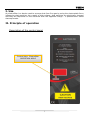
Tech User manual ST-360 1 User manual ST-360 2 Tech I. Use An electrofilter is a device used to remove dust from flue gas by using the electrostatic force influencing dust particles. As a result of high voltage, dust particles are electrically charged and they are deposited on the electrode with the opposite charge – a phenomenon called electrophoresis. II. Principle of operation Description of the control panel Control light: Electrofilter OPERATION MODE 3 User manual ST-360 The controller offers the following modes of operation: 1. Uninitialized. 2. Stand-by mode. 3. Operation mode. 4. Emergency operation 5 Alarm Uninitialized – after ST-360 controller is switched on, this mode is activated - the controller checks current flue gas temperature and the presence of 50 Hz frequency. If the flue gas sensor is not detected, or it is damaged or if there is no 50Hz frequency, the controller enters alarm mode. Otherwise the stand-by mode is activated. Stand-by mode – In this mode the controller monitors the temperature increase in the chimney. If the temperature increases by a pre-defined number of degrees within a specified period of time (the measurement starts from the fan activation threshold or after the fan activation temperature has been reached), the controller detects the firing-up process in the CH boiler. In order to protect the electrodes against dust deposition, the fan is switched on. If the temperature drops below the fan activation threshold, the fan is switched off. If the flue gas temperature reaches the pre-set operation value, the electrofilter enters operation mode. Operation – in this mode high voltage is activated. If the device fails to detect adequate increase in voltage (up to gear 5), the controller signals the shorting of electrodes error (E3). Otherwise the device enters operation mode. The voltage increases at specified times until the pre-set value is reached. In the event of overvoltage the device switches to Uninitialized mode and the activation procedure is started anew. The incidence of overvoltage is saved in the device memory for a specified period of time. If the number of such events exceeds the pre-set acceptable number, the device switches to emergency mode. Emergency mode – in this mode the voltage does not exceed the value at which overvoltage occurred. If the voltage generated in this mode is not sufficient for the device to operate properly, the alarm mode is activated. III. Controller parameters in different modes: Uninitialized This mode is active right after the device is switched on and after the overvoltage has been detected. The device controls the parameters and performs the first measurements. Fan – OFF High voltage- OFF Display shows „0” Stand-by This mode follows after „Uninitialized mode” if no errors occur. If may be followed by operation mode provided that the operation parameters have been reached. Fan – activated after temperature increase is detected, or after the activation temperature has been reached. High voltage - OFF Display shows current flue gas temperature. Operation This mode follows after stand-by mode when a pre-defined flue gas temperature has been reached. When the flue gas temperature drops below this value by the hysteresis 4 Tech value, the device enters stand-by mode. The device operates in two modes. 1. Normal operation – full operation range of MOSFET is used. The device aims to reach 20kV. 2. Emergency operation – if a certain number of overvoltages occur within a predefined period of time, the device switches to emergency operation mode. MOSFET operation range is limited to the last acceptable voltage value. If this value is not sufficient to reach the minimum of 18kV, the device reports an alarm and switches off. Fan - ON High voltage - ON Display shows one of the following letters: P – normal operation A – emergency operation as well as the current fan gear. Alarm After an alarm situation is detected, the device switches to alarm mode. In order to return from this mode, the user must reset the device. Fan - ON High voltage - OFF Display shows flashing „E” and error number. IV. Protections In ST-360 alarms are shown on a three-segment display (flashing “E” + error number). If the device detects more than one error, the information on the display will change every three seconds. In order to return from the alarm mode, ST-360 must be disconnected from the power supply. In alarm mode, high voltage is always switched off (generator and MOSFET control). The device activates the fan which blows air into the electrofilter chamber. Alarm numbers: 1. Flue gas sensor damaged – flue gas sensor is disconnected or damaged. 2. No 50Hz measurement - no 50Hz frequency, essential for MOSFET control. This error may also occur when the acceptable operating range is exceeded. 3. MOSFET activation impossible – the device detects shorting of the electrodes. Measurement is performed from gear 5. In some cases of electrodes shorting error 4 may appear. 4. Operation above the pre-set threshold – despite reaching the highest possible gear, the pre-set value has not been reached. 5. Operation below the pre-set threshold – the pre-set value has been reached below the threshold of 18kV. In case of errors 3-5, it is necessary to perform maintenance and clean the electrodes. CAUTION: Make sure that the electrodes have been earthed. 5 User manual ST-360 V. Operation parameters Fan: Minimum flue gas temperature: 15°C Time of flue gas temperature measurement - 5 minutes Delta of flue gas temperature increase- 5°C Fan activation temperature - 35°C High voltage Temperature of high voltage activation- 50°C Hysteresis - 2°C Generator frequency - 18kHz Duty cycle - 50% MOSFET activation/deactivation delay before/after generator 0,5s Short-circuit impulses - 100 Pre-set impulses - 1000 Minimum impulses - 860 Inertia - 12 Voltage spike impulses - 30 Max. number of overvoltages to activate emergency operation mode -10 Overvoltage deletion delay - 5 minutes Number of MOSFET operation ‘gears’ - 100 Minimum operation gear - 10 Maximum operation gear - 90 Start from gear 3 6 Tech 7 User manual ST-360 8