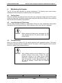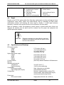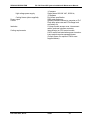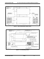
1
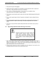
XENON CORPORATION
RC-742 Pulsed UV System Installation & Maintenance Manual
RC-742
Pulsed UV System
Installation & Maintenance Manual
Bringing new technology to light!
37 Upton Drive
Wilmington, MA 01887 USA
(978) 661-9033
Part # 810-0057; Rev E
fax: (978) 661-9055
e-mail: [email protected]
www.xenoncorp.com
3/9/06
i
XENON CORPORATION
RC-742 Pulsed UV System User Manual
RC-742
Pulsed UV System
Installation & Maintenance Manual
Return and Warranty Information
Company Name_____________________________________________________________
Equipment Description________________________________________________________
Equipment Location_____________________________
Equipment #__________________
PFN Serial #__________________________________
HVPS Serial #_________________
Housing Serial #________________________________
Date Installed_________________
Lamp 1 Serial #________________________________
Date Installed_________________
Lamp 1 Part #_________________________________
Length of Service______________
Lamp 2 Serial #________________________________
Date Installed_________________
Lamp 2 Part #_________________________________
Length of Service______________
Lamp 3 Serial #________________________________
Date Installed_________________
Lamp 3 Part #_________________________________
Length of Service______________
Lamp 4 Serial #________________________________
Date Installed_________________
Lamp 4 Part #_________________________________
Length of Service______________
Bringing new technology to light!
37 Upton Drive
Wilmington, MA 01887 USA
(978) 661-9033
fax: (978) 661-9055
e-mail: [email protected]
www.xenoncorp.com
Part # 810-0057; Rev E
11/28/06
ii
XENON CORPORATION
RC-742 Pulsed UV System User Manual
1. General Information
1-2
1.1 About This Installation & Maintenance Manual
1.2 Symbols Used
1.3 Warranty
1.3.1 Statement
1.3.2 Return Return Procedure
1.4 Getting Help
1.4.1 Xenon Web Site
1.4.2 Correspondence
1.4.3 Telephone Numbers
1-2
1-2
1-2
1-2
1-3
1-3
1-3
1-4
1-Error! Bookmark not defined.
2. Product Safety Information
2-2
2.1 Rupture Precautions
2.1.1 Preventing Rupture
2.1.3 Handling Breakage
2.2 High Voltage and Electrostatic Discharge Precautions
2.3 UV/VIS Light Precautions and Filtering
2.4 Ozone Precautions and Venting
2.5 Mounting and Interconnection Stability Precautions
3. Installation and Operation
3-1
3.1 Introduction
3.2 System Components
3.2.1 PFN Control Module
3.2.2 High Voltage Power Supply
3.2.3 Lamp Module
3.3 Options
3.4 Tools and Equipment
3.5 Environmental Specifications
3.5.1 Cooling Requirements
3.5.2 Utility Requirements
3.5.3 Control Interface
3.6 Unpacking and Initial Inspection
3.6.1 Components Included
3.6.2 Unpacking the System
3.7 System Installation
3.8 System Operation
3.8.1 Continuous and Cycled Modes
3.8.2 Power-up and Cure
3.8.3 Faults and System Power-down
3-1
3-1
3-1
3-2
3-2
3-3
3-4
3-4
3-4
3-4
3-6
3-12
3-12
3-12
3-12
3-13
3-14
3-14
3-14
4. Maintaining the System
4.1
4.2
4.3
4.4
4.5
2-2
2-2
2-1
2-2
2-4
2-5
2-6
4-1
Cooling Vents
Lamp Housing and Flash Lamp
Troubleshooting
Repair
Specifications and Drawings
4-1
4-1
4-1
4-1
4-3
5. Field Bulletins
5-1
5.1 Rapid ON-OFF cycling of the high voltage (Bulletin No. 989-0022)
Part # 810-0057; Rev E
11/28/06
iii
5-1
XENON CORPORATION
RC-742 Pulsed UV System Installation & Maintenance Manual
1.
General Information
1.1
About This Installation & Maintenance Manual
In addition to general company, product and safety information, this manual provides an
overview of the RC-742 product and specifications with instructions for application, installation,
maintenance and replacement. See the appropriate lamp housing Installation & Maintenance
manual for details on lamps and housings. Fill in the product identification page in this manual
so that your equipment module serial numbers and pertinent data are recorded in case of
problems or warranty claims.
1.2
Symbols Used
Xenon is committed to its customers and the safe use of its products. Since high voltage,
electrostatic discharge, ozone, and UV light can cause hazardous conditions, the following
types of warning symbols are included in this manual.
WARNING
A WARNING message means that failure to follow
directions could result in bodily harm or loss of life.
CAUTION
A CAUTION message means that failure to follow
directions could result in damage to equipment or
loss of operation.
NOTE
A NOTE gives important clarifying information or
specific instructions.
Part # 810-0057; Rev E
3/9/06
1-1
XENON CORPORATION
1.3
RC-742 Pulsed UV System Installation & Maintenance Manual
Warranty
1.3.1 Warranty Statement
XENON Corporation
Warranty
Seller warrants to the first purchaser (i) each System sold by it to be free from defects in materials and workmanship
for a period of one (1) year from date of shipment from the factory; (ii) all Components sold by it to be free of
defects in material and workmanship for a period of ninety (90) days from the date of shipment from the factory;
and (iii) all Lamps sold by it to be free of defects in material and workmanship for a period of thirty (30) days from
the date of shipment from the factory. Seller’s obligations under this warranty are limited to, at Seller’s option,
repairing or replacing any Systems, Components or Lamps, which in the sole judgment of the Seller, are found to be
defective and which are returned freight paid to Seller, provided that such return has been authorized by Seller.
Consumable items are specifically excluded from this warranty. Consumable items include, but are not limited to,
reflectors, fuses, filters, windows, gaskets, and seals. All warranty repair or replacement shall be limited to product
failures which, in the sole opinion of Seller, are due or traceable to defects in original material or workmanship.
This warranty does not extend to any of Seller’s Systems, Components or Lamps which fail to operate by reason of
installation, application, or inspection, or have been subject to misuse, neglect, or accident, or have been repaired or
altered outside of Seller’s factory.
EXCEPT AS STATED ABOVE, SELLER DISCLAIMS ALL WARRANTIES,
WHETHER EXPRESS OR IMPLIED, WRITTEN OR ORAL, WITH RESPECT TO THE
PRODUCTS, INCLUDING BUT NOT LIMITED TO ANY WARRANTY OF
MERCHANTABILITY OR FITNESS FOR A PARTICULAR PURPOSE OR ANY
WARRANTY WITH RESPECT TO INFRINGEMENT OR ALLEGED INFRINGEMENT
OF PATENTS, COPYRIGHTS, TRADEMARKS, TRADE SECRETS AND OTHER
INTELLECTUAL PROPERTY OR PROPRIETARY RIGHTS BY THE PRODUCTS.
SELLER’S MAXIMUM LIABILITY ARISING OUT OF THE SALE OF THE
PRODUCTS OR THEIR USE, WHETHER BASED UPON WARRANTY, CONTRACT,
TORT OR OTHERWISE, SHALL NOT EXCEED THE ACTUAL PAYMENTS
RECEIVED BY SELLER IN CONNECTION THEREWITH. IN NO EVENT SHALL
SELLER BE LIABLE FOR INDIRECT, SPECIAL, INCIDENTAL OR
CONSEQUENTIAL DAMAGES, INCLUDING, BUT NOT LIMITED TO, LOSS OF
PROFITS, LOSS OF DATA OR LOSS OF USE DAMAGES, ARISING HEREUNDER OR
FROM THE SALE OF THE PRODUCTS, REGARDLESS OF ANY KNOWLEDGE OF
SELLER OF SUCH POTENTIAL DAMAGES.
THE FOREGOING INDEMNIFICATION PROVISIONS STATE SELLER’S ENTIRE
LIABILITY.
3/31/05
Part # 810-0057; Rev E
3/9/06
1-2
XENON CORPORATION
RC-742 Pulsed UV System Installation & Maintenance Manual
1.3.2 Warranty Return Procedure
Use the following procedure for warranty returns.
1. Call Xenon Customer Service, +1-978-661-9033 between 9:00 a.m. and 4:00 p.m.
EST. Before placing your call have available
Product model and serial number(s)
A list of all options installed on your product
A detailed description of the problem.
2. Xenon will provide an RMA (Returned Material Authorization) number. The RMA number is
required before any product can be returned to Xenon. Insure that the RMA number appears
on all shipping documents and on the outside of the shipping container. An RMA number
must be established prior to returning any materials to Xenon
3. Remove all features, parts, options, alterations, and attachments not under warranty
service before returning the product. Xenon is not liable for any loss of or damage to
these items.
4. Arrange for a courier to pick up your product and return it to Xenon for repair via a
prepaid common carrier. Pack the system well to avoid any additional damage.
Xenon recommends using the original packing materials. Clearly mark the RMA
number on the shipping label.
5. Xenon will attempt to repair the product within a reasonable time after receipt. Once
repaired, Xenon will return the product via your choice of carrier. Shipping costs are
the customer’s responsibility.
6. If Xenon determines the damage is not covered by the warranty, you will be
contacted to determine if you want Xenon to repair the damage for a charge or
whether the product should be returned to you not repaired.
1.4
Getting Help
If you have a problem that is not covered by the information in this manual, seek help from the
following additional sources.
1.4.1 Xenon Web Site
The Xenon Web Site has information on this product as well as related systems and the latest
technical and application notes. Access the Xenon Web Site by logging on to the Internet at
http://www.xenoncorp.com.
Part # 810-0057; Rev E
3/9/06
1-3
XENON CORPORATION
RC-742 Pulsed UV System Installation & Maintenance Manual
1.4.2 Correspondence
To contact Xenon write or e-mail directly to
Xenon Corporation
c/o Customer Service Department
37 Upton Drive
Wilmington, MA 01887 USA
[email protected]
1.4.3 Telephone Numbers
Voice
Fax
Part # 810-0057; Rev E
— 978-661-9033
— 978-384-6219
3/9/06
1-4
XENON CORPORATION
2.
RC-742 Pulsed UV System Installation & Maintenance Manual
Product Safety Information
This equipment is designed for integration into larger-scale processing systems by skilled,
technically competent Original Equipment Manufacturers (OEMs). Properly trained personnel
must perform module installation and integration. Read this manual for a complete
understanding of the system before servicing the equipment. Products within the lamp housing
and produced by the lamp are only harmful when misunderstood or mishandled.
The icons included in this section may be located on equipment or in areas where hazardous
conditions exist. Although the modules have warning labels, a thorough understanding of the
dangers involved is essential for safety. Caution, along with a general understanding of any
device or chemical hazards, reduces the possibility of injury or damage to equipment.
2.1
Rupture Precautions
2.1.1 Preventing Rupture
Generally, Xenon lamps have near atmospheric pressure making them easy to handle without
the rupture concern that characterizes high-pressure xenon (CDC) lamps. In operation,
however, rapid ionization of gas molecules expanding throughout the lamp structure generates
significant shock waves. Such gas expansions can cause rupture if the surface of the lamp
envelope has been marred or weakened from improper handling or use. To minimize rupture
likelihood, use the following precautions when handling flash lamps:
•
Use only Xenon Corporation flash lamps because each design is customized to user system
parameters.
•
Transport the lamp in a protective cover or case and never drop or bump the lamp.
•
Always wear clean, cotton lint-free gloves when handling the lamp.
•
When installing the lamp, avoid scratching the envelope surface on sharp metal objects.
•
Always wear eye protection in case of rupture.
•
Always use the lamp in a contained housing if the Xenon housing recommendation is not
suitable for the application.
•
The lamp housing is designed for cooling criteria of:
Air volume:
300 cfm (cubic feet per minute)
Static pressure:
2.0” of H20
Direction of flow:
in air inlet; out light blocking filter
•
Always use an air flow system to effectively remove heat from the lamp housing. Proper
airflow also enhances lamp performance. For other than the design application, consult
Xenon or Technical Note No. 986-0025 for recommended cooling requirements.
•
NEVER operate the system in a flammable or explosive atmosphere.
2.1.3 Handling Breakage
In case of a rupture of the lamp envelope, follow the steps below:
Part # 810-0057; Rev E
3/9/06
2-1
XENON CORPORATION
RC-742 Pulsed UV System Installation & Maintenance Manual
1. Wear protective gloves and goggles.
2. Although the internal materials are not hazardous, minute glass slivers from a rupture can
cause injury. Take precautions to avoid cuts or scratches.
3. Use a vacuum to collect glass particles. If such a device is not available, Xenon
recommends return of the system for proper cleaning.
4. With all glass removed gently wipe the optics with lens wipes, slightly dampened with optical
cleaner.
5. Return used or spent lamps to Xenon Corporation, including ALL pieces of glass from any
rupture.
6. Record all requested warranty/return receipt information packaged with each housing. All
system information is helpful in determining if the lamp housing needs more extensive
service.
7. Call Xenon to request a Return Number (RN) authorization and follow the return policy in
Section 1.
2.2
High Voltage and Electrostatic Discharge Precautions
WARNING
Equipment marked with this symbol contains high
voltage electrical hazards, multiple sources of
power and/or electrostatic discharge potential.
Lamp housings, lamp housing high voltage cables,
power supplies or control modules typically have
this label.
1. High voltage power levels are present in these modules that can cause severe injury or
death. Use extreme caution when servicing this equipment. Enclosed areas have no
operator-serviceable parts. To reduce risk of injury from electrical shock hazards, do not
open enclosed areas unless instructed otherwise.
2. Although safety features have been incorporated into the equipment, they should not be
considered absolutely fail-safe. Never defeat safety circuits.
Part # 810-0057; Rev E
3/9/06
2-2
XENON CORPORATION
WARNING
RC-742 Pulsed UV System Installation & Maintenance Manual
To reduce risk of injury from electrical shock,
connect all modules to an earth ground. Power
supplies or control modules marked with this
symbol mean that an electrical ground connection
is provided at that point.
3. The system contains safety ground connections (10 AWG green or green/yellow wires) that
interconnect each module to earth ground. NEVER disconnect, alter or remove these
connections. NEVER use an outlet adapter that will isolate the unit from earth ground.
CAUTION
Electrostatic discharge can damage equipment.
Make sure all components are grounded.
4. Take electrostatic discharge precautions. Wear electrostatic wristbands. To avoid damage
to components, touch a grounded surface before touching any component.
5. Before servicing, disconnect the main (220 VAC) power source supplying all modules.
6. With the system de-energized, use a high voltage (10KV) meter to test for the presence of
voltage on the high voltage capacitors in the power supply to make sure the discharge
circuits are operating properly.
7. Always test for the presence of voltage before installing safety jumpers across the high
voltage capacitors.
8. NEVER attempt to discharge the high voltage capacitors by using a direct short across the
terminals. If the discharge circuits are inoperative and the high voltage capacitors are
charged, use a shorting-bar with built-in resistor connected to earth ground to discharge
components storing dangerous electrical power. Only as a last resort, use a direct short to
earth ground.
Part # 810-0057; Rev E
3/9/06
2-3
XENON CORPORATION
2.3
RC-742 Pulsed UV System Installation & Maintenance Manual
UV/VIS Light Precautions and Filtering
The following background information is important when personnel have exposure or visible
access to UV light sources.
UV wavelengths between 320 and 380 nanometers (billionths of a meter) can cause
photochemical damage to organic materials such as fading or darkening and structural damage
from the breakdown of molecular bonds. Ultraviolet light at a wavelength of 300 nm can be 200
times more damaging than visible light of 500 nm.
Flash lamps produce UV light for illumination and/or photochemical reactions. Thus it is
important to shield and/or filter UV light to protect personnel. Continuous exposure without
adequate protection can cause eye damage and skin cancer. Follow the precautions below
when personnel have exposure or visible access to UV light sources.
1. Be familiar with the radiation characteristics of the lamp being used.
2. Make sure the lamp is properly shielded in a closed housing.
3. Shield any UV source from water, outside moisture and any visible direct or reflected light.
Use sheet metal or UV-rated plastic as shielding materials.
4. When it is necessary to have visible access to UV light sources in bonding and curing
operations, construct safety viewing windows. Use products that provide both optical clarity
and quality but also ensure UV protection. Viewing window properties should also include
impact resistance, matte finish to reduce glare and coatings to resist abrasion and
chemicals so the viewing area does not haze under frequent contact or repeated cleanings.
Acrylite GP, Acrylite OP-2 and Acrylite OP-3 (CYRO Industries, 100 Enterprise Drive,
Rockaway, New Jersey 07866, 1-800-631-5384, www.cyro.com) are recommended
materials for safely viewing UV light sources. Consult the manufacturer for your particular
application.
5. Avoid direct exposure to radiation, prolonged exposure to reflected light and UV leakage
through cracks or from optics. Regardless of optical filtering, avoid directly viewing any UVproducing light sources.
WARNING
Prolonged exposure to UV light can lead to
sunburn, skin cancer and eye damage. Wear
protective clothing and UV light-blocking safety
glasses.
6. When operating or in close proximity to UV light-producing equipment, always wear UV
light-blocking safety glasses which can be purchased from Xenon Corporation.
Part # 810-0057; Rev E
3/9/06
2-4
XENON CORPORATION
RC-742 Pulsed UV System Installation & Maintenance Manual
7. NEVER look at the flash lamp directly. Use a filter and/or UV light blocking glasses at all
times.
WARNING
Surfaces or equipment marked with this symbol
mean the presence of a hot component or surface,
typically the lamp housing. If this surface is
touched, the potential for injury exists from
generated heat.
8. Flash lamps also produce infrared energy, which means the housing, lamp, and reflector
surfaces will normally exceed 50°C (122°F) during operation and can pose a burn hazard.
Do not expose these areas to temperature-sensitive materials. Allow hot surfaces to cool at
least five minutes before handling.
9. Do not open any cover, operate controls, make adjustments, or perform other procedures to
an ultraviolet light source except those specified in this manual.
10. Allow only Xenon-authorized service personnel to repair the equipment.
2.4
Ozone Precautions and Venting
Ozone is the combination of diatomic oxygen and monatomic oxygen. The gas is a strong
oxidizer that over prolonged exposure decomposes organic compounds. Ozone has a
bittersweet smell and is toxic in high concentrations. Exposure can cause headaches and
dizziness.
Ozone is also a natural form of oxygen and as such will revert back to oxygen within minutes.
Thus there is no residual and potentially harmful chemical buildup over time. However, the U.S.
Environmental Protection Agency provides a guideline of <0.08 PPM for safe levels of ozone in
the workplace.
1. The cooling exhaust air from the lamp housings using Xenon quartz flash lamps produces
ozone above the EPA standard. If the workplace is not vented to reduce the ozone level
below the EPA standard, then the cooling air discharged from the lamp housing must be
either removed or filtered through a charcoal filtering system. The Xenon germisil lamp does
not produce ozone and therefore the cooling air exhausted from the lamp housing does not
have to be removed or filtered.
2. Note that ozone levels will vary as temperature and humidity change. Use an ozone sensor
to detect ozone and estimate ozone levels in parts-per-million. ECO Sensors, Inc., Model A20ZX (1-800-472-6626) or equivalent measures ozone and provides the data necessary to
determine PPM ozone levels.
Part # 810-0057; Rev E
3/9/06
2-5
XENON CORPORATION
RC-742 Pulsed UV System Installation & Maintenance Manual
3. For further information on ozone in the workplace, order the ozone technical note from your
Xenon sales representative.
2.5
Mounting and Interconnection Stability Precautions
WARNING
Personal injury or potential equipment damage can
result from improper mounting or interconnection
instability.
1. Read all warnings and cautions listed in the installation instructions.
2. The equipment allows for components to be mounted in any vertical or horizontal plane.
Take precautions to provide for equipment stability and safety.
3. Ensure all modules are permanently attached to stable platforms. Each module must be
level and non-moveable before operations begin.
4. To prevent instability, always install the heaviest modules below lighter components so the
system is bottom-heavy. See the configuration drawing in Section 3 for module placement
guidelines.
Part # 810-0057; Rev E
3/9/06
2-6
XENON CORPORATION
RC-742 Pulsed UV System Installation & Maintenance Manual
3.
Installation and Operation
3.1
Introduction
The RC-742 Pulsed UV System is a modular state-of-the-art light source designed to provide a
broad spectrum of high-intensity pulsed light ranging from 200 to 1000 nanometers. The system
is intended to function as part of an integrated larger-scale processing system with low voltage
DC control circuitry options such as a Programmable Logic Controller (PLC), timer module, offline controller or adapter. Consult Xenon for option information.
The system has been designed with the following features:
• Modular components that provide flexibility and ease of integration
• Full-featured optically isolated user interface for a computer or PLC
• Continuous or cycled operation
• Adjustable power range up to 2000 watts (System power is the product of lamp energy per
pulse (Joules) x pulse rate (Hz).
3.2
System Components
Three components make up the basic RC-742 system with interconnecting cables. They
include:
3.2.1 PFN Control Module
The Pulse Forming Network (PFN) and control module is made up of a capacitor C1 and
inductor L1. Its function is to match the power supply to the flash lamp for optimum efficiency
and performance. The PFN can accurately control flash lamp peak current, rise time and pulse
width. By varying the values of C1 and L1, the RC-742 control module can accommodate many
different applications.
The safety discharge resistors R1 and R2 and the contact from relay K1 are connected to the
PFN capacitor. This normally closed circuit acts as a ‘crowbar’ across the capacitor, safely
discharging any hazardous energy whenever high voltage to the system is de-energized.
The PFN Control Module controls the low voltage DC control circuitry, operating on 24V DC
provided by the internal +24 VDC Power Supply. All interlocks are “sourced” to this voltage. The
system control PC board converts the +24 VDC into 12 volts, which then operates all the control
integrated circuits (ICs) on the board. The control function ICs are high-noise immunity CMOS
devices. The user accesses the system control circuitry through a series of opto-isolators
except for the system STANDBY interlock and the HVPS output control signals.
The system control PC board is the heart of the RC-742. A series of jumper plugs and DIP
switches control the different operational configurations. These settings are preset at the factory
before shipment and should only be changed by authorized factory representatives.
The system trigger PC board is connected to the control board through an opto-isolator U1. This
board generates the high voltage pulse to ionize the xenon gas before each flash lamp
discharge. For most flash lamps, the pulse magnitude is 22kV and 10 microseconds wide
(range 18kV to 36kV pulse magnitude, 10-20 microseconds wide).
Part # 810-0057; Rev E
3/9/06
3-1
XENON CORPORATION
RC-742 Pulsed UV System Installation & Maintenance Manual
3.2.2 High Voltage Power Supply
The High Voltage Power Supply (HVPS) Module is a self-contained state-of-the-art DC
switching power supply that provides the necessary charging energy to the PFN capacitor. It is
rated at 4 kV maximum, at a 2kJ/second charge rate. The RC-742 control circuitry interfaces to
the HVPS through a 15-pin I/O connector. The charge voltage is set through circuitry located
inside the PFN Control Module. The HVPS is designed for easy replacement in the unlikely
event of failure.
3.2.3 Lamp Module
The lamp module is designed to match the application. The flash lamp is basically a tube filled
with xenon gas that has electrodes at each end. Most flash lamps also have a very fine coiled
wire wrapped around them. This wire is connected to a trigger circuit (usually within the lamp
housing) that provides high voltage, high frequency pulses (or triggers) in the 25 kV range.
Normally the flash lamp appears as an open circuit to the rest of the system. As trigger voltage
is applied, however, the xenon gas becomes partially ionized. If the HVPS charges the PFN
capacitor to a high enough voltage, the lamp acts as a conductor and the PFN capacitor
discharges through the xenon gas to flash the lamp. The lamp returns to an open circuit after
the stored energy is discharged.
Flash lamp spectrum is determined by the current density that exists within the lamp vessel.
High current densities create a rich ultraviolet spectrum, while lower densities create a spectrum
of primarily line radiation, resulting in less ultraviolet.
Flash lamps and associated electrical components must be matched to optimize the spectrum
required by the application. Important factors that determine operating parameters include lamp
life, geometry, density, spectrum, cooling methods and stationary versus moving targets.
Part # 810-0057; Rev E
3/9/06
3-2
XENON CORPORATION
3.3
RC-742 Pulsed UV System Installation & Maintenance Manual
Options
The following options can be purchased as add-ons for the RC-742 system.
Blower Kit (part #390-0067)
Basic blower with filter and ducting
Function Test Box (part #390-0092)
Basic off/on switch
Stand-alone Timer (part #490-0212)
System operation with programmable
cure control
Off-line Control Module (part #490-0214)
Basic off/on switch with status indicators
AC Power Distribution (part #490-0215)
Distributes AC power with local circuit breaker
Part # 810-0057; Rev E
3/9/06
3-3
XENON CORPORATION
3.4
RC-742 Pulsed UV System Installation & Maintenance Manual
Tools and Equipment
The following tools and equipment are needed to unpack the components, install and maintain
the system modules.
Item
Exacto knife or razor tool
UV light-blocking glasses
Lint-free cotton gloves
Computer-grade canned air
Optics cleaner
910-0001
110-1008 or equivalent
Lens wipes 4” x 4” /100 pack
110-0027 or equivalent
Lens wipes 9” x 9” /25 pack
110-0028 or equivalent
3.5
Xenon Part #
Manufacturer Part
110-0026 or equivalent
Eclipse (Photographic
Solutions 1-800-637-3212)
Pec-Pad (Photographic
Solutions 1-800-637-3212)
Pec-Pad (Photographic
Solutions 1-800-637-3212)
Environmental Specifications
The RC-742 is designed for maximum mounting flexibility. Make sure the following
environmental specifications are met before installing the components, the lamp housing and
flash lamp for operation.
•
Metallic grounded duct work for air system
•
Adequate cooling system checked for appropriate cleanliness, pressure and flow (designed
for 300 cfm at a static pressure at 2” of water). Consult Xenon Customer Service for optional
cooling approaches.
•
Adequate chassis hard earth ground for each individual module
•
Six mounting holes for lamp housing. See outline drawing in Section 4 of the Lamp Housing
Installation & Maintenance Manual.
•
Adequate light-blocking and filtering materials to maintain safe ozone venting and UV/VIS
shielding.
3.5.1 Cooling Requirements
To ensure adequate cooling of your system, the following location requirements must be met:
•
Mount individual modules that contain cooling fans with the exhaust fans pointed upward.
•
Leave sufficient clearance, 3” minimum around the intake and exhaust ports to allow
adequate cool air intake and hot air exhaust for all modules.
•
Ensure that the lamp module and cooling blower assemblies have adequate venting and
intake.
3.5.2 Utility Requirements
The following are the utility requirements for the RC-742 system:
Part # 810-0057; Rev E
3/9/06
3-4
XENON CORPORATION
RC-742 Pulsed UV System Installation & Maintenance Manual
•
The power requirements for the system are single-phase 180-264 volts AC; 50Hz or 60 Hz;
16 amperes total, not including the blower. See the Specifications at the end of the manual
for individual module requirements.
•
All wiring must meet applicable electrical codes.
•
Each of the three modules must be separately fused. See the Specifications at the end of
the manual for power requirements.
•
The RC-742 system is NOT compatible with ground fault circuit breakers.
WARNING
Part # 810-0057; Rev E
NEVER connect the RC-742 system so any of the
modules are isolated from earth ground.
3/9/06
3-5
XENON CORPORATION
RC-742 Pulsed UV System Installation & Maintenance Manual
3.5.3 Control Interface
Consult the block diagram with I/O designations for the layout and functionality of the interface
connector. The DB37F I/O connector located on the PFN Control Module allows for controlling
and monitoring all RC-742 system functions except the blower. This interface is optically
isolated and designed to connect to a computer or Programmable Logic Controller (PLC).
Program a three-second delay between power on the PFN Control Module and powering on the
high voltage power supply. Figure 1 shows a system block diagram and Figures 2 through 11
show typical I/O (input/output) signal operate operations. Consult Xenon Corporation before
using a customer supplied external +24 VDC power supply.
Figure 1: System Block Diagram and I/O Designations
Part # 810-0057; Rev E
3/9/06
3-6
XENON CORPORATION
I/O
1
2
Description
GND
CUSTOMER +24 DVC
customer +24 VDC
@350 mA power supply
(optional)
RC-742 Pulsed UV System Installation & Maintenance Manual
Function
System ground. Tied to earth ground.
User-supplied ISOLATED +24 VDC @ 350mA external
source
RC-742
note: JP3 + JP4 must
2
be in position "A" when
3
using an external
power supply on pins 2 and 3.
Figure 2 External 24 VDC Power Supply Connections
3
4
5
CUSTOMER DC RETURN
SPARE
HVPS VOUTMON
Return for user-supplied 24 volts.
Spare
Monitors HV power supply output through isolated circuit.
DC voltage: 0 +10V. Scale factor: 1V = 400 V (PFN).
customer supplied
oscilloscope, etc.
5
RC-742
6
Figure 3 Monitoring Charge/Discharge Waveform Connections
6
7
HVPS VOUTMON RTN
L=HVPS OVRLOD
8
L=HVPS OVRVOLT
9
L=HVPS OVRTMP
10
L=ENDCHG
Part # 810-0057; Rev E
Return for #5. Referenced to HVPS GRD.
Open collector output from HVPS. Transitions to ON
when HVPS is in OVERLOAD condition. Referenced to
HVPS GRD.
Open collector output from HVPS. Transitions to ON
when HVPS is in OVERVOLT condition. Referenced to
HVPS GRD.
Open collector output from HVPS. Transitions to ON
when HVPS is in OVERTEMP condition. Referenced to
HVPS GRD.
Open collector output from HVPS. Transitions to ON
when HVPS completes PFN capacitor charging.
Referenced to HVPS GRD.
3/9/06
3-7
XENON CORPORATION
RC-742 Pulsed UV System Installation & Maintenance Manual
typical customer
supplied indicator(s), etc.
11
RC-742
+15V
1.2k
to HVPS
control circuits
7
12
Figure 4 HVPS Monitor Circuits (OVRLOD shown)
11
12
13
HVPS =15V
HVPS GND
+24 VDC
+15 VDC supplied by HVPS
Ground return for HVPS. Tied to earth ground.
RC-742 supplies +24 volts for customer use. Referenced
to #37.
RC-742
+24V
13
24 VDC @ 250 mA
maximum
24 volt
p.s.
RTN
37
Figure 5 Internal 24 Volt Power Supply
14
EXT INTLK FEED
15
EXT INTLK OK
RC-742 supplies +24 VDC to connect an external
interlock switch. Switch rating: 100mA min. If external
interlock not used, this port must be jumpered to #15.
+24 VCD supplied to the RC-742 when the external
interlock has been satisfied. If external interlock not used,
this port must be jumpered #14.
NOTE: For safety, whenever the EXT INTLK is open,
interrupt AC power to the HVPS module.
RC-742
Customer-supplied
interlock switch
jumper #14 & #15
if switch is not used
14
+24V
15
+24VDC is supplied here
only when all internal
cover interlocks have
been satisfied
Figure 6 External Interlock Connection
16
17
18
SPARE
RESERVED
EXT TRIG INH+
Part # 810-0057; Rev E
Spare
Reserved port for future use.
Optically insolated input port. +24 VDC applied to this
port enables flash lamp pulsing provided #19 is
connected to DC return. Removing the +24V inhibits
pulsing. (Current drain: 12 mA max).
NOTE: Flash lamp will not pulse without this circuit being
enabled.
3/9/06
3-8
XENON CORPORATION
RC-742 Pulsed UV System Installation & Maintenance Manual
+24 VDC
+24 V
RC-742
2k
18
to pulse
enable
circuit
on = enable pulsing
off = disable pulsing
19
DC return
Figure 7 Pulse Enable Circuit
19
EXT TRIG INH
20
21
22
SPARE
SPARE
+24V = TEMP FAULT
23
+24V = COVER INTLK FAULT
24
+24V = STDBY ON CONFIRM
25
+24V = AIR PRESS FAULT
(custom configuration)
26
27
SPARE
+24V = HV OFF
28
+24V = HV ON
Part # 810-0057; Rev E
Connecting this port to DC return completes the optically
isolated circuit described in #18.
Spare
Spare
The RC-742 enables the +24 VDC optically isolated
source output when temperature inside the lamp housing
exceeds limit. Sources 25mA max. Source impedance:
10 Ohms. Referenced to the internal +24 VDC supply.
The RC-742 enables the +24 VDC optically isolated
source output when the lamp housing cover has been
opened. Sources 25mA max. Source impedance: 10
Ohms. Referenced to the internal +24 VDC supply.
The RC-742 enables the +24 VDC optically isolated
source output when the STANDBY power to the RC-742
is ON. Sources 25mA max. Source impedance: 10 Ohms.
Referenced to the internal +24 VDC supply.
The RC-742 enables the +24 VDC optically isolated
source output when the lamp housing cooling air
pressure is inadequate. Sources 25mA max. Source
impedance: 10 Ohms. Referenced to the internal +24
VDC supply.
Spare
The RC-742 enables the +24 VDC optically isolated
source output when the HIGH VOLTAGE is OFF.
Sources 25mA max. Source impedance: 10 Ohms.
Referenced to the internal +24 VDC supply.
The RC-742 enables the +24 VDC optically isolated
source output when the HIGH VOLTAGE is ON. Sources
25mA max. Source impedance: 10 Ohms. Referenced to
the internal +24 VDC supply.
3/9/06
3-9
XENON CORPORATION
RC-742 Pulsed UV System Installation & Maintenance Manual
ext. +24V
int. +24V
selected
by JP3
on PCB
25 mA max.
3
10
for ext. 24V RTN
22
37
for int. 24V RTN
RC-742
Figure 8 Fault and Confirm Indicator Circuits
29
PULSE CONFIRM
Pulse Rate
120
100
75
50
25
15
10
5
The RC-742 enables the +24 VDC optically isolated open
collector output for up to 50mS after each confirmed flash
lamp pulse. Return path referenced to the internal +24
VDC return.
Period (mS)
Pulse Confirm Signal (mS +10)
8.3
5
10.0
5
13.3
5
20.0
5
40.0
5
66.7
50
100.0
50
200.0
50
Figure 9 Pulse Confirm Circuit
30
TRIG MON
Part # 810-0057; Rev E
The RC-742 momentarily enables the optically isolated
open collector during each flash lamp trigger pulse.
Impedance: 2.4k Ohm. Current: 10mA max. This port can
also be used to trigger a slave system when required.
3/9/06
3-10
XENON CORPORATION
RC-742 Pulsed UV System Installation & Maintenance Manual
+24V
RC-742
customer supplied
oscilloscope, etc.
30
31
Figure 10 Trigger Monitor
31
TRIG MON RETURN
32
EXT HV OFF RTN/HV ON FEED
33
34
35
EXT HV ON RTN
EXT HV OFF FEED
HV ENABLE +
Return path for #30. Must be connected to appropriate
DC return.
Not used; reserved for control panel option.
Not used; reserved for control panel option.
Not used; reserved for control panel option.
Optically isolated input. +24 VDC applied to this port
enables system HIGH VOLTAGE provided #36 has
been satisfied. Removing the +24V disables HIGH
VOLTAGE. (Current drain: 20mA max.)
RC-742
+24V
2k
35
on = HV enable
off = HV disable
36
RTN
Figure 11 HV Enable Circuit
36
HV ENABLE -
37
DC RETURN
Part # 810-0057; Rev E
Connecting this port to DC return completes the
optically isolated circuit described in #35.
RC-742 DC return connected to system earth ground.
3/9/06
3-11
XENON CORPORATION
3.6
RC-742 Pulsed UV System Installation & Maintenance Manual
Unpacking and Initial Inspection
CAUTION
Dropping or mishandling the lamp housing or flash
lamp could result in damage, affect the
performance, and void the warranty. Avoid handling
the glass portion of the lamp or the quartz window
without cotton gloves because fingerprint
contamination will damage components and reduce
their life.
3.6.1 Components Included
The RC-742 system was carefully packed at the factory. However, the contents of each
package should be inventoried and inspected for shipping damage. Contact Xenon immediately
if any part of the system is missing or damaged. Your system should include the following
components packed in three boxes:
• RC-742 PFN control module with attached high voltage BNC cable
• IEC 320 power cord
• High voltage power supply
• HVPS control cable (DB15)
• Xenon flash lamp in UV lamp housing with attached signal interconnect and high voltage
interconnect cables
• RC-742 and Lamp Housing Installation & Maintenance Manuals
• UV light-blocking safety glasses
• Lamp removal tool (spiral lamps only)
• External blower and power cord (optional)
• Blower ducting (optional)
3.6.2 Unpacking the System
1. Set the large package and all boxes in it right side up with the arrows pointed up. Slit the
protective tape carefully with a sharp blade to open the boxes.
2. Remove the top foam packing squares and lift out the components. Unconnected cables are
packed with the PFN module.
3. Unwrap the wires and remove the bubble wrap from the connectors.
4. Save the bags, packing, and boxes for returns.
5. Put on the cotton gloves or make sure not to touch the lamp housing window.
6. Visually inspect the components and lamp housing, particularly the quartz window for nicks,
discoloration or defects. If any are found, contact Xenon Customer Service for instructions.
Part # 810-0057; Rev E
3/9/06
3-12
XENON CORPORATION
RC-742 Pulsed UV System Installation & Maintenance Manual
7. Record customer equipment ID, component, housing and lamp serial and part numbers and
required information on the manual specification sheet as shown in the General Information
section.
3.7
System Installation
1. Observe UV and ozone protection, electrical hazard, and hot surface precautions as
outlined in Product Safety Information section.
2. Connect the blower and ductwork to the lamp module with sufficient pressure and flow
capacity to provide recommended cooling of the lamp module. (See Lamp Housing
Installation & Maintenance Manual). Select and route ducting to minimize impedance to
cooling air. Consult Xenon for cooling requirements if the blower is user-supplied.
3. The user must provide a light-blocking housing when integrating the RC-742 lamp housing
into most OEM equipment. The outside of the lamp housing must face away from the
operator and other personnel in the area.
WARNING
Wear light-blocking UV glasses for protection from
possible light discharge. Prolonged exposure to UV
light can lead to sunburn, skin cancer and eye
damage.
4. Connect the lamp power supply cable set attached to the lamp housing module to the
sockets on the PFN control module. Verify the connections are inserted and tightened
securely or damage to the unit may occur.
5. Connect the signal cable attached to the lamp module to the socket on the PFN control
module.
6. Connect the DB37F I/O connector on the PFN control module to the system computer/PLC
interface cable. This user interface allows RC-742 control from a computer or PLC. This RC742 interface is optically isolated to let the user connect an isolated source of +24 volts DC
@350mA to the interface. See the Control Interface section for individual functions to install
and operate this system safely.
7. Connect the 15-pin cable into the 15-pin socket on the PFN control module and the high
voltage power supply.
8. Connect a separately fused power source to the IEC 320 connector on the PFN control
module. See the Specifications for power requirements.
9. Connect a separately fused power source to the High Voltage Power Supply VAC
connector. See the Specifications for power requirements.
10. Connect a ground to the ground connection on the High Voltage Power Supply.
Part # 810-0057; Rev E
3/9/06
3-13
XENON CORPORATION
RC-742 Pulsed UV System Installation & Maintenance Manual
11. See the Lamp Housing User Manual for details on lamp housing and flash lamp installation
and replacement.
3.8
System Operation
3.8.1 Continuous and Cycled Modes
In the continuous mode, the RC-742 system provides a sequential train of light pulses at a
predetermined rate. This rate is set at the factory to achieve the optimum cure for the
application.
In the cycled mode, the RC-742 can enable or disable the above sequential train of light pulses
as the process requires. This cycling operation is controlled through the user interface.
3.8.2 Power-up and Cure
An external computer or timer performs full control and monitoring of the system. Functional
specifications and typical interface circuits for each I/O port referenced below are described in
the Control Interface section. Follow the steps below for safe and proper operation of the RC742 system.
1. Verify all safety precautions have been met as outlined in the Safety section.
2. Verify all modules and cables are connected properly according to the System Installation
section.
3. Turn on the main AC supply to the PFN control module.
4. Check the control device to verify that STANDBY power is enabled by monitoring port #24
on the I/O connector (+24=STDBY ON CONFIRM I/O). Also verify the STANDBY LED
indicator on the PFN top cover is lit. If any STANDBY interlocks are open, port #23
(+24V=COVER INTLCK FAULT) will be enabled. If so, turn off the main AC supply and
check all covers and cables.
5. Confirm that the blower is functioning.
6. Enable the AC power to the HVPS module.
7. Observe the HVPS fault status ports (#7-10) and verify all faults are clear.
8. Using an external DC power source, enable the system HIGH VOLTAGE through ports #35
and #36.
9. Check port #28 to verify that the HIGH VOLTAGE is enabled. (The HIGH VOLTAGE value
can also be monitored through ports #5 and #6.)
NOTE
Part # 810-0057; Rev E
This analog voltage level represents the real-time
charge level present on the PFN capacitor. Thus as
the capacitor repeats its charge/discharge cycles
3/9/06
3-14
XENON CORPORATION
RC-742 Pulsed UV System Installation & Maintenance Manual
during the pulsing operation, the voltage will not
remain at a continuous DC level.
10. Wait at least three seconds for system stabilization. Using an external DC power source,
enable flash lamp pulsing through ports #18 and #19.
CAUTION
If the operator is exposed to the flash lamp(s)
between cure cycles, or the elapsed time between
cycles is more than a few seconds, the flash lamp
pulsing must be disabled (ports #18 and #19) and
confirmed (port # 29) until the next cycle begins.
This precaution protects the operator, improves
flash lamp life and saves energy. The system HIGH
VOLTAGE remains energized. To start the next
cure cycle, enable flash lamp pulsing again.
11. Confirm flash lamp pulsing by monitoring port #29. The flash lamp should now be pulsing at
the factory-preset rate and energy level. If not, refer to the System Faults section below.
CAUTION
To prevent overheating the PFN module safety
discharge resistors, avoid cycling the system HIGH
VOLTAGE ON and OFF repeatedly within short
periods (less than one minute intervals). Instead,
use the flash lamp pulsing control described above
between cure cycles.
3.8.3 Faults and System Power-down
The RC-742 has two fault categories, warning and shutdown. All faults should be monitored
continuously and the following shutdown steps should be followed.
12. Disable flash lamp PULSING.
13. Disable system HIGH VOLTAGE.
14. Verify HIGH VOLTAGE is off by monitoring ports #5, #6 and #27.
15. De-energize the AC power to the HVPS module.
16. De-energize the AC power to the PFN control module.
Part # 810-0057; Rev E
3/9/06
3-15
XENON CORPORATION
RC-742 Pulsed UV System Installation & Maintenance Manual
A warning fault alerts the external control device that an existing problem if left unattended will
eventually result in an automatic system shutdown. Examples of such faults include:
•
The HVPS OVRTMP fault indicates that the HVPS is beginning to overheat (yellow PFN
indicator).
•
The HVPS OVRLOD fault indicates that the HVPS is overloaded (yellow PFN indicator).
Shutdown faults automatically override the system HV ENABLE request from the external
control device until the fault condition has been corrected. Examples include:
•
The HVPS OVRVLT fault indicates that the HVPS high voltage limit has been exceeded.
The HVPS automatically inhibits its output in this condition and remains in this state until the
fault has been cleared and the main AC power to the HVPS is cycled off and then back on
again. (i.e., reset)
•
Fault (first green PFN light) indicates the lamp module is overheating or the interlock is
open. The HV ENABLE request remains overridden until the temperature inside the module
reaches acceptable limits.
The table below outlines the functions of the various status indicator lights (from left to right) on
the top cover of the PFN. If faults occur, power down the system as outlined above. All faults
must be cleared before normal operation can continue.
Indicator 1 (green)
Status indicator
ON (steady) = Status
OK; system ready to
function.
OFF = Lamp housing
cover interlock is
open OR +24 VDC
not working.
Part # 810-0057; Rev E
Indicator 2 (green)
Status indicator
ON (steady) = High
voltage is enabled
OFF = High voltage is
disabled
Indicator 3 (green)
Status indicator
ON (steady) = Unit
ready to trigger flash
lamp
ON (flashing) = Unit
triggering lamp to
flash
3/9/06
Indicator 4 (yellow)
Fault indicator
ON (steady) = Overvoltage or overcurrent occurred
OFF = No faults
detected
3-16
XENON CORPORATION
4.
RC-742 Pulsed UV System Installation & Maintenance Manual
Maintaining the System
The RC-742 has been designed for minimal maintenance. The following items need periodic
maintenance with the frequency schedule based on the application.
4.1
Cooling Vents
Make sure all inputs and exhausts on the front and rear of the power supply and the PFN control
module are kept clear. Periodically inspect these vents and clean them of any dirt, dust or buildup
that may have accumulated during operation.
4.2
Lamp Housing and Flash Lamp
See the Lamp Housing Installation & Maintenance Manual for lamp replacement and periodic
maintenance for the housing and lamp. When replacing a lamp, take care not to damage it.
WARNING
4.3
Before replacing the flash lamp, de-energize the 220
VAC supplying the RC-742 control module and the
HVPS module.
Troubleshooting
Below is a matrix for common RC-742 system symptoms with suggested solutions. This matrix
assumes the problem has been isolated to the RC-742 system. If these suggestions do not resolve
the issue, contact Xenon Customer Service.
WARNING
Issue
Part # 810-0057; Rev E
Only qualified personnel should attempt any of the
possible solutions listed below. Follow all safety
precautions outlined in the Safety Section before
attempting to diagnose and solve problems. Do not
open the cabinets or make adjustments/repairs that
will void the warranty. Consult Xenon for technical
assistance.
Cause
Solution
3/9/06
4-1
XENON CORPORATION
RC-742 Pulsed UV System Installation & Maintenance Manual
System will not turn on and
fans do not operate.
Main AC power supplying the
system is disconnected or
disabled.
No power to the PFN control
module. Fan does not
operate. HVPS AC power OK.
AC power OK but +12VDC
status indicator PFN top cover
is not lit.
AC power cord disconnected
from module or fuse(s)
opened.
• Open interlock in the lamp
housing
•
System HV will not turn on.
HV enabled and OVERVOLT
status indicator on PFN top
cover is lit.
System HV disables but the
HV does not crowbar.
System PULSING will not
enable. Pulsing status
indicator on PFN top cover is
lit but HV enable indicator is
not lit.
System PULSING enables,
HV ENABLED and PULSING
status indicators on PFN top
cover are lit, but flash lamp
will not flash. Lamp housing
emits a faint snapping sound.
Control PCB jumper JP3
and/or JP4 not set
properly.
• Faulty 24VDC power
supply, 12V regulator or
indicator.
HVPS is in the OVERVOLT
fault mode.
•
•
•
Crowbar relay faulty
Control PCB faulty
Discharge resistors failed
open
HV is not enabled.
•
Enable HV. (System pulse
enable requires HV to be
enabled first.)
•
•
Trigger wire is off the lamp
reflector and touching a
grounded part.
Trigger transformer in the
lamp housing may be
faulty.
HVPS faulty.
•
•
•
Control PCB DIP switch
S2 has not been set.
Faulty trigger transformer
or trigger PCB
3/9/06
Consult Xenon.
Turn off main AC power. Check
HV connections for
engagement. Cycle main AC
power on again.
Consult Xenon.
HV adjust pot on control
board set to zero or too
low.
•
Part # 810-0057; Rev E
Verify PFN control module
and HVPS are connected to
the AC mains.
• Check main fuses, breakers
and disconnects.
Verify that the module power
cord is connected properly and
the module fuses are intact.
• Check lamp housing cable
and interlock switch for
proper engagement.
• Consult Xenon.
•
•
System PULSING enables,
and HV is present but flash
lamp does not flash. No
snapping sounds are present.
•
•
Consult Xenon to adjust HV
from the access hole on the
PFN top cover to reach
proper application voltage
(Flash lamps typically need
1,200-2,000 volts to flash)
Secure trigger wire to
reflector tab (See Lamp
Installation & Maintenance
Manual)
Consult Xenon.
•
•
Replace HVPS.
Consult Xenon.
•
Consult Xenon.
5-1
XENON CORPORATION
Lamp flashes erratically.
RC-742 Pulsed UV System Installation & Maintenance Manual
•
•
•
•
4.4
Faulty flash lamp
HV adjust pot on control
PCB too low
Flash lamp cooling
insufficient
Inhibit time set improperly.
•
•
Replace flash lamp.
Consult Xenon.
•
Verify cooling air flow is
adequate.
Consult Xenon.
•
Repair
Repairs to the RC-742 system (other than flash lamp replacement) must be performed at Xenon
Corporation’s repair facility. Return any malfunctioning units by requesting an RMA (return
authorization) number and following the return steps in Section 1. If field repair becomes
necessary, customers may request a Xenon service technician visit their facility.
Make no attempts to repair this equipment yourself except in special cases when Xenon can
diagnose the problem over the phone and the customer has the proper test equipment and
qualified personnel available.
WARNING
4.5
Dangerous voltages may exist within the individual
modules of this system even after the power source
has been disconnected.
Specifications and Drawings
PFN control module
Height
Width
Depth
Weight
High voltage power supply
Height
Width
Depth
Weight
UV lamp module
Manual)
Operating environment
Temperature
Relative Humidity
Construction
PFN control module
High voltage power supply
Configuration
5.75 inches (146 mm)
12.0 inches (304.8 mm)
9.0 inches (483 mm)
40 pounds (18.2 kg)
6.00 inches (152.4 mm)
7.80 inches (198.1 mm)
9.50 inches (241.3 mm)
25 pounds (11.33 kg)
(See Lamp Module Installation & Maintenance
32-104°F (0-40° C)
10-80% (non-condensing)
Steel, chromate over zinc plate
Gold anodized aluminum
Modular: complete system includes PFN
control module, high voltage power supply
module and lamp housing module
Power input
PFN control module
Single phase 180-264 VAC, 50/60 Hz,
Part # 810-0057; Rev E
3/9/06
5-1
XENON CORPORATION
RC-742 Pulsed UV System Installation & Maintenance Manual
High voltage power supply
Cooling blower (when supplied)
Power output
Control
Interlocks
Cooling requirements
Part # 810-0057; Rev E
1.0 ampere
Single phase 180-264 VAC, 50/60 Hz,
15 amperes
Per blower specification
2000 watts maximum
Optically isolated interface to computer or PLC
Flash lamp pulse rate and PFN charge level
are factory set
UV lamp module access cover, interconnect
cables, and user interface connector
Internal fan(s) on PFN control module
HVPS module activated when power turned on
Lamp module requires separate blower
(Consult Xenon for required CFM for usersupplied blower)
3/9/06
5-1
XENON CORPORATION
RC-742 Pulsed UV System Installation & Maintenance Manual
Figure 12: High Voltage Power Supply Outline
Figure 13: PFN Assembly Outline
Part # 810-0057; Rev E
3/9/06
5-1
XENON CORPORATION
RC-742 Pulsed UV System Installation & Maintenance Manual
Figure 14: Optional Blower
Part # 810-0057; Rev E
3/9/06
5-1
XENON CORPORATION
RC-742 Pulsed UV System Installation & Maintenance Manual
Field Service Bulletin No. 989-0022
Revision 01
Title: Rapid ON-OFF cycling of the High Voltage
Release Date:
March 6, 2006
Model / Part No. RC-742, RC-747, RC-1002, RS-3000,
RC-801, RC-802
Category: Product Quality and
Distribution: Field
Lot/Date/Serial #:
ALL
Approved By: Quality
Reliability
Team
Recommended Action:
Avoid toggling of the HV enable signal.
Summary:
The high voltage safety discharge network is designed to bleed the main discharge capacitor after the
system has been shut down. It is not intended or designed to handle ON-OFF cycling in rapid succession. Rapid
toggling of the HV enable signal can cause the high voltage safety discharge resistors to overheat and fail.
Details:
The Control Module is equipped with a safety circuit designed to automatically discharge the high
voltage capacitor. This circuit insures that a potentially dangerous high voltage condition does not exist
when the system in a nominal shutdown condition. Whenever the High Voltage Enable signal is not
present resistors are switched into the high voltage circuit to dissipate the charge stored on the high
voltage capacitor.
If the High Voltage Enable signal ( pin 35 & 36 on the 37 pin user I/O interface ) is turned ON & OFF in
rapid succession, the resistors used to de-energize the system may overheat and eventually fail. Field
experience indicates that this problems most frequently occurs during the installation and check out of
new machines. Operators should take special care when setting up a new system or troubleshooting
software.
Other conditions that could lead to rapid H. V. ON-OFF cycling and lead to overheating of the
safety bleed resistor:
( 1 ) A loose connection between pins 14 and 15 of the 37 pin I/O.
( 2 ) An interlock located in the lamp housing that is toggling.
Part # 810-0057; Rev E
3/9/06
5-1
XENON CORPORATION
RC-742 Pulsed UV System Installation & Maintenance Manual
Details:
( 3 ) A loose connection at pin 35 and pin 36.
( 4 ) A loose connection at the over-temperature thermal contact located in the housing.
( 5 ) A problem with the 15 pin “D” sub connecting the power supply to the PFN controller.
( 6 ) Noise generated from faulty grounds or noisy AC mains.
( 7 ) A loose connection between the high voltage capacitor and the high voltage power supply.
Software recommendations to prevent rapid ON-OFF cycling.
Monitor the H.V. ON @ pin 28 and OFF @ pin 27. See User Manual 810-0057 - section 3-9 for signal
information. Do not allow system to toggle. Build wait period of minimum 30 seconds into program.
Part # 810-0057; Rev E
3/9/06
5-1