1
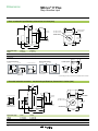
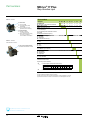
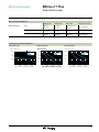
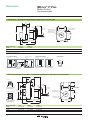
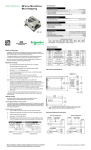
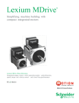
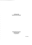
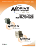
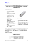
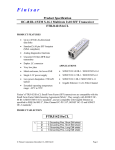
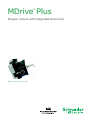
MDrive Plus ® Stepper motors with integrated electronics MDrive 17 Plus Step / direction input Description MDrive® Plus Step / direction input Presentation The MDrive® Plus with step /direction input is a 1.8° 2-phase stepper motor with on-board control electronics. Step/direction signals of a master controller, e.g. a motion controller, or A/B signals of an encoder are converted directly into motion. Settings for MDrive Plus step / direction input products may be changed on-the-fly or downloaded and stored in nonvolatile memory using the IMS SPI Motor Interface software provided. This eliminates the need for external switches or resistors. Parameters are changed via an SPI port. Application areas The MDrive Plus with step /direction input is ideal for machine builders who want an optimized motor with on-board electronics. The integrated electronics of the MDrive Plus with step /direction input reduces the potential for problems due to electrical noise by eliminating the cable between motor and drive. MDrive®Plus with step / direction input These compact, powerful and cost effective motion control solutions deliver unsurpassed smoothness and performance that will reduce system cost, design and assembly time for a large range of 2-phase stepper motor applications. Features ■ ■ ■ ■ ■ ■ ■ ■ ■ ■ ■ ■ ■ ■ Highly integrated microstepping drive and high torque 1.8° 2-phase stepper motor Advanced current control for exceptional performance and smoothness Single supply: from +12 up to +75 VDC or 120 and 240 VAC Cost effective Extremely compact 20 microstep resolutions up to 51,200 steps per rev including: Degrees, Metric, Arc Minutes Optically isolated input options: – Universal +5 to +24 VDC signals, sourcing or sinking – Differential +5 VDC signals (1) Automatic current reduction Configurable: – Motor run / hold current – Motor direction via direction input – Microstep resolution – Clock type: step and direction, quadrature, step up and step down, clockwise and counterclockwise (1) – Programmable digital filtering for clock and direction inputs Available options: – Long life linear actuators (2) – Hybrid Motion Technology™ (2) – Encoders – Control knob for manual positioning – Industrial connectors with IP54 rating (3) Several motor stack lengths available Setup parameters may be switched on-the-fly Numerous connector interface choices Graphical user interface provided for quick and easy parameter setup (1) CW / CCW input unavailable for MDrive34 or MDrive34ac products. (2) See separate documentation. (3) Industrial connectors are unavailable for MDrive14 or MDrive34 products. 2 MDrive® Plus Specifications Step / direction input Plus specifications Input power Voltage Thermal Operating temp non-condensing Temp output warning Protection Open-drain type Type Isolated input Universal Differential Digital filter range Clock types Motion VDC VAC Current maximum (2) Step frequency Resolution Heat sink Motor Number of settings Steps per revolution MDrive 14 12 to 48 — MDrive 17 12 to 48 — MDrive 23 (1) MDrive 23 (1) MDrive 34 12 to 75 12 to 60 12 to 75 — — — MDrive 34 ac — — 120 240 95 to 132 95 to 264 1A 2A 2A 3.5A 4A VAC @ VAC @ 50/60 Hz 50/60 Hz – 40° to +85°C – 40° to +75°C – 40° to +100°C – 40° to +90°C not applicable +5 to +24 VDC, 50 mA current - Thermal not applicable - Over voltage / current Voltage range: +5 to +24 VDC sourcing or sinking step clock, direction and enable Voltage range: +5 VDC clockwise and counterclockwise not applicable 50 nS to 12.9 μS (10 MHz to 38.8 kHz) Step / direction, quadrature, step up / step down, Step / direction, quadrature, clockwise / counterclockwise step up / step down 2 MHz default / 5 MHz maximum 2 MHz default 20 200, 400, 800, 1000, 1600, 2000, 3200, 5000, 6400, 10000, 12800, 20000, 25000, 25600, 40000, 50000, 51200, 36000 (0.01 deg/μstep), 21600 (1 arc minute/μstep), 25400 (0.001 mm/μstep) Setup parameters (3) SPI communication MHC MRC MSEL DIR HCDT CLK TYPE CLK IOF USER ID EN ACT WARN TEMP (4) Function Motor hold current Motor run current Microstep resolution Motor direction override Hold current delay time Clock type Clock and direction filter User ID Range 0 to 100 1 to 100 1, 2, 4, 5, 8, 10, 16, 25, 32, 50, 64, 100, 108, 125, 127, 128, 180, 200, 250, 256 0/1 0 or 2 – 65535 Step / Dir, Quadrature, Up / Down, CW / CCW 50 nS to 12.9 μS (10 MHz to 38.8 kHz) Customizable Enable active High / Low Over temperature warning 0 to 125°C Units percent percent μsteps per full step — mSec Default 5 25 — Step / Dir nS ( MHz) 1–3 characters — °C 200 nS (2 MHz) 256 CW 500 IMS High 80°C (1) Only quad stack NEMA 23 motors have +12 to +60 VDC drives, all other NEMA 23 motors have +12 to +75 VDC drives. (2) Actual power supply current will depend on voltage and load. (3) All parameters are set using the supplied IMS SPI Motor Interface GUI and may be changed on-the-fly. An optional Communication Converter is recommended with first orders. (4) Only with MDrive34 and MDrive34ac products. See User Manual for complete details: www.imshome.com/manuals.html 3 MDrive® 17 Plus Dimensions Step / direction input – Plus – mechanical specifications, dimensions in inches (mm) 1.19 (30.2) P1 0.94 ±0.02 (23.9 ±0.5) 0.08 (2.0) 0.59 ±0.02 (15.0 ±0.5) 4X M3x0.5 THREAD x0.15 MIN DEEP Ø 0.1968 +0/-0.0005 (Ø 4.999 +0/-0.013) Ø 0.866 +0/-0.002 (Ø 21.996 +0/-0.051) 2.30 (58.3) 1.220 ±0.004 ( 31.0 ±0.1) P2 0.177 ±0.002 (4.49 ±0.05) 1.68 ( 42.7) LMAX LMAX2 Motor stack length Lmax (1) Lmax2 (2) Single 2.20 (55.9) 2.79 (70.9) Double 2.43 (61.7) 3.02 (76.7) Triple 2.77 (70.4) 3.37 (85.6) (1) Single shaft. (2) Control knob or external encoder. differential encoder* P1 connector options I/O & Power P2 connector options I/O & Power I/O, Power & Communication Communication 12.0" (305mm) flying leads 7-pin non-locking spring clamp terminal strip Ø 0.97 (Ø 24.6) P1 P1 P1 single-end encoder P2 P2 0.36 (9.1) 0.44 (11.2) 12.00 +1.0/-0.0 (304.8 +25.4/-0.0) Lmax2 options None 10-pin non-locking IDC connector 12-pin locking wire crimp connector** no connector** control knob 2.04* (51.8) 1.42 (36.1) . 1.20 (30.4) . 1.22* (31.0) external encoder **12-pin locking wire crimp connector at P1 eliminates the P2 connector – Plus with industrial connector – mechanical specifications, dimensions in inches (mm) 1.38 (35.1) 0.80 (20.3) 0.49 (12.5) 0.64 (16.3) 0.94 ±0.02 (23.9 ±0.5) 0.08 (2.0) 2.792 (70.9) Ø 0.87 (Ø 22.1) Ø 0.866 +0/-0.002 (Ø 21.996 +0/-0.051) P1 1.220 ±0.004 ( 31.0 ±0.1) 1.161 (29.5) 0.177 ±0.002 (4.49 ±0.05) 19-pin M23 (male) industrial connector LMAX LMAX2 Motor stack length Lmax Lmax2 Single 2.48 (63.00) 3.15 (80.00) Double 2.71 (68.83) 3.38 (85.85) Triple 3.04 (77.22) 3.71 (94.23) 4 4X M3x0.5 THREAD x0.15 MIN DEEP 0.59 ±0.02 (15.0 ±0.5) I/O, Power & Communication Ø 0.1968 +0/-0.0020 (Ø 4.999 +0/-0.051) 1.69 ( 42.9) MDrive® 17 Plus Connectivity Step / direction input Installation accessories MDrive® Plus non-locking IDC mating connector USB connector Description Length feet (m) Part number — add "K" to part number (1) 12.0 (3.6) MD-CC300-001 12.0 (3.6) MD-CC303-001 12.0 (3.6) MD-CC301-001 ■ Mates to 12-pin locking wire crimp connector 10.0 (3.0) PD12-1434-FL3 ■ Mates to 19-pin male M23 industrial connector 13.0 (4.0) MD-CS100-000 ■ Mates to 19-pin male M23 industrial connector 13.0 (4.0) MD-CS101-000 ■ For external single-end optical encoder with 1.0 (0.3) ED-CABLE-2 ■ For external differential optical encoder with 6.0 (1.8) ED-CABLE-6 ■ 10-pin non-locking IDC connector for — CK-01 ■ 12-pin locking wire crimp connector for I/O, — CK-03 — DPM75 QuickStart Kit in-line converter For rapid design verification, all-inclusive QuickStart Kits include connectivity, instructions and CD for MDrive Plus initial functional setup and system testing. MD-CC300-001 ■ For all MDrive17 step / direction input products Communication converter MDrive® Plus 12-pin wire crimp mating connector USB connector in-line converter Electrically isolated, in-line converter pre-wired with mating connector to conveniently set/ program communication parameters for a single MDrive Plus via a PC's USB port. ■ Mates to 10-pin non-locking IDC connector ■ Mates to 12-pin locking wire crimp connector ■ Mates to 19-pin male M23 industrial connector to power & I/O MD-CC303-001 Prototype development cable MDrive® Plus 19-pin M23 mating industrial connector USB connector in-line converter to power & I/O 19-pin M23 (female) MD-CC301-001 locking mating connector Speed test/development with pre-wired mating connector with other cable end open. for I/O, communication and power with straight termination for I/O, communication and power with right angle termination for I/O, communication and power Encoder cables (2) PD12-1434-FL3 Pre-wired mating connector with other cable end open. non-locking connector 19-pin M23 (female) industrial mating connector locking connector 2.8” / 71.5 mm MD-CS100-000 Mating connector kit Connectors for assembly of cables, cable material not supplied. Sold in lots of 5. Manufacturer's crimp tool recommended for crimp connectors. communication communication and power Drive protection module Limits surge current and voltage to a safe level when DC input power is switched on-and-off to an MDrive Plus. ■ For all MDrive17 step / direction input products (1) See next page. Connectivity details: www.imshome.com/connect.html 5 Part numbers MDrive® 17 Plus Step / direction input Part numbers MDrive® 17 Plus Example: P1: I/O & Power F = 12" flying leads P = non-locking spring clamp terminal strip C = 12-pin locking wire crimp (includes I/O, Power & Comm) P2: Communication D = SPI with 10-pin IDC non-locking connector Z = None. Used with 12-pin locking wire crimp in position P1, which includes communication. MDrive® 17 Plus with industrial connector P1: I/O, Power & Communication 19-pin M23 male industrial connector K M D M 1 F S D 1 7 A 4 – E1 QuickStart Kit K = kit option, or leave blank if not wanted K M D M 1 F S D 1 7 A 4 – E1 MDrive Plus version MDM = Step / direction input K M D M 1 F S D 1 7 A 4 – E1 Input 1 = Universal input 2 = Universal input with industrial connector, IP54-rated 5 = Differential CW/CCW input (1) K M D M 1 F S D 1 7 A 4 – E1 P1 connectorF = flying leads P = pluggable C = wire crimp M = industrial connector (2) K M D M 1 F S D 1 7 A 4 – E1 Communication S = SPI K M D M 1 F S D 1 7 A 4 – E1 P2 connector (3) (4) D = IDC Z = none K M D M 1 F S D 1 7 A 4 – E1 Motor size 17 = NEMA 17 (1.7" / 42 mm) K M D M 1 F S D 1 7 A 4 – E1 Motor length A = single stack B = double stack C = triple stack K M D M 1 F S D 1 7 A 4 – E1 Drive voltage 4 = +12 to +48 VDC K M D M 1 F S D 1 7 A 4 – E1 – E1 Options Leave blank if not wanted Options may not be combined – E___ = external optical encoder with index mark (1) line count single-end part # differential part # –N 100 200 250 256 400 500 512 1000 E1 E2 E3 EP E4 E5 EQ E6 EAL EBL ECL EWL EDL EHL EXL EJL 1024 ER EYL = rear control knob for manual positioning (1) (1) Not available with industrial connector products. (2) Only available with industrial connector products. (3) Wire crimp connector at P1 includes communication, so the P2 designator is Z=none. (4) Industrial connector at P1 includes communication, so the P2 designator is Z=none. Easy MDrive part numbers via an interactive tool at: www.imshome.com/MDrivePlus.html 6 MDrive® 17 Plus Motor performance Step / direction input Motor specifications MDrive 17 Motor stack length Holding torque Detent torque Rotor inertia Weight (motor + driver) Single 32.0 oz-in / 22.6 N-cm 1.66 oz-in / 1.17 N-cm 0.00053 oz-in-sec / 0.038 kg-cm2 10.4 oz / 294.8 g Double 60.0 oz-in / 42.4 N-cm 2.08 oz-in / 1.47 N-cm 0.00080 oz-in-sec2 / 0.057 kg-cm2 12.0 oz / 340.2 g Triple 74.9 oz-in / 52.9 N-cm 3.47 oz-in / 2.45 N-cm 0.00116 oz-in-sec2 / 0.082 kg-cm2 15.2 oz / 430.9 g 2 Speed torque characteristics MDrive 17 Single stack length Torque in Oz-In / N-cm Double stack length Triple stack length Torque in Oz-In / N-cm Torque in Oz-In / N-cm 53/39 53/39 24 VDC 48 VDC 24 VDC 48 VDC 53/39 37/26 37/26 37/26 18/13 18/13 18/13 0 0 0 2000 4000 6000 (600) (1200) (1800) Speed of rotation in full steps per second (rpm) 0 2000 4000 6000 (600) (1200) (1800) Speed Speed of of rotation rotation in in full full steps steps per per second second (rpm) (rpm) 0 24 VDC 48 VDC 0 2000 (600) 4000 (1200) 6000 (1800) Speed of rotation in full steps per second (rpm) 7 Description MDrive® Plus Motion Control fully programmable Presentation The MDrive® Plus Motion Control is a 1.8° 2-phase stepper motor with on-board fully programmable motion controller, drive electronics and optional encoder. This means MDrive Plus Motion Control products are stand-alone motion control solutions that can be used without any external controller. Programming of MDrive Plus Motion Control products with RS-422/485 interface is accomplished with MCode, simple 1 to 2 character instructions, using the IMS Terminal software tool. MDrive Plus Motion Control products may also be equipped with encoders for stall detection, position maintenance and find index mark. MDrive Plus Motion Control programming for Ethernet is accomplished with the same MCode instruction set used for the RS-422/485 products. Ethernet products also support MODBUS/TCP application protocol, per specification Version 1.1b, with operation in immediate mode, not as programmable products. MDrive®Plus Motion Control, fully programmable Application areas The MDrive Plus Motion Control is ideal for machine builders who want an optimized motor with on-board electronics. The integrated electronics of the fully programmable MDrive Plus Motion Control reduces the potential for problems due to electrical noise by eliminating the cable between motor and drive. These compact, powerful and cost effective motion control solutions deliver unsurpassed smoothness and performance that will reduce system cost, design and assembly time for a large range of 2-phase stepper motor applications. Features Standard Plus ■ Highly integrated microstepping drive and high torque 1.8° 2-phase stepper motor ■ Advanced current control for exceptional performance and smoothness ■ Single supply: from +12 up to +75 VDC or 120 and 240 VAC ■ Cost effective ■ Extremely compact ■ 20 microstep resolutions to 51,200 steps/rev including: Degrees, Metric, Arc Minutes ■ Auxiliary logic power supply input ■ Open or optional closed loop control ■ Programmable motor run and hold currents ■ Four +5 to +24 VDC I/O lines accept sourcing or sinking outputs ■ One 10 bit analog input selectable: 0 to +10 VDC, 0 to +5 VDC, 0-20 mA, 4-20 mA ■ 0 to 5 MHz step clock rate selectable in 0.59 Hz increments ■ RS-422/485 or Ethernet communication protocols (1) ■ 62 software addresses for multi-drop communications (2) ■ Simple 1 to 2 character instructions ■ Available options: – Long life linear actuators (3) – Hybrid Motion Technology™ (3) – Encoders – Control knob for manual positioning – Industrial connectors with IP54 rating (4) ■ Several motor stack lengths available ■ Graphical user interface provided for quick and easy configuration and programming Expanded Plus2 ■ +24 VDC tolerant I/O sourcing or sinking, inputs and outputs with up to 8 I/O lines and electronic gearing ■ Closed loop control available with external / remote encoder option ■ High speed position capture input or trip output (1) Ethernet only available for MDrive23 products. (2) Only with RS-422/485 products. (3) See separate documentation. (4) Industrial connectors are unavailable for MDrive14 or MDrive34 products. 2 MDrive® Plus Specifications Motion Control fully programmable Standard Plus specifications Input power Voltage Thermal Operating temp non-condensing Protection Type Aux. logic input voltage Analog input Range Resolution Voltage range Number Type Logic range Output sink current Protection Type Baud rate Open loop configuration General purpose I/O Communication Motion VDC VAC Current maximum (2) Heat sink Motor Closed loop configuration (requires encoder option) Counters Software MDrive 14 12 to 48 — MDrive 17 12 to 48 — MDrive 23 (1) MDrive 23 (1) MDrive 34 12 to 75 12 to 60 12 to 75 — — — 1A 2A 2A 3.5A – 40° to + 85°C – 40° to +100°C not applicable MDrive 34ac — — 120 240 95 to 132 VAC 95 to 264 VAC 4A @ 50/60 Hz @ 50/60 Hz – 40° to +75°C – 40° to + 90°C - Thermal - Over voltage / current +12 to +24 VDC When input voltage is removed, maintains power only to control and feedback circuits. 10 bit 0 to +5 VDC, 0 to +10 VDC, 0-20 mA, 4-20 mA 4 sourcing or sinking inputs, or sinking outputs Inputs and outputs tolerant to +24 VDC, inputs TTL level compatible Up to 600 mA Over temp, short circuit, transient over voltage, over voltage, inductive clamp RS-422/485 or Ethernet (3) 4.8 to 115.2 kbps Number of settings 20 200, 400, 800, 1000, 1600, 2000, 3200, 5000, 6400, 10000, 12800, 20000, Steps per revolution 25000, 25600, 40000, 50000, 51200, 36000 (0.01 deg/μstep), 21600 (1 arc minute/μstep), 25400 (0.001mm/μstep) Encoder resolution 512 lines / 2048 edges per rev Type position, encoder / 32 bit Edge rate maximum 5 MHz Velocity Range +/- 5,000,000 steps per second Resolution 0.5961 steps per second Accel / Decel Range 1.5 x 10⁹ steps per second2 Resolution 90.9 steps per second2 Program storage Type / size flash / 6384 bytes User registers Four 32 bit User program labels & variables 192 Math functions +, –, ×, ÷, >, <, =, <=, >=, AND, OR, XOR, NOT Branch functions Branch and Call home, limit plus, limit minus, go, stop, pause, jog plus, jog minus, general purpose General purpose I/O functions Inputs Outputs moving, fault, stall, velocity change, general purpose Trip functions Trip on input, trip on position, trip on time, trip capture, trip on relative position Party mode addresses 62 (4) Encoder functions Stall detection, position maintenance, find index Expanded Plus2 specifications (5) General purpose I/O Motion Number Type Logic range Output sinking current Electronic gearing High speed I/O Closed loop configuration (requires remote encoder) 8 (or 4 when remote encoder option is selected) sourcing or sinking outputs / inputs Sourcing outputs +12 to +24 VDC, inputs and sinking outputs tolerant to +24 VDC, inputs TTL level compatible Up to 600 mA Range / resolution/ threshold – 0.001 to 2.000 / 32 bit / TTL external clock in (6) Input filter range 50 nS to 12.9 μS (10 MHz to 38.8 kHz) Range – secondary clock out (6) 1 to 1 Input filter range 50 nS to 12.9 μS (10 MHz to 38.8 kHz) Position capture Resolution 32 bit Trip output / input – 150 nS / 32 bit / TTL speed / resolution / threshold Steps per revolution Same as Standard Plus specification shown in section above Encoder type User-supplied differential encoder User-defined Encoder resolution (1) Only quad stack NEMA 23 motors have +12 to +60 VDC drives, all other NEMA 23 motors have +12 to +75 VDC drives. (2) Actual power supply current will depend on voltage and load. (3) Ethernet only available with MDrive23 Plus products. (4) Only with RS-422/485 products. (5) MDrive34ac products available only as Plus2 versions. (6) Adjusting the microstep resolution can increase the range. See User Manual for complete details: www.imshome.com/manuals.html 3 MDrive® 17 Plus Dimensions Motion Control fully programmable – Plus & Plus2 – mechanical specifications, dimensions in inches (mm) 1.19 (30.2) P1 0.94 ±0.02 (23.9 ±0.5) 0.08 (2.0) 0.59 ±0.02 (15.0 ±0.5) 4X M3x0.5 THREAD x0.15 MIN DEEP Ø 0.1968 +0/-0.0005 (Ø 4.999 +0/-0.013) Ø 0.866 +0/-0.002 (Ø 21.996 +0/-0.051) 2.30 (58.3) 1.220 ±0.004 ( 31.0 ±0.1) P2 0.177 ±0.002 (4.49 ±0.05) 1.68 ( 42.7) LMAX LMAX2 Motor stack length Lmax (1) Lmax2 (2) Single 2.20 (55.9) 2.79 (70.9) Double 2.43 (61.7) 3.02 (76.7) Triple 2.77 (70.4) 3.37 (85.6) (1) Single shaft or internal encoder. (2) Control knob or external encoder. P1 connector options I/O & Power only for Plus2 I/O & Power, Remote Encoder I/O & Power 0.44 (11.2) 12.00 +1.0/-0.0 (304.8 +25.4/-0.0) P1 12.0" (305mm) flying leads Lmax2 option P2 connector options Communication 0.20 (5.0) Communication P2 P2 Ø 0.97 (Ø 24.6) P1 P1 0.14 (3.6) 7-pin non-locking spring clamp terminal strip 10-pin non-locking IDC connector 16-pin locking wire crimp connector 10-pin friction lock wire crimp connector control knob – Plus2 with industrial connectors – mechanical specifications, dimensions in inches (mm) LMAX3 1.38 (35.1) 0.80 (20.3) Communication 0.49 (12.5) Ø 0.53 (Ø 13.5) 0.64 (16.3) 0.94 ±0.02 (23.9 ±0.5) P2 0.08 (2.0) P2: 5-pin M12 (female) industrial connector 2.792 (70.9) Ø 0.866 +0/-0.002 (Ø 21.996 +0/-0.051) P1 I/O & Power, Remote Encoder 4X M3x0.5 THREAD x0.15 MIN DEEP 0.59 ±0.02 (15.0 ±0.5) 1.078 (27.4) 1.220 ±0.004 ( 31.0 ±0.1) 1.161 (29.5) 0.177 ±0.002 (4.49 ±0.05) Ø 0.87 (Ø 22.1) P1: 19-pin M23 (male) industrial connector 1.69 ( 42.9) LMAX LMAX2 Motor stack length Lmax Lmax2 Lmax3 Single 2.48 (63.00) 3.15 (80.00) 3.08 (78.23) Double 2.71 (68.83) 3.38 (85.85) 3.31 (85.10) Triple 3.04 (77.22) 3.71 (94.23) 3.64 (92.46) 4 Ø 0.1968 +0/-0.0020 (Ø 4.999 +0/-0.051) MDrive® 17 Plus Connectivity Motion Control fully programmable Installation accessories MDrive® Plus non-locking IDC mating connector USB connector Description Length feet (m) Part number — add "K" to part number (1) QuickStart Kit in-line converter For rapid design verification, all-inclusive QuickStart Kits include connectivity, instructions and CD for MDrive Plus initial functional setup and system testing. ■ For MDrive17 Motion Control products MD-CC400-001 Communication converter MDrive® Plus 10-pin friction lock mating connector USB connector in-line converter MD-CC402-001 Electrically isolated, in-line converter pre-wired with mating connector to conveniently set/ program communication parameters for a single MDrive Plus via a PC's USB port. 12.0 (3.6) ■ Mates to 10-pin non-locking IDC connector ■ Mates to 10-pin friction lock wire crimp connector 12.0 (3.6) ■ Mates to 5-pin female M12 industrial connector 12.0 (3.6) MD-CC400-001 MD-CC402-001 MD-CC401-001 Prototype development cable MDrive® Plus 5-pin M12 mating industrial connector USB connector in-line converter Speed test/development with pre-wired mating connector with other cable end open. ■ Mates to 10-pin friction lock wire crimp connector 10.0 (3.0) PD10-1434-FL3 ■ Mates to 16-pin locking wire crimp connector 10.0 (3.0) PD16-1417-FL3 ■ Mates to 19-pin male M23 industrial connector 13.0 (4.0) MD-CS100-000 ■ Mates to 19-pin male M23 industrial connector 13.0 (4.0) MD-CS101-000 ■ 10-pin friction lock wire crimp connector for — CK-02 ■ 10-pin non-locking IDC connector for — CK-01 ■ 16-pin locking wire crimp connector for I/O, — CK-10 — DPM75 for communication for I/O, power and remote encoder option 5-pin M12 (male) MD-CC401-001 friction lock mating connector with straight termination for I/O, power and remote encoder option with right angle termination for I/O, power and remote encoder option Mating connector kit PD10-1434-FL3 locking mating connector Connectors for assembly of cables, cable material not supplied. Sold in lots of 5. Manufacturer's crimp tool recommended for crimp connectors. communication communication PD16-1417-FL3 power and remote encoder option Drive protection module 19-pin M23 (female) industrial mating connector Limits surge current and voltage to a safe level when DC input power is switched on-and-off to an MDrive Plus. ■ For all MDrive17 Motion Control products 2.8” / 71.5 mm (1) See next page. MD-CS100-000 Connectivity details: www.imshome.com/connect.html 5 MDrive® 17 Plus Part numbers Motion Control fully programmable Part numbers MDrive® 17 Plus Example: P1: I/O & Power F = 12" flying leads P = non-locking spring clamp terminal strip P2: Communication D = RS-422/485 with 10-pin IDC non-locking connector L = RS-422/485 with 10-pin friction lock wire crimp connector MDrive® 17 Plus2 P1: I/O & Power, and optional remote encoder C = 16-pin locking wire crimp connector P2: Communication D = RS-422/485 with 10-pin IDC non-locking connector L = RS-422/485 with 10-pin friction lock wire crimp connector MDrive® 17 Plus2 K M D I 1 F R D 1 7 A 4 – EQ QuickStart Kit K = kit option, or leave blank if not wanted K M D I 1 F R D 1 7 A 4 – EQ MDrive Plus version MDI = Motion Control K M D I 1 F R D 1 7 A 4 – EQ Input 1 = Plus, standard features 3 = Plus2, expanded features 4 = Plus2, expanded features, with industrial connectors, IP54-rated K M D I 1 F R D 1 7 A 4 – EQ P1 connector F = flying leads P = pluggable C = wire crimp (1) M = M23 industrial connector (2) K M D I 1 F R D 1 7 A 4 – EQ Communication R = RS-422/485 K M D I 1 F R D 1 7 A 4 – EQ P2 connector D = IDC L = wire crimp Q = M12 industrial connector (2) K M D I 1 F R D 1 7 A 4 – EQ Motor size 17 = NEMA 17 (1.7" / 42 mm) K M D I 1 F R D 1 7 A 4 – EQ Motor length A = single stack B = double stack C = triple stack K M D I 1 F R D 1 7 A 4 – EQ Drive voltage 4 = +12 to +48 VDC K M D I 1 F R D 1 7 A 4 – EQ Options Leave blank if not wanted Options may be combined, unless noted with industrial connectors P2: Communication Q = RS-422/485 with 5-pin M12 female industrial connector P1: I/O & Power, and optional remote encoder M = 19-pin M23 male industrial connector – EQ = internal encoder, 512-line internal magnetic encoder with index mark – EE = remote encoder interface, differential encoder to be provided by user Available with Plus2 versions only. May not be combined with internal encoder option. –N = rear control knob for manual positioning (3) (1) Only available with Plus2 products without industrial connectors. (2) Only available with Plus2 products with industrial connectors. (3) Not available with industrial connector products. Easy MDrive part numbers via an interactive tool at: www.imshome.com/MDrivePlus.html 6 – EQ MDrive® 17 Plus Motor performance Motion Control fully programmable Motor specifications MDrive 17 Motor stack length Holding torque Detent torque Rotor inertia Weight (motor + driver) Single 32.0 oz-in / 22.6 N-cm 1.66 oz-in / 1.17 N-cm 0.00053 oz-in-sec / 0.038 kg-cm2 10.4 oz / 294.8 g Double 60.0 oz-in / 42.4 N-cm 2.08 oz-in / 1.47 N-cm 0.00080 oz-in-sec2 / 0.057 kg-cm2 12.0 oz / 340.2 g Triple 74.9 oz-in / 52.9 N-cm 3.47 oz-in / 2.45 N-cm 0.00116 oz-in-sec2 / 0.082 kg-cm2 15.2 oz / 430.9 g 2 Speed torque characteristics MDrive 17 Single stack length Torque in Oz-In / N-cm Double stack length Triple stack length Torque in Oz-In / N-cm Torque in Oz-In / N-cm 53/39 53/39 24 VDC 48 VDC 24 VDC 48 VDC 53/39 37/26 37/26 37/26 18/13 18/13 18/13 0 0 0 2000 4000 6000 (600) (1200) (1800) Speed of rotation in full steps per second (rpm) 0 2000 4000 6000 (600) (1200) (1800) Speed Speed of of rotation rotation in in full full steps steps per per second second (rpm) (rpm) 0 24 VDC 48 VDC 0 2000 (600) 4000 (1200) 6000 (1800) Speed of rotation in full steps per second (rpm) 7