1
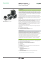
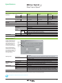
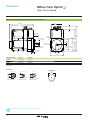
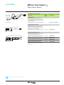
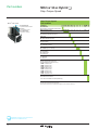
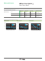
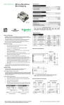
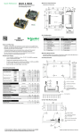
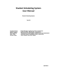
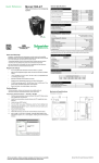
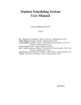
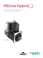
MDrive Hybrid ® Integrated motion systems with Hybrid Motion Technology™ MDrive 34ac Hybrid Step • Torque • Speed Description ® MDrive Hybrid Step • Torque • Speed Presentation The MDrive® Hybrid Step • Torque • Speed is a very compact motion system that solves many servo applications with a low cost solution. The system includes a 1.8° 2-phase stepper motor integrated with a high performance microstepping drive, internal encoder integral to system operation, and Hybrid Motion Technology™ (HMT). HMT combines the best of servo and stepper motor technologies, while delivering unique capabilities and enhancements over both. MDrive®Hybrid Step • Torque • Speed Sizes: 23, 34 & 34ac MDrive Hybrid integrated motion control systems use RS-422/485 communications. The MDrive Hybrid Step • Torque • Speed systems can be configured to operate in one of four modes: ■ Step — in Step / Direction mode, the MDrive Hybrid is controlled by an external step clock signal. ■ Torque — in Torque Control mode, the MDrive Hybrid maintains a constant, preset torque output of the motor. The torque may be set in software, or controlled via the analog input using a 0 to +5 V, 0 to +10 V or -10 to +10 V signal. ■ Speed — in Speed Control mode, the MDrive Hybrid operates as an intelligent speed control, with velocity being controlled via the analog input by a 0 to +5 V, 0 to +10 V or -10 to +10 V signal. ■ Velocity — in Velocity Control mode, the MDrive Hybrid operates at a constant velocity commanded by the slew parameter. MDrive Hybrid Step • Torque • Speed system settings are via a supplied configuration GUI featuring: ■ Easy installation via web interface ■ Automatic communication configuration ■ Tool-tips display valid range settings for each option Application areas The MDrive Hybrid is ideal for machine builders who want a low cost alternative to servo motors and brushed DC motors. The highly compact, integrated electronics of the MDrive Hybrid reduce the potential for problems due to electrical noise by eliminating the cable between motor and drive. This stepper-based system requires no tuning, and provides real-time closed loop control through an internal encoder. These compact, powerful and cost effective motion control solutions deliver unsurpassed smoothness and performance that will reduce system cost, design and assembly time for a large range of motor applications — both servo and stepper. Features ■ ■ ■ ■ ■ ■ ■ Highly integrated microstepping drive and high torque 1.8° 2-phase stepper motor HMT control for exceptional performance Internal encoder, with signals available for external use Single supply: from +12 up to +75 VDC or 120 and 240 VAC Cost effective Extremely compact 20 microstep resolutions up to 51,200 steps per rev including: Degrees, Metric, Arc Minutes ■ Several motor stack lengths available ■ Available options: – Long life linear actuator (1) – Rear control knob for manual position – QuickStart Kit – Drive Protection Module ■ Graphical user interface provided for quick and easy parameter setup (1) Only available with MDrive 23 Hybrid systems. See separate documentation. 2 Specifications ® MDrive Hybrid Step • Torque • Speed Step • Torque • Speed specifications Input power Voltage Thermal Operating temp Heat sink non-condensing Motor Open-drain type Type Temp output warning Protection Isolated input Motion VDC VAC Current maximum (1) MDrive 34 12 to 75 — MDrive 34 ac — 120 95 to 132 VAC @ 50/60 Hz 3.5A 4A – 40° to +85°C – 40° to +75°C – 40° to +75°C – 40° to +100°C not applicable – 40° to +90°C +5 to +24 VDC, 50 mA current not applicable not applicable – 40° to +90°C +5 to +24 VDC, 50 mA current - Thermal - Over voltage / current — 240 95 to 264 VAC @ 50/60 Hz Voltage range Digital filter range Clock types (Step mode) Step frequency Microstep resolution Communication MDrive 23 12 to 60 — Encoder Type Baud rate +5 to +24 VDC sourcing or sinking 50 nS to 12.9 μS (10 MHz to 38.8 kHz) Step / direction, quadrature, step up / step down 5 MHz maximum 100 ns minimum pulse width Number of settings 20 Steps per Binary 200, 400, 800, 1600, 3200, 6400, 12800, 25600, 51200, 36000 (0.01 deg/μstep), revolution 21600 (1 arc minute/μstep), 25400 (0.001 mm/μstep) Decimal 1000, 2000, 5000, 10000, 20000, 25000, 40000, 50000 Line counts 100, 200, 250, 256, 400, 500, 512, 1000 RS-422/485 4.8 to 115.2 kbps Setup parameters (2) A system configuration GUI is provided for ease of setup and configuring your device. The image (right) depicts the GUI's main screen with choice of operating mode, primary and secondary parameter settings. Operating modes Primary settings Secondary settings Note that available settings vary with each one of the three operating modes. Shown below is an overview of all settings with general descriptions. More detailed information is covered in the product manual. Operating modes Hybrid Motion Technology™ (HMT) settings General settings Defaults Step & Direction Torque Control Speed Control Setup / configuration Operation HMT status Calibration Analog Communication I/O Motion Description For point-to-point positioning, clock types: step / direction, quadrature, step up / step down Operates in relation to an analog input for positioning to torque setting Resolution: 0 – 100% Accuracy, to scale: ± 5% Operates as an independent velocity control device, no external controller required Turn HMT off / on in fixed or variable mode; set and confirm encoder line count Set control bounds for motor torque and speed, lead, lag, and make-up of lost steps Display status alerts of 8 pre-programmed fields, read-only To maintain synchronization, select options for motor’s rotor-to-stator physical position Enable active Set baud rate; enable / disable party mode and features; Check Sum integrity quality assurance Clock and filter settings; Attention Output with 11 pre-programmed fields to select among Set various motion settings which vary with the operating mode selected, ex. Current, MSEL The Speed Control Mode also includes settings for acceleration, deceleration, velocity and flags Restore system defaults or previously stored settings; view current communication settings (1) Actual power supply current will depend on voltage and load. (2) All parameters are set using the supplied system configuration GUI. An optional Communication Converter is recommended with first orders. See User Manual for complete details: www.imshome.com/manuals.html 3 Dimensions ® MDrive 34 ac Hybrid Step • Torque • Speed Mechanical specifications, dimensions in inches (mm) LMAX2 2.70 (68.4) LMAX P2 P1 P3 P1 P3 P2 0.71 (18.0) 1.46 ±0.039 (37.0 ±1.0) 6.47 (164.2) Ø 0.22 (Ø 5.5) 5.76 (146.2) 0.87 ±0.010 (22 ±0.25) 0.20 +0/-0.002 (5.0 +0/-0.05) Ø 2.87 ±0.002 (Ø 73.0 ±0.05) 2.74 +0/-0.010 ( 69.58 +0/-0.25) Ø 0.55 +0/-0.0005 (Ø 14.0 +0/-0.013) 0.08 ±0.004 (2.0 ±0.1) 0.40 (10.1) 0.63 +0/-0.017 (16.0 +0/-0.432) 3.46 (87.8) Motor stack length Lmax (1) Lmax2 (2) Single 6.1 (155.0) 7.1 (180.4) Double 6.9 (174.3) 7.9 (199.7) Triple 8.4 (214.3) 9.4 (239.7) (1) Single shaft. (2) Control knob. Connectors I/O & Encoder Lmax2 option Communication Power Ø 0.87 (Ø 22.1) Ø 0.53 (Ø 13.5) Ø 0.87 (Ø 22.1) P1: 19-pin M23 (male) industrial connector P2: 5-pin M12 (female) industrial connector P3: 3-pin Euro AC (male) industrial connector Ø 1.90 (Ø 48.3) control knob See User Manual for complete details: www.imshome.com/manuals.html 4 3.38 ( 85.8) Connectivity ® MDrive 34 ac Hybrid Step • Torque • Speed Installation accessories Description MDrive® Hybrid 5-pin M12 mating industrial connector USB connector Length feet (m) Part number QuickStart Kit in-line converter 5-pin M12 (male) MD-CC401-001 For rapid design verification, all-inclusive QuickStart Kits include connectivity, instructions and CD for MDrive Hybrid initial functional setup and system testing. ■ For MDrive34ac Step • Torque • Speed systems — add "K" to part number (1) Communication converter 19-pin M23 (female) industrial mating connector 2.8” / 71.5 mm MD-CS100-000 Electrically isolated, in-line converter pre-wired with mating connector to conveniently set/ program communication parameters for a single MDrive Hybrid via a PC's USB port. ■ Mates to 5-pin female M12 industrial connector 12.0 (3.6) MD-CC401-001 Prototype development cable Speed test/development with pre-wired mating connector with other cable end open. 3-pin Euro AC (female) industrial mating connector 2.5” / 64.5 mm MD-CS200-000 ■ Mates to 19-pin male M23 industrial connector with straight termination for I/O and encoder 13.0 (4.0) MD-CS100-000 ■ Mates to 19-pin male M23 industrial connector with right angle termination for I/O and encoder 13.0 (4.0) MD-CS101-000 ■ Mates to 3-pin male Euro AC industrial connector with straight termination for power 13.0 (4.0) MD-CS200-000 ■ Mates to 3-pin male Euro AC industrial connector with right angle termination for power 13.0 (4.0) MD-CS201-000 (1) See page 16. Connectivity details: www.imshome.com/connect.html 5 Part numbers ® MDrive 34 ac Hybrid Step • Torque • Speed Step • Torque • Speed Part numbers MDrive® 34ac Hybrid P1: I/O and Encoder 19-pin M23 industrial connector P3: Power 3-pin industrial connector P2: Communication 5-pin Euro AC connector Example: K M A M 4 M R Q 3 4 A 1 – EAM – N QuickStart Kit K = kit option, or leave blank if not wanted K M A M 4 M R Q 3 4 A 1 – EAM – N MDrive Hybrid version MAM = Step•Torque•Speed K M A M 4 M R Q 3 4 A 1 – EAM – N Type 4 = HMT with industrial connectors, IP54-rated K M A M 4 M R Q 3 4 A 1 – EAM – N P1 connector M = M23 industrial connector K M A M 4 M R Q 3 4 A 1 – EAM – N Communication R = RS-422/485 K M A M M R Q 3 4 A 1 – EAM – N P2 connector Q = industrial connector K M A M 4 M R Q 3 4 A 1 – EAM – N Motor size 34 = NEMA 34 (3.4'' / 86 mm) K M A M 4 M R Q 3 4 A 1 – EAM – N Motor length A = single stack B = double stack C = triple stack K M A M 4 M R Q 3 4 A 1 – EAM – N Drive voltage 1 = 120 VAC 2 = 240 VAC K M A M 4 M R Q 3 4 A 1 – EAM – N Encoder, differential internal encoder with index mark, signals available for external use (1) – EAM = 100 line count – EBM = 200 line count – ECM = 250 line count – EWM = 256 line count – EDM = 400 line count – EHM = 500 line count – EXM = 512 line count – EJM = 1000 line count K M A M 4 M R Q 3 4 A 1 – EAM – N Options Leave blank if not wanted – N = rear control knob for manual positioning (1) Size 34ac systems have optical encoders. NOTE: system performance is optimized with higher encoder resolution selections. Easy MDrive part numbers via an interactive tool at: www.imshome.com/MDrivePlus.html 6 –N Motor performance ® MDrive 34 ac Hybrid Step • Torque • Speed Motor specifications MDrive 34 ac Hybrid Motor stack length Holding torque Detent torque Rotor inertia Weight (motor + driver) Single 330.0 oz-in / 233.0 N-cm 10.9 oz-in / 7.7 N-cm 0.01416 oz-in-sec / 1.0 kg-cm2 6.4 lb / 2.9 kg Double 500.0 oz-in / 353.0 N-cm 14.16 oz-in / 10.0 N-cm 0.02266 oz-in-sec2 / 1.6 kg-cm2 7.7 lb / 3.5 kg Triple 750.0 oz-in / 529.0 N-cm 19.83 oz-in / 14.0 N-cm 0.04815 oz-in-sec2 / 3.4 kg-cm2 11.0 lb / 5.0 kg 2 Speed torque characteristics MDrive 34 ac Hybrid Single stack length Double stack length Triple stack length Torque in Oz-In / N-cm Torque in Oz-In / N-cm Torque in Oz-In / N-cm 700/495 120 VAC 240 VAC 700/495 120 VAC 240 VAC 700/495 500/354 500/354 500/354 300/212 300/212 300/212 100/71 100/71 0 0 2000 4000 6000 8000 (600) (1200) (1800) (2400) Speed of rotation in full steps per second (rpm) 0 120 VAC 240 VAC 100/71 0 2000 4000 6000 8000 (600) (1200) (1800) (2400) Speed of rotation in full steps per second (rpm) 0 0 2000 4000 6000 8000 (600) (1200) (1800) (2400) Speed of rotation in full steps per second (rpm) 7 USA SALES OFFICES Eastern Region Tel. 862 208-9742 - Fax 973 661-1275 e-mail: [email protected] Northeast Region Tel. 860 368-9703 e-mail: [email protected] Central Region Tel. 860 295-6102 e-mail: [email protected] Western Region Tel. 602 578-7201 e-mail: [email protected] IMS EUROPEAN SALES MANAGEMENT 4 Quai Des Etroits 69005 Lyon, France Tel. +33/4 7256 5113 - Fax +33/4 7838 1537 e-mail: [email protected] TECHNICAL SUPPORT Tel. +00 (1) 860 295-6102 - Fax +00 (1) 860 295-6107 e-mail: [email protected] Schneider Electric Motion USA 370 North Main Street, P.O. Box 457 Marlborough, CT 06447 - U.S.A. Tel. +00 (1) 860 295-6102 - Fax +00 (1) 860 295-6107 e-mail: [email protected] www.schneider-electric-motion.us © Schneider Electric Motion USA All Rights Reserved. REV10-510 Product Disclaimer and most recent product information online.