1
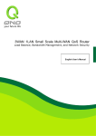
Access Point
User’s Manual
Ver1.1
30/08/2001
Wireless LAN Access Point
Access Point
User’s Manual
Ver1.1
1
Access Point
User’s Manual
Ver1.1
30/08/2001
Copyright © 2000 All rights reserved.
No part of this documentation may be reproduced in any form or by any means or used to make any derivative
work (such as translation, transformation, or adaptation) without written permission from the copyright owner.
All the other trademarks and registered trademarks are the property of their respective owners.
Statement of Conditions
The manufacturer may make improvements or changes in the product described in this documentation at any time.
The specifications and information regarding to the product in this manual are subject to change without notice.
The manufacturer assumes no responsibility for errors contained herein or for direct, indirect, special, incidental or
consequential damages with the furnishing, performance, or use of this manual or equipment supplied with it,
even if the manufacturer or its suppliers have been advised of the possibility of such damages.
Electronic Emission Notices
This device complies with Part 15 of the FCC Rules. Operation is subject to the following two conditions:
(1) This device may not cause harmful interference.
(2) This device must accept any interference received, including interference that may cause undesired operation.
FCC Radio Frequency Interference Statement
This equipment has been tested and found to comply with the limits for a class B digital device, pursuant to Part
15 of the FCC rules and Canada RSS-210. These limits are designed to provide reasonable protection against
harmful interference when the equipment is operated in a commercial environment. This equipment generates,
uses, and can radiate radio frequency energy and, if not installed and used in accordance with the instruction
manual, may cause harmful interference to radio communications. Operation of this equipment in a residential
area is likely to cause harmful interference in which case the user will be required to correct the interference at his
own expense. If the equipment causes interference to radio or television reception, try to correct the interference
by using one or more of the following measures:
• Turn the television or radio antenna until the interference stops.
• Move the equipment to one side or the other of the television or radio.
• Move the equipment farther away from the television or radio.
• Plug the equipment into an outlet that is on a different circuit from the television or radio.
To assure continued compliance, any changes or modifications not expressly approved by the manufacturer.
could void the user’s authority to operate the equipment.
FCC Radiation Exposure Statement
This equipment complies with FCC radiation exposure limits set forth for an uncontrolled environment. This
equipment should be installed and operated with the minimum distance between your body and the Antenna as
shown below:
2
Access Point
User’s Manual
Ver1.1
30/08/2001
Typographical Conventions
It is important to understand the symbol and formatting conventions used in the documentation. The following
symbols are used in the guide.
Note: Indicates a note which contains important information.
Caution: Indicates procedures which, if not observed, could result in loss of data or damage to the
equipment.
3
Access Point
User’s Manual
Ver1.1
30/08/2001
Table of Contents
1
INTRODUCTION............................................................................................................................................................. 5
1.1
FEATURES ........................................................................................................................................................................ 5
1.2
APPLICATIONS .................................................................................................................................................................. 5
1.3
SYSTEM REQUIREMENTS .................................................................................................................................................. 6
1.4
PRODUCT KIT................................................................................................................................................................... 6
2
2.1
2.2
3
UTILITY/DRIVER INSTALLATION............................................................................................................................ 7
APUTILITY ....................................................................................................................................................................... 7
2.1.1
Driver installation .........................................................................................................................................................................7
2.1.2
APUtility installation .....................................................................................................................................................................9
SNMP MANAGER .......................................................................................................................................................... 11
2.2.1
For Win98/2000/ME/NT4.0 ........................................................................................................................................................11
2.2.2
For Win95..................................................................................................................................................................................13
CONFIGURATION ........................................................................................................................................................ 14
3.1
LOCAL CONFIGURATION BY APUTILITY ......................................................................................................................... 14
3.2
REMOTE CONFIGURATION BY SNMP MANAGER ............................................................................................................. 18
4
4.1
OPERATING THE ACCESS POINT ........................................................................................................................... 28
APPLICATION.................................................................................................................................................................. 28
4.1.1
Ad-hoc configuration..................................................................................................................................................................28
4.1.2
Infrastructure configuration ........................................................................................................................................................28
4.2
OPERATING .................................................................................................................................................................... 29
4.3
CHANNELS AVAILABLE................................................................................................................................................... 31
5
TROUBLESHOOTING.................................................................................................................................................. 32
6
SPECIFICATION ........................................................................................................................................................... 36
7
GLOSSARY..................................................................................................................................................................... 37
4
Access Point
User’s Manual
Ver1.1
30/08/2001
1 INTRODUCTION
Wireless LAN is local area networking without wires, which uses radio frequencies to transmit and receive data
between PC’s or other network devices without wires or cables. Wireless LAN configurations include independent
networks, suitable for small or temporary peer-to-peer configurations, and infrastructure networks, offering fully
distributed data connectivity via micro cells and roaming.
The Access Point is designed to meet the mobility, performance, security, interoperability, management, reliability
requirements of IEEE 802.11b high data rate standard and IEEE 802.3 Ethernet 10 Base-T standard. When
installed, Access Point can communicate with other IEEE 802.11b and IEEE 802.3 compatible products to create
a wireless network in your office or home.
1.1 Features
Compliant with 11 Mbps 802.11b high-speed specification
Data rate 11/5.5/2/1 Mbps automatic fallback under noisy environment
Supports a wide range of OS (Win95/98/2000/ME/NT)
Interoperable with IEEE 802.11b compliant equipment
Interoperable with IEEE 802.3 compliant equipment
Supports full mobility and seamless roaming from cell to cell
Working range up to 300M under open environment.
Supports point-to-point and point-to-multipoint access.
Direct Sequence Spread Spectrum (DSSS) technology provides robust, interference-resistant and secure
wireless connection.
Wireless connection without the hassles and cost of cabling.
Support access point bridging functions.
Remote/local management by the Ethernet/USB.
Automatic diversity antennas.
1.2 Applications
Home networking for device sharing - Remote access to corporate network information E-mail, file transfer
and terminal emulation.
Frequently changing environments - Retailers, manufacturers and banks who frequently rearrange the
workplace and change location.
SOHO (Small Office and Home Office) users - SOHO users need easy and quick installation of a small
computer network.
Inter-building connection - The wireless building-to-building network installs quickly, requires no monthly
lease fees, and provides the flexibility to reconfigure easily.
Hard-to-wire buildings - Historical or old buildings, asbestos installations, and open area where wiring is
difficult to employ.
Education (ex/ campuses)
5
Access Point
User’s Manual
Ver1.1
30/08/2001
Hospitals/Medical offices - Doctors, nurses, and white-collar workers need access to database while being
mobile in the hospital.
Warehouse (inventory)
Security huts
Exhibition centers
Temporary LANs for special projects or peak time - Trade shows, exhibitions, retailers, airline and shipping
companies need additional workstations for a peak period. Auditors require workgroups at customer sites.
1.3 System Requirements
Below lists minimum requirement to use Access Point access point:
1.
LAN with a 10/100 Base-T (UTP) Ethernet cable drop (RJ-45 connector).
2.
An A/C power outlet (100~240V, 50~60Hz)
3.
At least one IEEE 802.11 or IEEE 802.11b standard Wireless LAN NIC (Network Interface Card).
1.4 Product Kit
Access Point includes the following items. If any listed item is not included, please contact your local dealer.
1. Wireless Access point x 1
2. Driver & Utility CD-ROM Disk x 1
3. User’s manual x 1
4. AC adapter with power cable x 1.
5. Antenna x 2.
6
Access Point
User’s Manual
Ver1.1
30/08/2001
2 UTILITY/DRIVER INSTALLATION
You can operate Access Point by default configuration directly. If you want to configure it by yourself, you will need
to install either APUtility and relative USB driver for local configuration, or SNMP (Simple Network Management
Protocol) manager for remote configuration.
This manual will demonstrate the installation in Windows 98 system.
2.1 APUtility
Below lists the minimum requirements to install APUtility:
1. PC with Utility/Driver CD-ROM Disk (included by this product kit), USB port and cable.
2. Win98//2000/ME operating system.
3. Minimum 5 Mbytes free disk space for installing driver and utility program
The Driver will not be enabled on Win95/NT
2.1.1
Driver installation
1. Boot up your PC and power Access Point
2. Insert Utility/Driver CD-ROM Disk into drive.
3. Connect USB cable between PC and Access Point
4. Windows will display a "New Hardware Found" message indicating that Windows has recognized a new USB
device that has not been used before. Click Next>.
7
Access Point
User’s Manual
Ver1.1
30/08/2001
5. Instruct Windows to "search for the best driver" and click Next>.
6. Make the appropriate selection depending on where the drivers are located (e.g. D:\Driver) and click Next>.
7. Windows will confirm the driver location you selected. You only need to press next or back to change the
location. click Next>.
8
Access Point
User’s Manual
Ver1.1
30/08/2001
8. A dialog will appear that will confirm the completion of the procedure. Click Finish to exit.
After the installation of the driver is complete, unplug the cable and then plug it again.
2.1.2
APUtility installation
1. Double click D:\Utility\APUtility\SETUP.EXE
2. Click Next>.
3. Click Yes if you agree with the statements.
9
Access Point
User’s Manual
Ver1.1
30/08/2001
4. Browse the folder you want to install, and then click Next>.
5. Select the installation type, then click Next>.
6. Specify program folder name, then click Next>.
10
Access Point
User’s Manual
Ver1.1
30/08/2001
7. Click Finish to exit.
2.2 SNMP Manager
2.2.1
For Win98/2000/ME/NT4.0
1. Double click D:\Utility\SNMP\SETUP.EXE
2. Click Next>.
3. Click Yes if you agree with the statements.
11
Access Point
User’s Manual
Ver1.1
30/08/2001
4. Browse the folder you want to install, and then click Next>.
5. Select the installation type, then click Next>.
6. Specify program folder name, then click Next>.
12
Access Point
User’s Manual
Ver1.1
30/08/2001
7. Click Finish to exit.
2.2.2
For Win95
1. FIRST , DOWNLOADING DCOM95 ,THEN INSTALL IT IS REQUIRED BEFORE THE INSTALLATION OF SNMP MANAGER .
LINK MICROSOFT W EBSITE TO DOWNLOAD DCOM95 1.3
(HTTP://WWW.MICROSOFT.COM/COM/DCOM/DCOM95/DOWNLOAD.ASP).
2.
SECOND , INSTALL W INDOWS SOCKET 2 UPDATE(W95WS2SETUP.EXE) FOR W IN95 . THE FILE CAN BE
DOWNLOADED FROM THE MICROSOFT W EBSITE :
(HTTP://WWW.MICROSOFT.COM/WINDOWS/DOWNLOADS/BIN/W95WS2SETUP.EXE).
3. Finally , please refer to section 2.2.1 For Win98/2000/ME/NT4.0 , this is the same steps to install SNMP
Manager.
13
Access Point
User’s Manual
Ver1.1
30/08/2001
3 CONFIGURATION
In this section, the detail local and remote configuration will be demonstrated.
3.1 Local configuration by APUtility
If you want to change or view the parameters of Access Point, you have to plug the USB cable from PC (where
APUtility driver and utility had been installed) to the Access Point USB port.
1. Run the APUtility from “Start “, “Program”, “AP UTILITIES”,”APUtility”.
2. Click the “Configuration” button.
3. A Bridge Configuration window will appear as shown below. In the window that it will appear you have four
options
14
Access Point
User’s Manual
Ver1.1
30/08/2001
4. Configuration Settings: Select the “Configuration Settings” option and Press the “Get” button if you want to
view the current parameters. If you want to set new parameters, first select the required parameter, press the
“Modify” button and then type the new value. You will have to press the “Set” button to download any changes
to the bridge.
Parameters:
MAC Address: The MAC Address of the AP.
Regulation Domain: You need to select the Regulation Domain among the following options, FCC, ETSI,
SPAIN, DOC, SPAIN, FRANCE and MKK.
Ethernet IP Address: The IP Address of the AP.
Ethernet Subnet Mask: The Ethernet station and the Access Point must be on the same subnet. The IP
address for the Access Point must correspond to the Subnet Mask.
Wireless MAC Address: The wireless MAC address of the AP.
ESSID: Select the ESSID to be used.
ESSID Length: The length of the ESSID (number of characters).
Auto Rate Fall Back: Select Enable or Disable.
Wireless Channel: Select the channel to be used. There are 14 channels available.
WEP type: The Wired Equivalent Privacy Algorithm (64 or 128 bits).
WEP key:The WEP key if the WEP option is enabled in order to activate WE Pencryption for transmissions
between the stations and the Access Point.
Wireless Fragmentation Threshold: This is the option for the Fragmentation Threshold activation.
Wireless RTS Threshold: This is the option for the RTS Threshold activation.
WEP Keys #1 - #4: The default key that will be used. May be edited only if WEP type is 64 bits.
WEP keys must be in HEX and in two bytes per character format e.g. if you want the WEP Key #1 to be
12345, then you must set it as 0102030405.
Preamble Type: Select Short or Long Preamble Type.
Authentication Type: Select Open System or Shared Key Authentication Type.
Access Point Name: Type the Access Point’s name (Product code).
Operational Rate Set: Select the Operational Rate set among the following options, 82 84 8B 96 (1 - 2 - 5.5 11 Mbps) or 82 84 0B 16 (1 - 2 Mbps).
Beacon Period: Set the Beacon Period parameter.
DTIM: Set the DTIM parameter.
Receive Antenna: Set the Receive Antenna among the following options Left, Right or Diversity.
Transmit Antenna: Set the Transmit Antenna among the following options Left, Right or Diversity.
Operational Mode: Set one of the following operational modes os the Access Point.
• Access Point
• Access Point Client
• Wireless Bridge
15
Access Point
User’s Manual
Ver1.1
30/08/2001
User Community: Indicates the user’s password. The default pasword is “pulic”
User Access: Indicates the user’s access rights. The user can only read and not set or change the AP’s
parameters.
Administrator Community: Indicates the administrator’s password. The default password is “public”
Administrator Access: Indicates the Administrator’s access rights. The administrator can read and also set or
save changes to the AP’s parameters.
Manufacturer Community: Indicates the manufacturer’s password.
Manufacturer Access: Indicates the manufacturer’s access rights. The manufacturer can read and set or
save changes to the AP’s parameters. Also can view or modify the Hardware Configuration.
Gateway IP Address: Network Gateway
IP Filtering: Enable/Disable the possibility to allow only IP protocol packets to pass through the WLAN and
any other protocol packets filtered out.
DHCP client: Enable/Disable automatic IP adress assigment by the DHCP server Primary Port: Determines
the Access Point;s MAC and IP Address.
Primary Port: The interface which determines the DHCP server (EthernetPort/Wireless Port).
Authorization Algorithm: Enable/Disable the association with authorized MAC Addresses stations.
SNMP traps: Enabled/Disabled SNMP traps, which are the messages indicating the actions related to the AP
that have taken place.
Preferred BSSID: Remote MAC Address for connection, in Access Point Client or Wireless Bridge
Operational modes.
WEP 128 keys #1-#4: The default key that will be used. May be edited if WEP type is 128 bits.
5. CR31 Settings: By selecting the “C31 Settings” option, you can get or set the Transmitting Power values for
the Control Register 31 of the Base-band, for each channel.
16
Access Point
User’s Manual
Ver1.1
30/08/2001
6. Default Settings: Load the default values of the Access Point by selecting this option.
17
Access Point
User’s Manual
Ver1.1
30/08/2001
7. Manufacturer Settings: View or change the Manufacturer Settings by selecting this option.
This option is used only for manufacturing purposes.
3.2 Remote configuration by SNMP manager
You can configure Access Point via Ethernet by PC with SNMP Manager installed.
1. Run the SNMP Manager from “Start “, “Program”, “AP UTILITIES”,”SNMP Manager”.
18
Access Point
User’s Manual
Ver1.1
30/08/2001
2. Select “Connect to Access Point” option which is under the “File” menu. Try to connect to the Access Point, by
typing its IP address in the panel which appears and at the Community field, type "public" and then press OK.
3. If you don’t know the IP address of the Access Point you can use the “Find Access Point” option which is also
under the “File” menu in order to see the Access Points available for connection. Select one of the available
Access Points and press “Connect”.
4. In case of a successful connection to the Access Point, the following window appears
19
Access Point
User’s Manual
Ver1.1
30/08/2001
In case of an unsuccessful connection you receive the following message.
If the above error message appears, you need to check if the AP has the desired IP Address and is connected to
the network. In order to check the validity of the IP Address you need to ping the AP.
5. When the connection has successfully been established, you get a message in the left bottom corner
indicating “Get Configuration done” and on the right corner the “IP Address” of the connected Access Point.
As soon as the connection has been established, you are now able to start viewing or setting the Access Point
parameters.
Under the “File” menu ,the file menu contains the following enabled submenus
• Close Connection AP - Terminates the connection with the Access Point.
• Download Changes - When all the desired values of the parameters have been set
you are able to download the changes (save the changes) to the Access Point by
selecting this submenu.
• Options - Defines the polling interval according to which the SNMP Manager polls
the Access point in order to update the statistics and the Associated Stations
6. Under the “Setup” menu, there are three options available:
Bridge
Wireless LAN
Enable SNMP Traps
Authorization
20
Access Point
User’s Manual
Ver1.1
30/08/2001
• Bridge - Under the “Bridge” submenu, there are two options:
IP Configuration:Under the “Bridge” option, there is the submenu “IP Configuration”. The “Ethernet Address”,
The “IP Address” and “IP Mask” can also be modified through the “IP Configuration”, if DHCP client is not
enabled. If DHCP client is enabled the IP Address field displays the IP Address that was dynamically
assigned to the AP by the network DHCP server and the IP Mask field displays the IP Mask utilized by the
network DHCP server. Additional you have to select the Primary Port which is the interface that determines
the DHCP server. If changes are made, you need to “Download Changes” under the “File” menu in order to
save them.
Filtering: If the IP Routing is enabled only the IP protocol packets will pass through
the WLAN and any other protocol filtered out
7. Under the “Wireless LAN” option, the following submenus are available:
Privacy Options
Operational settings
21
Access Point
User’s Manual
Ver1.1
30/08/2001
Authorized Mac Address
22
Access Point
User’s Manual
Ver1.1
30/08/2001
Privacy Options: By choosing this option you must define the encryption key values of your choice. There are four
5 Hex digit encryption keys available if you select 64bit WEP or there are four 13 Hex digit
encryption keys available if you select 128bit WEP. The key is enabled only if you select it in the
“Default key” option . Enable the WEP (Wired Equivalent Privacy) option in order to activate
WEP encryption for transmissions between the stations and the Access Point. WEP
is an authentication algorithm which protects authorized Wireless LAN users against
eavesdropping.
Operational Settings: You can either view or modify the following Values:
ESSID: Select the ESSID to be used.
Channel: Select the channel to be used. There are 13 channels available.
Fragmentation: This is the option for the Fragmentation Threshold activation.
23
Access Point
User’s Manual
Ver1.1
30/08/2001
RTS Threshold: This is the option for the RTS Threshold activation.
Authentication Type: Select Open System, Shared Key, or Both
Open System: With this setting any station in the WLAN can associate with an
Access Point and receive and transmitted data (null authentication).
Shared Key: With this setting only stations using a shared key encryption identified
by the Access Point are allowed to associate with it.
Both: with this setting stations communicate with the Access Point either with or
without data encryption.
Preamble Type (Short, Long).
Rate: Select the basic rates to be used among the following options 1 - 2 (Mbps), 1 - 2- 5.5 - 11 (Mbps).
Auto Rate Fall Back: When this is enabled the transmission rate is defined by the past transmission status.
If you press the Advanced button , there are the following three opera-tional
modes available.
Access Point: This mode provides access for wireless stations to wired LANs and
from wired LANs to wireless stations. Furthermore, wireless stations within the
range of the Access Point device may communicate with each other via the Access
Point.
Acess Point Client: This mode allows the connection of one or more remote LANs
with a central LAN, creating thus an extended single virtual LAN. In this way, any station of the Remote
LAN can successfully communicate with any station of the central LAN, as if all of them belonged to the
same physical LAN. Wireless Stations can’t associated with Access Point Clients. The Access Point
conducts the designated traffic to the appropriate wired or wireless station.
• Preferred BSS: It is enabled only if you select the Access Point Client option. BSS
corresponds to the MAC Address of the desired AP.
Wireless Bridge: This mode allows two types of connections.
a. Point to Point: The Wireless Bridge can communicate with a specific Remote
MAC Address.
• Remote MAC Address: It is enabled only if you select Point to Point. It corresponds
to the MAC Address of the Wireless Bridge of the Remote LAN.
b. Point to Multipoint: The Wireless bridge can communicate with any Wireless
Bridge available in the same channel. When Authorization Algorithm (see the next
menu - Authorized MAC Address), is enabled, the Wireless Bridge can communicate with any
Wireless Bridge whose MAC Addresses exists in the Authorization Table.
24
Access Point
User’s Manual
Ver1.1
30/08/2001
The value “Regulation Domain” is already set and cannot be modified.
Authorized MAC Address : For security reasons the Access Point has the ability to associate with authorized
MAC Addresses stations, if the Authorization Table option is enabled .Thus, under the Authorized MAC
Address option you may press the following buttons.
The “Load file” button in order to load a file with the MAC Addresses that can be
associated with the Access Point (Authorized MAC Addresses).
The “Download” button in order to download the Authorized MAC Address to the
Access Point.
The “Get” button in order to get from the Access Point the Authorized MAC
Addresses.
8. Under the “Setup” menu you can either enable or disable SNMP traps, which are messages displayed in the
left bottom corner indicating that an action related to the AP–Bridge took place, such as:
Trap Reassociation: This trap message is sent when a Station’s reassociation request is received from the
AP - Bridge.
Trap Association: Indicates the reception of an association request packet and the sender Station's
successful association with the Wireless Bridge.
Trap Disassociation: This trap message is sent when a disassociation notification packet is received from a
Station.
Trap Reset: This trap message is sent when the AP-Bridge resets. • Trap Setting IP Address with Ping: This
trap message is sent when the AP-Bridge IP address is set with the transmission of a ping message.
Trap Start Up: This trap message is sent when Bridge starts up.
25
Access Point
User’s Manual
Ver1.1
30/08/2001
Trap Failed To Erase Flash: This trap message is sent when Bridge fails to erase flash.
9. Authorization - Using this submenu the Administrator can change the passwords
which referred to the community field for the User and the Administrator Authority
10. The other menus :
Commands menu: Under this menu there are two submenus.
• Reset Device - You can reset the Access Point. This action takes place after a user
makes configuration changes in order to initiate the changes.
• Restore Default - You can restore the factory default values of the Access Point.
Info menu:
Wireless statistics: This submenu reports the statistics concerning the unit’s Wireless
activity
Ethernet statistics: This submenu reports the statistics concerning the unit’s Ethernet
port activity .The meaning of the fields,
Traps menu: Provides information for trap messages
• View Record - You can see additional information for every Trap Message
Network menu: Provides information about the Network. Under this menu there is only
the Associated Station submenu.
• Associated stations - Using this submenu you can view the MAC Addresses of the
Associated stations with the Access Point.
Window menu: Under this menu there are the following submenus
• Cascade - All opened windows are arranged on the desktop in a cascade fashion.
• Tile - All open windows are visible on the desktop.
26
Access Point
User’s Manual
Ver1.1
30/08/2001
Help menu: Provides on line help about the application.
27
Access Point
User’s Manual
Ver1.1
30/08/2001
4 OPERATING THE ACCESS POINT
4.1 Application
4.1.1
Ad-hoc configuration
An Ad-Hoc wireless LAN is a group of computers, each equipped with one TWL-C11 adapter, connected as an
independent wireless LAN. Computers in a specific Ad-Hoc wireless LAN must be configured at the same radio
channel. Ad-Hoc wireless LAN is applicable at a departmental scale for a branch or SOHO operation.
Notebook with TWL-C11
Notebook with TWL-C11
Desktop PC with TWL-U11
Ad-Hoc Configuration
4.1.2
Infrastructure configuration
Access Point provides access to a wired LAN for wireless workstations. An integrated wireless and wired LAN is
called an Infrastructure configuration. A group of TWL-C11 PC users and an Access Point construct a Basic
Service Set (BSS). Each TWL-C11 PC in this BSS can talk to any computer in the wired LAN infrastructure via
the Access Point.
Infrastructure configuration not only extends the accessibility of a TWL-C11 PC to the wired LAN, but also doubled
the effective wireless transmission range for 2 TWL-C11 PCs. Since Access Point is able to forward data within
its BSS, the effective transmission range in an infrastructure LAN is doubled.
BSS ID is, in essential, the ID of each independent TWL-C11. All TWL-C11 PCs configured without roaming
options in this independent BSS must be configured with BSS ID of that Access point. Check your Access Point
for its BSS ID or use the Access Point Browser Utility program.
28
Access Point
User’s Manual
Ver1.1
30/08/2001
Infrastructure is applicable to enterprise scale for wireless access to central database, or wireless application for
mobile workers.
Two Access Points could be used as a point-to-point link between two LANs. LAN-Interconnection is applicable to
a wireless backbone between buildings.
Desktop PC
Desktop PC
File Server
Hub
... ..
... ..
TWL-A11
TWL-A11
Notebook with TWL-C11
Notebook with TWL-C11
Desktop PC with TWL-U11
Desktop PC with TWL-U11
Notebook with TWL-C11
Notebook with TWL-C11
BSS1
BSS2
ESS
4.1.2.1
Roaming
An Infrastructure configuration also supports roaming capability for mobile workers. More than one BSS can be
configured as an Extended Service Set (ESS). On account of a continuous connection to the network, users
within this ESS could roam freely. All TWL-C11 PCs and Access Point within one ESS must be configured with
the same ESS ID and at the same radio channel.
Before setting up an ESS for roaming, it would be helpful to improve the performance by choosing a feasible radio
channel and right places for Access Points.
4.2 Operating
1. Power on Access Point plugging power adapter, and connect Ethernet cable into RG-45 connector.
2. The four LED’s show the status of Access Point.
Link & Activity of Ethernet
29
Access Point
User’s Manual
Ver1.1
30/08/2001
Full duplex operation of Ethernet
DC Power of Access Point
Clear Channel Assessment of air
3. Insert the wireless LAN Card into the PC slot until it seats snugly. Arrows on the front of the PC Card indicate
the insertion direction.
Make sure the mode of wireless LAN Card shall be set to infrastructure. And the SSID shall be the same
as Access Point.
4. Now, you will be able to operate your notebook just like you are connected with your local area network
without wiring.
30
Access Point
User’s Manual
Ver1.1
30/08/2001
4.3 Channels available
The following lists the allowable channels in some country for your reference.
Frequency (MHz)
2412
2417
2422
2427
2432
2437
2442
2447
2452
2457
2462
2467
2472
2484
FCC (US)
1
2
3
4
5
6
7
8
9
10
11
-
IC (Canada) ETSI (Europe)
1
1
2
2
3
3
4
4
5
5
6
6
7
7
8
8
9
9
10
10
11
11
12
13
-
31
Spain
10
11
-
France
10
11
12
13
-
MKK (Japan)
1
2
3
4
5
6
7
8
9
10
11
12
13
14
Access Point
User’s Manual
Ver1.1
30/08/2001
5 TROUBLESHOOTING
Q1 Weak signal or intermittent
connection.
1 - Keep the area around the antenna clear from materials that could block
radio transmission, such as metal objects, electronic devices, and cordless
telephones.
- Change the direction of the antenna slightly.
- Move your notebook computer a few inches to find a better signal.
2 Use you site survey utility (by wireless LAN Card utility) to survey a better
location and orientation for a network connection.
Q2 PC cannot attach to the
network.
1 Verify that the adapter Wireless LAN Service Area ID matches the access
point ID
2 Verify that the adapter Data Rate is configured properly for the access
point.
Q3 Does the AP have
The AP has two connectors for external antennas.
provision for external high
gain antenna?
Q4 For what do the AP use two
antennas
Q5 What external antenna
This is the antenna diversity, it can increase the receive sensitivity of
Access Point.
It is SX connector. SX to SMA adapter is available
connector type? e.g. SMA
or reverse polarity SMA?
Q6 It is possible to connect two
directional antennas to both
You can attach certified antenna with the same connector (SX type) with
AP
Ap's. How is it might work
Q7 What about operating range -
Based on specification, the power margin can support communication
450 m. ? What kind of
distance as long as 450 m in free space theoretically. But due to the fading
antennas do you used. Maybe
loss of atmosphere, the practical link distance of line-of-sight will be around
you have some good supplier
150 ~ 300 m (depends on weather, surroundings and antenna orientation).
of external antennas which
Of course, this range can be extended by directional antenna.
could extend a operating
range?
Q8 Does building to building
mode support Multi-point to
Multi-point with repeating
capability?
Q9 Will the AP, in 'normal'
mode, support Routing
between different
networks?
Yes
No
32
Access Point
User’s Manual
Q10 Does the AP support
PPPoE, which is widely
used in HK for broadband
access?
Q11 Does the AP support
multiple access through a
single login session?
Q12 Are you intending to
provide WEB based drivers
for your products?
Q13 We have spent several
hours attempting to
configure theses access
pionts. One of our two units
will not hold the IP
address. It reverts back to
the factory address starting
with 10
Q14 The second AP unit
however refused to hold
the IP address assigned
even after repeated
downloads of the
configuration and also the
SNMP configuration
refused to connect or even
acknowledge the unit.
Ver1.1
30/08/2001
Point-to-Point Protocol over Ethernet (PPPoE) relies on two widely accepted
standards: PPP and Ethernet. PPPoE is a specification for connecting the users
on an Ethernet to the Internet through a common broadband medium, such as a
single DSL line, wireless device or cable modem. All the users over the
Ethernet share a common connection, so the Ethernet principles supporting
multiple users in a LAN combine with the principles of PPP, which apply to
serial connections. PPPoE is upper layer protocol, and can be supported by our
WLAN products
This feature is handled by server, but not WLAN. That means if your sever
support it, it has no problem with WLAN.
Yes, we are planning to add web server function into AP, but the schedule is
not determined yet.
After you change IP, please make sure you download this change.
Save the configuration by selecting “Download Changes” under the
“File” menu. The IP address of the access point has now been set
permanently.
There are two possibilities.
(1) The default IP setting is the same for each AP. Connecting
two or more AP's simultaneously onto LAN will results the
conflict problem. Please modify the IP setting by SNMP (make
sure no other AP with the same IP on the LAN you connect) or
APUtility first.
(2) If you can find the AP by SNMP but can not connect to it,
this is caused by the conflict between IP & MAC.
Please follow below steps to resolve it.
Please plug the USB cable to the Access Point USB port. Run
the Bridge APUtility and select the “Configuration” button. You
will see the MAC address at first line.
Follow the steps below giving the Access Point a temporary
address at the beginning (Step A) and saving the IP address
through the SNMP Manager application (Step B).
33
Access Point
User’s Manual
Ver1.1
30/08/2001
Step A:
1.
Connect an Ethernet station and the Access Point on the
same subnet. The simplest way to accomplish that is to connect
the Access Point and the Ethernet station to the same hub. You
need to check if the station IP address and the Sub-net mask
are configured properly. Also the new IP address for the Access
Point must correspond to the Subnet mask.
2.
Open a MS-DOS Prompt window and enter a static route
in the arp table for the
new IP address you want to assign.
Use the arp -s command to do that: arp -s "new-IP-address"
"AP-MAC-address"
For example: arp -s 10.170.254.27 00-00-22-22-22-25
3.
Ping the Access Point, using its new IP address.
For example: ping 10.170.254.27
4.
If you get a ping reply, then the IP address has been
temporarily set. In order to set it permanently you need to
proceed to Step B without powering off the Access Point.
Step B:
1.
Open the SNMP Manager application.
2.
Connect to the access point by selecting the “Connect
AP-Bridge” option under the “File” menu. Type the IP address
of the access point (which has been temporarily set in Step A)
in the panel which appears, type “public” at the Community
field, and then press OK. The SNMP Manager will inform you
that the access point has been found and that all the
configuration values have been retrieved.
3.
Under the “Setup” -> “Bridge” submenu, select “IP
Configuration”. Type the IP address of Step A in the
configuration window that appears. Confirm the validity of the
other values (Ethernet Address and IP Mask) and press “OK”
4.
Save the configuration by selecting “Download Changes”
under the “File” menu. The IP address of the access point has
now been set permanently.
34
Access Point
User’s Manual
We plan to use AP to built
radio backbone network. End
user's will be grouped in few
cable LAN's. This LAN's we
plan radio backbone-connect
using your AP's. What do you
think about this?How is it
work?
Ver1.1
30/08/2001
It is wireless bridge configuration of our AP,it work as following figure,
35
Access Point
User’s Manual
Ver1.1
30/08/2001
6 SPECIFICATION
General
Standards compliance
Security
IEEE 802.3 and 802.11b
WEP 128 bit, encryption RC4
Hardware
RF
Data rate
Modulation
Coding
Number of channels
Host interface
Transmit power
Receive sensitivity
Power
Software
OS Supported
Management interface
Mechanical
Antenna
Indicator
Environmental
Dimensions
Weight
Certificate
EMC
Frequency range: 2.4 ~ 2.4835 GHz
11 Mbps / 5.5 Mbps / 2 Mbps / 1 Mbps
DSSS (Direct Sequence Spread Spectrum)
DBPSK/DQPSK
1, 2 Mbps: 11 chip/bit Barker Coding
5.5, 11 Mbps: Complementary Code Keying
Europe: 13 (3 non-overlapping)
US: 11 (3 non-overlapping)
France: 4 (1 non-overlapping)
Japan: 14 (3 non-overlapping)
RJ-45
USB (local configuration)
+15 dBm (Typ.)
-83 dBm (Typ.) for 11Mbps; -88 dBm (Typ.) for 5.5/2/1 Mbps; (@BER 10E-5)
<500mA @ 5Vdc
Win95/98/2000/ME/ NT
Local: USB
Remote: SNMP
Auto: DHCP Client
Two SX connectors for external antennas
Power, CCA, activity, and duplex
0 - 55°C (operation) , -10 ~ +85°C (storage)
Relative Humidity 95% (non-condensing)
167.0 x 117.5 x 35.5 mm (w/o antenna)
Less than 350 g (excluding power adapter)
U.S., Canada: FCC Part 15, sections 15.247, 15.205, 15.209; RSS-210
Europe: ETS 300 328, ETS 300 826, CE Marked
Japan: AIRB STD T-66, D-33
36
Access Point
User’s Manual
Ver1.1
30/08/2001
7 GLOSSARY
Access Point - Any entity that has station functionality and provides access to the distribution services, via the
wireless medium (WM) for associated stations.
Ad-Hoc - A network composed solely of stations within mutual communication range of each other via the
wireless medium (WM). An ad hoc network is typically created in a spontaneous manner. The principal
distinguishing characteristic of an ad hoc network is its limited temporal and spatial extent. These limitations allow
the act of creating and dissolving the ad hoc network to be sufficiently straightforward and convenient so as to be
achievable by non-technical users of the network facilities; i.e., no specialized technical skills are required and little
or no investment of time or additional resources is required beyond the stations that are to participate in the ad
hoc network. The term ad hoc is often used as slang to refer to an independent basic service set (IBSS).
BSS (Basic Service Set) - An Access Point associated with several wireless stations.
ESS (Extended Service Set) - More than one BSS can be configured as an Extended Service Set. An
ESS is basically a roaming domain.
Ethernet - A popular local area data communications network, originally developed by Xerox Corp., which accepts
transmission from computers and terminals. Ethernet operates on 10 Mbps baseband transmission over shielded
coaxial cable or over shielded twisted pair telephone wire.
Infrastructure - The infrastructure includes the distribution system medium (DSM), access point (AP), and portal
entities. It is also the logical location of distribution and integration service functions of an extended service set
(ESS). An infrastructure contains one or more APs and zero or more portals in addition to the distribution system
(DS).
PCMCIA (Personal Computer Memory Card International Association) - It develops standards for PC cards,
formerly known as PCMCIA cards, are available in three “types” which are about the same length and width as
credit cards, but range in thickness from 3.3 mm (Type I) to 5.0 mm (Type II) to 10.5 mm (Type III). These cards
can be used for many functions, including memory storage, as landline modems and as wireless LAN.
Roaming - A function that allows one to travel with a mobile end system (wireless LAN mobile station, for example)
through the territory of a domain (an ESS, for example) while continuously connecting to the infrastructure.
RTS (Request To Send) Threshold – Transmitters contending for the medium may not hear each other.
RTS/CTS mechanism can solve this “ Hidden Node Problem”.
Wired Equivalent Privacy (WEP) - The optional cryptographic confidentiality algorithm specified by IEEE 802.11
used to provide data confidentiality that is subjectively equivalent to the confidentiality of a wired local area network
(LAN) medium that does not employ cryptographic techniques to enhance privacy.
37
Access Point
User’s Manual
Ver1.1
30/08/2001
This page is blank.
38
Access Point
User’s Manual
Ver1.1
30/08/2001
P/N: 58151051P
39