1
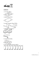
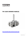
TM-CAGE OWNERS MANUAL
www.visionaudiovisual.com/techmount/tm-cage
1
TM-CAGE_manual_en_v1
TM-CAGE OWNERS MANUAL
Thanks for choosing the Vision TM-CAGE Techmount! In order to obtain the best performance
please be sure to read this owner’s manual and use your product only in accordance with the
instructions.
WARNINGS
During installation take care to adhere to workplace health and safety laws:
• Attach the bracket to a rated load-bearing structure.
NEVER MOUNT CAGE OR BRACKET DIRECTLY TO A FALSE CEILING!
• Do not cut or drill any parts above head height. This should all be done using the correct
safety equipment at floor level. It can be attached to brick/masonry ceilings.
• Avoid overstretching which might result in the ladder tipping over.
• SWL (safe working load): 7kg
• The TM-CAGE is a projector security cage which is designed to fix to a load-bearing ceiling or
wall with Vision’s projector brackets.
• Ensure it is installed in an appropriate place – for example not obstructing an emergency exit.
• Ensure it is at least 2000mm above the ground to prevent accidental injury.
• Check stability after installation.
• Installation must be done by a specialist audio-visual installer
• Side panels should not obstruct the lens, connectivity, and airflow access.
• Allow 500mm x 500mm clear space around the bracket.
• Avoid installing in a moist environment, or in direct sunshine, or near corrosive gas or liquid.
• Routing of cables through the bracket must comply with local regulations.
• The viewing distance between user and screen must be adjustable depending on the size of
the monitor and the display font (450mm at minimum).
• Avoid obscuring important information (i.e. traffic information) behind the panel.
• Installation and routing of monitor cables on the monitor bracket must comply with electrotechnical regulations.
• Moving parts that are oily, greasy or have other lubrication must not cause contamination.
• Use a soft cloth to wipe clean. Do not use alcohol, organic solvents, or corrosive liquid.
ENSURE POWER CABLE IS NOT TWISTED, SQUEEZED, OR SHEARED!
This product is a theft deterrent and does not guarantee the security of your projector. Alarm
batteries should be tested at time of installation and annually. Vision’s liability is limited to the
terms set out in the warranty.
All products are designed and imported into the EU by ‘Vision’ who is wholly owned by ‘Azlan
Logistics Ltd.’, Registered in England Nr. 04625566 at Lion House, 4 Pioneer Business Park,
Clifton Moor, York, YO30 4GH.
2
TM-CAGE_manual_en_v1
CONTENTS
1 x Top Plate [SPCC]
1 x Bottom Plate [SPCC]
2 x Access Prevention Collars [SPCC]
2 x Disk locks with two keys
1 x Lock Hex Key
16 x Foam Blocks [EVA]
8 x Side Panels [Sold separately] [SPCC]
3
TM-CAGE_manual_en_v1
1
1
1
1
1
1
1
4
4
4
4
1
4
4
4
1
1
x 1.1m pole (Q235)
x Ceiling plate (SPCC)
x Top tilting mechanism (Q335)
x Pole Spigot (Q235)
x Pole Trim Disk
x Spanner (SPCC)
x Fall-arrest safety cable
x ST8x50 bolts (strength grade: 4.8)
x RT Expansion plugs 6.5x45 (HDPE)
x M8 washer (SPCC, zinc plated)
x M8 spring washer (SPCC, zinc plated)
x Hex Key (zinc plated)
x M8x8 Pin Hex Bolts (strength grade: 4.8)
x M8x14 Pin Hex Bolts (strength grade: 4.8)
x Threaded sleeves
x Drilling jig
x Bottom yoke cover
4
TM-CAGE_manual_en_v1
INSTALLATION INSTRUCTIONS
Ensure the correct fixtures are used to attach the projector Techmount to
the wall or ceiling depending on the surface you are attaching to. The
fixtures provided are ST8x50 bolts with 10mm plastic inserts for attachment
to masonry. They may not be suitable for your application.
For the most secure fit the cage should conform as closely as possible to the size of projector.
1. Set bottom plate on level, non-scratch surface. It doesn’t matter which way up it is.
2. Set four foam blocks on each corner of the bottom plate.
3. Carefully put projector onto the foam blocks upside-down.
N ote 1: Locate the foam blocks so they ARE NOT pushing function buttons on the top
surface of the projector.
N ote 2: The foam blocks come in four thicknesses to allow for projectors which do not have
a flat top surface. Adjust to ensure the projector is level.
5
TM-CAGE_manual_en_v1
4. Add side panels to LONG SIDES of bottom plate.
Step 1: Lift bottom plate and hook the side panel in the notch at the centre.
Step 2: Slide panel towards a corner until it stops.
Step 3: Repeat until two side panels are installed on each long side.
N ote: If the projector lens prevents all eight from being installed then provided the cage is a
close fit it should still be secure even if only seven side panels are installed. This is only true
if the projector cannot be manoeuvred inside the cage.
6
TM-CAGE_manual_en_v1
5. Fit top plate.
Step 1: Locate the top plate over the projector and hook to the side panels already in place one
side at a time. No force should be required.
Step 2: Slide the side panels towards the centre until they stop.
7
TM-CAGE_manual_en_v1
6. Add side panels to SHORT SIDES of bottom plate.
Step 1: Lift bottom plate and hook the side panel in the notch at the centre.
Step 2: Push the top plate down gently and hook the top of the side panel to the top plate.
Step 3: Slide panel towards corner until it stops.
Step 4: Repeat until two side panels are installed on each short side.
8
TM-CAGE_manual_en_v1
7. Attach projector ceiling or wall mount.
N ote: This step is done with the
projector bracket already in place in the
ceiling.
Vision brackets attach to the TM-CAGE
top plate with the pin-hex security bolts
which come with Vision brackets.
8. Route cables down the projector bracket and plug in to projector.
9. Turn the projector on. Adjust the pitch and roll of the projector. There is 15 degrees of
adjustment for X,Y,and Z. Tighten adjustment bolts.
9
TM-CAGE_manual_en_v1
10. Fit access prevention collars
Gently locate in the notch at each end of the long side, then slide into place. The 8mm hole on
the top surface should be directly over the 8mm hole in the top plate.
A notch at the bottom of the collar upright allows cables to be routed up the projector
bracket pole into the ceiling.
10
TM-CAGE_manual_en_v1
11. Fit locks
Step 1: Locate lock along the notch on the short side of the top plate.
Step 2: Turn lock 90°. Locate locking pin over the 8mm hole on the top surface of the access
prevention collar.
Step 3: Push the lock to close it.
To take projector out reverse above steps.
LOCK INSTRUCTIONS
The lock comes with 6 x LR44 (AG13) batteries pre-installed in each lock.
1. When locked, the lock will beep once to confirm it is armed. Then after 15 seconds it will
become active.
2. When the lock is moved it will give 3 warning beeps. After 5 seconds of continued movement
the alarm will sound.
3. When the alarm is sounding, if movement ceases for 35 seconds the alarm will stop sounding
and return to active mode.
11
TM-CAGE_manual_en_v1
SPECIFICATIONS
TOP AND BOTTOM PLATE PACKAGE
This package contains most of the parts required, apart from the side panels.
The small plate accommodates projectors up to 315 x 235mm (286 x 287 x 84mm, 3.8kg)
The medium plate accommodates projectors up to 375 x 300mm (326 x 222 x 77mm, 4.8kg)
SIDE PACKAGE
This package contains 8 sliding side panels and comes in four sizes to accommodate projectors
of varying height:
80mm (98 x 87 x 66mm, 1.0kg)
100mm (118 x 87 x 66mm, 1.1kg)
120mm (138 x 87 x 66mm, 1.2kg)
160mm (178 x 87 x 66mm, 1.4kg)
WARRANTY
This product comes with a 2-year return to base warranty, effective from the date of purchase.
This warranty applies only to the original purchaser and is not transferable. For the avoidance of
doubt, this will be taken from the information held by the appointed national distributor at the
point of sale. The liability of the manufacturer and its appointed service company is limited to
the cost of repair and or replacement of the faulty unit under warranty, except for death or
injury (EU85/374/EEC). This warranty protects you against the following:
•
•
•
Faulty wields resulting in the product not safely performing its task within the recommended
SWL (safe working load).
Poor finishing resulting in the product not being able to be assembled.
External corrosion if identified within 24 hours of purchase. The inside of the pipe is not
powder-coated, so light corrosion may develop over time. This is normal and does not
adversely affect the load-bearing capability of the product, therefore it is not covered in this
warranty.
If you find you do have a problem with this product, you should contact the AV reseller you
purchased this product from. The original purchaser is responsible for shipment of the product
to the manufacturer’s appointed service centre for repair. We will endeavour to return repaired
units within 5 working days, however this may not always be possible in which case it will be
returned as soon as practically possible. This warranty does not protect this product against
faults caused by abuse, misuse, or incorrect installation which might be caused by ignoring the
guidelines set out in this manual. If failure is not covered by this warranty, the owner will be
given the option to pay for labour and parts to repair the unit at the service company’s standard
rate.
LEGAL DISCLAIMER: Because we are committed to improving our products, the details above
may change without prior warning. This User Manual is published without warranty and any
improvements or changes to the User Manual necessitated by typographical errors, inaccuracies
of current information, or improvements to programs and/or equipment, may be made at any
time and without notice. Such changes will be incorporated into new editions of the User
Manual.
12
TM-CAGE_manual_en_v1