1
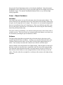
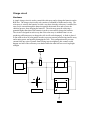
Implementation Notes
Solar Group
The Solar Array
Hardware
The solar array is made up of 42 panels each rated at 0.5V and 125mA in noon sunlight.
Each individual cell contains a solder strip on the top that is the negative terminal and
anywhere on the back of the panel is the positive terminal. The cells are soldered
together in a manner to get a voltage that is higher than the battery voltage at full charge
and to get the highest possible amount of current. This is done by wiring three sets of 14
cells in series. Then each one of these cells is solder together in parallel to produce a
theoretical 7V @ 375mA in full noon sun.
To stop current from flowing back into the solar cells and wasting energy, diodes were
placed on the positive terminal of each of the 3 series sets. The diodes that were used are
1N4003 diodes rated at 12V @ 1A maximum which is below the maximum output the
solar array can produce.
The cells are attached to a 6”x8” piece of perf-board using foam double sided tape. They
are arranged in six rows of seven to fit on the perf-board with little room to spare. All of
the spare wire is taped to the perf-board using electrical tape to prevent short circuits
The perf-board is attached to the robot using 3 long bolts. Two of the bolts are attached
to the back of the BoeBot through the predrilled holes. The third bolt is attached to the
front of the robot through a precut slot that was drilled out to accommodate the girth of
the bolt. Each bolt is attached to the BoeBot and perf-board using four washers and four
nuts with one set on each side of a surface.
Light Seeking
Hardware
The Photoresistors that were used to design the
light seeking work by varying their resistance
with the amount of light it senses. A high
resistance indicates very low light and a low
resistance indicates bright light. A simple RC
circuit is used to measure the resistance of the
photoresistors by measuring the time it takes a
capacitor to discharge through the
photoresistor to ground. Refer to the diagram
for a schematic of the RC circuit used.
To achieve our light seeking algorithm two
photoresistors were mounted on the front
corners of the perf-board using electrical tape.
These two photoresistors worked in
conjunction for navigational purposes. Also, one resistor was placed flat on the top of the
perf-board to measure the strength of the light shining directly down on the solar array to
indicate when the robot has reached an area with bright enough light.
To increase the sensitivity of the top photoresistors to bright light, the RC time constant
had to be adjusted to bring the final discharge time into the range of the Basic Stamps
RCTIME function. The formula to calculate the discharge time is based on a constant
times the values of R and C which are the resistance of the photoresistors and
capacitance. When in bright light the value of R will decrease dramatically causing the
resolution of the calculated discharge time to drop to the point of uselessness. To correct
this a 0.1µF capacitor was used on the top photoresistor instead of a 0.01µF capacitor like
the ones used on the navigational circuits.
Software
To seek light the code was written to store the values of all three photoresistors using the
Basic Stamp’s RCTIME function. Then a decision was made based on the value of the top
resistor. If the value was smaller than 60 then the robot goes into charge mode.
Otherwise the robot will seek out light by first calculating a deadband.
The deadband is a value that will
be used when comparing the
values of the left and right
photoresistors. If the difference
between the left and right
photoresistors is less then the
deadband then the robot will
navigate straight, which ultimately
means that the light source is
directly in front of it. To make the
robot navigate more smoothly, we
used a dynamic deadband that is
less sensitive in dark light and
more sensitive in bright light. This
is done by taking the square root of
the lowest value of the left and
right photoresistors then
multiplying it by five.
if abs(lt_photo-rt_photo) > deadband
then skip1
if if_object = 0 then skip_avoid
gosub avoid_obj
goto skip0
skip_avoid:
gosub straight
if moved then skip0
skip1:
if lt_photo < rt_photo then skip2
gosub right_turn
if moved then skip0
skip2:
if lt_photo > rt_photo then skip0
gosub left_turn
if moved then skip0
skip0:
moved = 0
If the difference between the resistors is not less then the deadband then the robot has to
turn toward the light. To do this a simple if…then statement compares the two values
and turns toward the direction of the lower of the two. It will continue turning until the
difference between the two resistors falls below the deadband. The figure above is
sample code taken from a loop in the program that loops until the top photoresistor is
indicating that light has been found.
Early tests when using a static deadband resulted in the robot shacking back and forth
when it was far from a light source. This is because it could not get the difference
between the left and right photoresistors to less then the deadband. Using the dynamic
deadband the robot is more likely to travel toward the light from far distances because the
deadband is larger. The dynamic deadband ultimately lead to a very sufficient light
seeking algorithm.
Sonar – Object Avoidance
Hardware
One simple sonar sensor was used for elementary object detection and avoidance. The
sensor consisted of one transmitter and receiver and connected to the Basic Stamp using
two pins, one for input and one for output. The sonar device was mounted using plastic
that was cut and bent to form an L-shaped piece. Holes were drilled to attach the sonar
device to the plastic, then that piece was attached to the robot using the front mounting
bolt of the perf-board/solar array.
The sonar works by transmitting a wave then measuring the time it takes for the echo to
reach the receiver. The wave travels at a constant speed so the distance to an object can
be calculated by dividing the perceived distance in half.
Software
The light seeking algorithm incorporated object detection into its decisions to call a
separate function for object avoidance. An object was considered detected if the value
calculated from the sonar sensor was less than 30 which relates approximately to 30
inches. Once an object was detected a function was called to avoid the object.
Object avoidance also incorporated a bit of light seeking. When an object is detected, a
decision is made on what direction to turn based on the direction of the strongest light.
The robot then turn in that direction until it no longer detects an object in front of it. It
then will turn a little further to create enough clearance for the solar array to clear the
object. Then the robot drives straight for a set distance then returns to the light seeking
algorithm.
Charge circuit
Hardware
A simple charge circuit is used to control the solar array and to charge the batteries on the
BOE-bot. The charge circuit really only consists of a handful of diodes and a relay. The
solar array is wired to the batteries in such a way that, when the solar array is enabled, the
array forces current through the batteries opposite the normal flow and reverses the
chemical process, thus charging the batteries. The solar array must be achieving a
potential higher than that of the batteries in order to successfully charge the batteries.
The circuit is designed in such a way that if the solar array is enabled when it is not
producing sufficient power to charge the cells it will not be damaged. A diode is placed
in line with each set of solar panels in order to prevent current from flowing into the array
and wasting power and possibly damaging the cells. This configuration also prevents
current from one series of panels from flowing into its neighbors; this scenario could
happen one half of the solar array was shaded while the other half was receiving bright
sunlight.
Software
The relay is controlled by I/O pin #6 and is wired so that it is normally off. We did this
in order to prevent overcharging (e.g. the robot is turned off and left out in the sun). The
downside of this is that the robot must be powered on to activate the solar array. In other
words, you must have batteries with at least a little power left in them to begin the
charging process.
Voltage monitor
Hardware
To measure the battery voltage the battery is used to
charge a capacitor through a resistor. The voltage is
then calculated from the charging time of the
capacitor using the Stamp's rctime command. I/O
pin #15 is used to charge the circuit and measure the
time to discharge. See the following circuit diagram.
Software
A simple stamp test program to measure the battery
voltage is as follows.
rct
vmeasured
C1
C2
con
con
var
var
word
word
' rctime value
' voltage value
52313 ' constant one
7
' constant two
low 15
rctime 15,0,rct
vmeasured = C1 / rct + C2
debug home, dec ? rct, dec ? vmeasured
debug "Vmeasured = ", dec vmeasured/10, "." ,dec1 vmeasured
This
program displays the raw rctime value and the calculated voltage. You will see that as
you increase the applied voltage the time to charge up the capacitor up decreases. Note
that we could have simply used the value returned by rctime to make decisions in the
code but it is more intuitive to work with an actual voltage value.
To convert the rctime value to a voltage value, constants C1 and C2 are calculated
empirically in the following manner. Measure the applied voltage at two points, V1 and
V2, and the corresponding raw values from the rctime command, T1 and T2. Having
these values, it is possible to linearly interpolate between the two in order to find an
approximate voltage for any given value returned by the rctime command.
V1: lower voltage applied to circuit
T1: corresponding raw rctime value
V2: higher voltage applied to circuit
T2: corresponding raw rctime value
C1 = 10 * (V1 - V2) * (T1 * T2) / (T2 - T1)
C2 = 10 * V1 - (C1 / T1)
The equation is an approximation but it works well because the charging curve is near
linear since the battery voltage is several times higher than the 1.3 volt threshold of the
BASIC stamp. Also, the battery voltage will be fairly constant around 5 to 7.2 volts for
our six volt battery pack. Note that you can't use a value of greater than 65535 for C1
due to the 16-bit limitations of the stamp.
USER’S MANUAL
Self Sustaining Solar Power Robot (SSSPR)
ASSEMBLY................................................................................................................... 1
Battery Installation (Step 1)........................................................................................ 1
Solar Array Attachment (Step 2)................................................................................. 1
Cable Connections (Step 3) ........................................................................................ 2
OPERATION ................................................................................................................ 2
TROUBLESHOOTING ............................................................................................... 2
ASSEMBLY
The following components are needed to assemble and operate the SSSPR:
• 1
Solar array (with on-board circuitry)
• 1
BOE-bot (with on-board circuitry)
• 1
Battery Charger (compatible with rechargeable AA alkaline 1.5 volt
batteries)
• 4
Rechargeable AA alkaline 1.5 volt battery
• 3
Nuts
• 6
Washers
NOTE:
It is recommended that steps be performed in the order presented in the
manual.
Battery Installation (Step 1)
The SSSPR is equipped to hold 4 AA 1.5volt alkaline batteries which come charged and
ready to use. They may be installed as follows:
1.
2.
place the body of the SSSPR upside down so that it rests on the three bolts
extending from the body
place the batteries as indicated on the battery compartment
CAUTION: Do not mix old batteries with new batteries or use batteries with varying
charge level when placing them in the SSSPR. Only use rechargeable AA
alkaline 1.5 volt batteries.
Solar Array Attachment (Step 2)
The solar array and BOE-bot are separated during transportation to prevent damage to the
solar array. The board may be attached to the SSSPR body by the following steps:
1.
2.
place three washers on the three bolts extending from the SSSPR body so that
it rests on the nuts
gently place solar array board so that it rests on the washers by aligning holes
on the board with bolts extending from the SSSPR
3.
NOTE:
4.
5.
if board is not level with the ground, make adjustments to the nuts underneath
so that the board is parallel to the ground
Make sure to leave clearance for circuitry on the body of the SSSPR and
enough bolt exposed above the board to place a washer and a nut.
place three washers on the three bolts extending through the solar array board
screw nuts onto bolts to secure the board onto the SSSPR
CAUTION: Solar array arrangement is fragile. If any of the solar cells look damaged,
do not use the array as this may prevent correct operation of the SSSPR.
Cable Connections (Step 3)
The SSSPR has two cable connections to be completed before operation. The
connections are to be made as follows:
1.
2.
the blue cable extending from the SSSPR body connects the right jack on the
solar array board (this jack is wired to the blue cable on the solar array board)
the white cable extending from the SSSPR body connects the right jack on the
solar array board (this jack is wired to the white cable on the solar array
board)
WARNING: Do not plug cables into the wrong jacks as this could cause serious
damage to the circuitry on both the SSSPR body and solar array board.
OPERATION
The SSSPR is self sustaining and should need no intervention from humans to operate
once it is turned on. Follow these steps to turn on the SSSPR:
1.
press the reset button on the SSSPR body (the black reset button is located on
the green board between the green LED and a wheel)
2.
with the reset button pressed, plug in the power cord coming from the battery
pack into the power insert located on the SSSPR body (the black power insert
is located on the green board next to the 9 volt battery connection)
3.
place the SSSPR on a clean floor and release the reset button
TROUBLESHOOTING
In order for the SSSPR to function properly, it must be initially started with a charged set
of batteries. If the robot does nothing after putting in the batteries, the batteries should be
charged by placing it in the charger.
Any damaged to the solar array, SSSPR body, or any circuitry can cause complete
failure. If any such damage is noticed or suspected, return the SSSPR.
Course Debriefing – Solar Group
Did your group management style work?
Our group management style worked very well. We did not assign official roles or
positions but rather decided as a team what needed to be done and then individually did
what was necessary to achieve our goals. During the course of the project it was
interesting to see each group member naturally settle into an efficient and effective team
role. This management style is very simplistic and most likely would not have worked if
we had more than three members on our team.
If you were to do the project again, what would you do the same, what
would you do differently?
One of the best things we did as a group was to setup regular weekly meeting times. We
would meet, at a minimum, twice a week. Having a minimum was good in that it ensured
we were communicating and that our project was on track. My only suggestion for doing
something different would be to limit the length of our meetings (even though this would
require us to meet more often). It seemed that our productivity started to really wane
after about four hours.
Are there any particular safety and/or ethical concerns with your
product(s)? What steps did your group take to ensure these
concerns were addressed? Are there any additional steps you would
have taken if you were to do the project again?
There really are not any particular ethical concerns with our robot. Perhaps there could
be a minor safety issue with the heat of the solar panels. But since they do not get hot
enough to burn a person we have not done anything to address this issue.
Did you test your product(s)? Do they work as advertised? Can you
think of any relevant situations in which you haven’t tested your
product(s)? If you were to do this project again, what additional
verification and testing procedures might you add?
We tested our robot to ensure that its light tracking and object avoidance worked properly
(both the sensors and the algorithms). We also tested our robot’s charge circuit to verify
that it was properly charging the batteries and that the voltage readout was functioning.
We have not tested our robot under a work light for an extended period of time; the robot
was designed to charge in sunlight and we are just using the work light for demonstration
purposes. The halogen bulb of the lamp heats the solar array to much higher
temperatures than leaving it outside in the sun and it is unclear whether or not this higher
temperature will adversely affect the performance of the solar panels. If we were to do
this project again we would certainly spend more time testing the object avoidance
behavior of the robot. While our robot performs object avoidance fairly well, we believe
it could be improved through further testing.