1
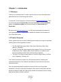
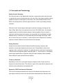
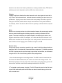
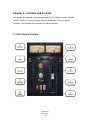
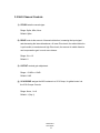
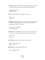
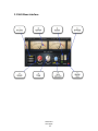
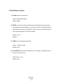
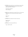
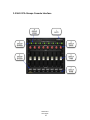
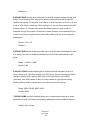
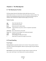
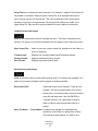
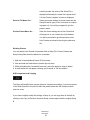
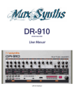
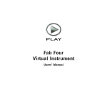
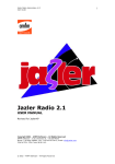
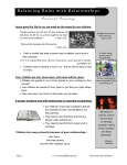
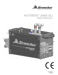
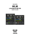
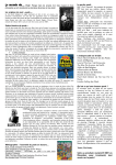
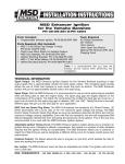
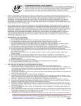
WAVES NLS NON-LINEAR SUMMER USER GUIDE Table of Contents Chapter 1 – Introduction..................................................................... 3 1.1 Welcome.................................................................................................................. 3 1.2 Product Overview .................................................................................................... 3 1.3 Concepts and Terminology...................................................................................... 4 1.4 Components ............................................................................................................ 7 Chapter 2 – Quick Start Guide ........................................................... 8 Chapter 3 – Interface and Controls .................................................. 10 3.1 NLS Channel Interface .......................................................................................... 10 3.2 NLS Channel Controls........................................................................................... 11 3.3 NLS Buss Interface................................................................................................ 13 3.4 NLS Buss Controls ................................................................................................ 14 3.5 NLS VCA Groups Console Interface ..................................................................... 16 3.6 NLS - VCA Group Console Controls ..................................................................... 17 Chapter 4 – The WaveSystem ......................................................... 20 4.1 The WaveSystem Toolbar ..................................................................................... 20 4.2 Preset Handling ..................................................................................................... 20 4.3 Interface Controls .................................................................................................. 23 4.4 Waves Preferences (Pro Tools only)..................................................................... 25 Waves NLS User Guide 2 Chapter 1 – Introduction 1.1 Welcome Thank you for choosing Waves! In order to get the most out of your Waves processor, please take the time to read through this manual. In conjunction, we also suggest you become familiar with www.wavesupport.net. There you will find an extensive Answer Base, the latest Tech Specs, detailed Installation guides, new Software Updates, and current information on Authorization and Registration. By signing up at www.wavesupport.net, you will receive personalized information on your registered products, reminders when updates are available, and information on your authorization status. 1.2 Product Overview Waves, together with three of today’s leading producer/engineers, brings you the analog summing sound of three legendary consoles The SSL 4000G belonging to Mark ‘Spike’ Stent (Radiohead, Björk, Muse, Maroon 5, Madonna). The EMI TG12345 Mk 4 desk owned by Mike Hedges (The Cure, Siouxsie and the Banshees, Dido, Faithless, Manic Street Preachers, U2), heard on such timeless recordings as Pink Floyd’s The Dark Side of the Moon. The Neve 5116 console custom-made for Yoad Nevo (Bryan Adams, Pet Shop Boys, Sugababes, Goldfrapp, Air). In all, Waves meticulously modeled over 100 individual channels, analyzing and emulating the distinctive color, character, and behavior of each and every input and summing bus amp. One of the great things about the digital environment is also one of its greatest drawbacks: Its linearity, while utterly transparent, often results in sterile tracks that lack warmth and harmonic depth. NLS delivers the richness and complexity that only analog gear has been able to provide—until now. Waves NLS User Guide 3 1.3 Concepts and Terminology Analog Console Summing Ever since the dawn of the digital audio revolution, engineers the world over have tried to replicate the sound of analog summing, in the box. Many top engineers add an analog hardware console or summing box to their setup, and route multitrack audio from the DAW to the analog device, and back again as stereo, in order to get analog summing coloration. With that in mind, Waves began exploring the mysteries of analog summing with the help of Mark ‘Spike’ Stent, who generously lent us his SSL 4000G desk. Our research suggested that its individual channel preamps, working together with one another in conjunction with the master buss preamp, are responsible for its indefinable yet highly desirable sound. Furthermore, we concluded that perceived depth and image—what we’ve come to know as ‘non-linearity’—are the result of minor differences in frequency response, harmonic distortion and noise between the channels. Analog Character Analog devices produce electrical artifacts that affect frequency response, add harmonics, cause signal clipping and increase noise. These artifacts, which sound engineers often consider the ‘character’ of a particular device, result from a combination of factors such as component grade, technology type (i.e., vacuum tubes vs. transistors), power supply specifications, equipment casing and other variables. Waves modeled these artifacts for each individual console channel. Frequency Response Depending on the circuit, input signal frequency response varies. Some circuits cut frequencies; others boost them. This behavior is part of the overall device character, and should not be confused with user-adjustable EQ. Harmonics (THD/Total Harmonic Distortion) THD is low-level distortion based on the levels of the odd and even harmonics of an input signal, usually at a level much lower than the fundamental level. Normally, each Waves NLS User Guide 4 harmonic is at a lower level than its predecessor, creating a natural decay. THD balance and decay are circuit dependent, and thus differ from device to device. Clipping Clipping is high-level distortion that adds harmonics to the input signal at a level that is very close to the fundamental level, with each harmonic remaining at a level close to its predecessor. Clipping occurs when a device such as a preamp is fed with a signal too strong for it to handle, and the device ‘chops’ the waveform to fit its power limitations. For example, when a sine wave is driven hot into a preamp, it almost becomes a square wave. Noise Noise occurs in analog devices due to the interaction between the power supply and the device’s electrical and magnetic shielding properties, resulting in random low level signals. The noise level defines the dynamic depth of the usable signal, what we call Signal-to-Noise Ratio or SNR. For example, in a 16-bit audio file, the noise level is -95 dBFS, which translates into 95 dB of depth. In an analog console, where noise is set at about -80 dBu and the clipping point is 20 dBu, the depth is 100 dB. Session Setup Since analog console coloration is created by the console’s individual channel and buss amplifiers, the NLS includes both Channel and Buss components. To faithfully reproduce the DAW to analog console (and back again) signal chain and workflow, we recommend using the NLS in one of two following session setup configurations. 1. As a virtual summing box or summing console: The NLS Channel is inserted on the last insert of the DAW audio tracks, like a direct out routed to an analog console. The NLS Buss is placed on the first insert of the master track (or any other buss), just as the stereo return would be routed from the analog console back to the DAW. 2. To simulate console preamp coloration: The NLS Channel is placed on the first insert of your DAW audio tracks, and the NLS Buss can then be inserted at any point on the buss or master track. Waves NLS User Guide 5 The NLS automatically ensures channel variation by loading a different channel model for each instance of the NLS Channel component, chosen from the pool of 32 modeled channels per console. VCA Groups In the analog world, VCA is an acronym for Voltage Controlled Amplifier. On many analog consoles, there is a physical distance between channels that makes it difficult to move them simultaneously. Therefore, many consoles are equipped with VCA group faders which are used to control the output amplifiers of multiple channels. In the NLS plugin, VCA stands for Virtual Control Aggregator which, similar to its analog counterpart, provides simultaneous control over multiple NLS Channel instances. For easy access, the NLS VCA Groups Console can be opened from any NLS instance. Each NLS instance must be assigned, from within its GUI, to a VCA Group. Please note: VCA Group Consoles do not process your signal in any way; rather, they serve as remote control surfaces for groups of NLS instances. Presets There are 32 channels and master buss presets per Studio console. User presets are comprised of two parts: one for the Channel or Buss section, and one for the VCA Groups Console section. Each section may be loaded independently using the Waves preset system; they may not be loaded independently using your host’s preset system. NLS Channel components open different modeled presets for each instance. However, if a channel instance is duplicated, the same model will be duplicated as well. Therefore, we recommend that each NLS Channel instance is opened directly from your DAW dropdown menu, or using the shortcuts described below. Please note: When loading a Waves preset file, the first preset inside the file will not be loaded automatically; it must be loaded manually from the Load menu. Waves NLS User Guide 6 1.4 Components WaveShell technology enables us to split Waves processors into smaller plugins, which we call components. Having a choice of components for a particular processor gives you the flexibility to choose the configuration best suited to your material. Waves NLS includes two components each in two channel configurations: NLS Channel Mono NLS Channel Stereo NLS Buss Mono NLS Buss Stereo All NLS components have IRXUVDPSOHVRI latency. Waves NLS User Guide 7 Chapter 2 – Quick Start Guide As a starting point, we recommend using the NLS in one of the two configurations described above. Quick Start Open the NLS Channel at the last insert point on every track. Open the NLS Buss on your master or other buss. VCA Group Usage By default, all NLS instances are assigned to VCA Group 1. For global control over all NLS instances in the session, open the VCA Group Console via one of the Channel or Buss instances. Set the VCA Group Drive which affects all instances in the group. Set the VCA Group Trim, if required. Select the VCA Group Studio setting. Selecting INDIV leaves each NLS instance with its selected Studio setting; selecting SPIKE, MIKE or NEVO changes all NLS instances in the group to the selected Studio. Set the VCA Group Noise, if required. Advanced VCA Group Usage Set all NLS Channel instances on drum tracks (for example) to VCA 1. Set all NLS Channel instances on guitar tracks (for example) to VCA 2. Set all NLS Channel instances on vocal tracks (for example) to VCA 3, and so on. Set all NLS Buss instances to VCA 8. Open the VCA Groups Console. Using the VCA Tab, rename the groups according to their assignments by double-clicking on the text field, typing the new name, and clicking Enter: Grp1 renamed to Drums (for example), Grp 2 renamed to Guitars (for example), etc. Open the VCA Groups Console in the Master track NLS instance, and turn on Auto, enabling VCA write/read automation. Use the VCA Groups Console as your main stem control. Waves NLS User Guide 8 Host-Specific Shortcuts Pro Tools To create multiple plugin instances for the entire session: Hold Alt/Option + select NLS on a Mono track. Hold Alt/Option + select NLS on a Stereo track*. To create multiple plugin instances for selected tracks Select multiple channels. Hold Shift + Alt/Option + select NLS on a Mono track. Hold Shift + Alt/Option + select NLS on a Stereo track*. *This is to ensure that Stereo tracks receive NLS stereo components rather than two NLS mono components (multi-mono). Setting NLS VCA Groups for Grouped Tracks Create Pro Tools Edit/Mix groups. In the Group menu, select Modify Groups, open the Globals tab, and check the Control box next to the Insert point (a or j) where NLS will be instantiated. Instantiate NLS for the Pro Tools group. Open one NLS instance and assign the NLS VCA group; this selection will be duplicated to all NLS instances in the Pro Tools group. Cubase / Nuendo To create multiple plugin instances for selected tracks: Select multiple channels. Hold Alt/Option + Shift and insert NLS on the first channel. Logic To create multiple plugin instances for selected tracks: Select multiple channels. Insert NLS on one of the Mono tracks in the selection. Insert NLS on one of the Stereo tracks in the selection. Waves NLS User Guide 9 Chapter 3 – Interface and Controls NLS graphic user interface comprises three elements, the Channel controls, the Buss controls, and the VCA Group Console section available as a Tab in the Channel instances or as a foldable GUI extension in the Buss instances. 3.1 NLS Channel Interface Waves NLS User Guide 10 3.2 NLS Channel Controls 1) STUDIO sets the console type. Range: Spike, Mike, Nevo Default: Spike 2) DRIVE controls the amount of harmonic distortion, increasing the input signal and decreasing the internal headroom. At lower Drive levels, the added distortion is quite subtle; at moderate and high Drive levels, the amount of added distortion and compensation gain is much more intense. Range: 0 to +12 Default: 0 3) OUTPUT controls gain adjustment. Range: -12 dB to +12 dB Default: 0 dB 4) VCA GROUP assigns the NLS instance to a VCA Group, for global control via the VCA Groups Console. Range: None, 1 to 8 Default: 1 (Grp 1) Waves NLS User Guide 11 5) LINK toggles between Dual Mono mode, where the left and right channels are not identical models, and Stereo mode, where left and right are identical. Range: Dual Mono, Stereo Default: Dual Mono 6) MIC changes the headroom by simulating mic input levels. Range: On, Off Default: Off 7) BYPASS deactivates analog harmonics, noise and frequency response effects. Please note: The Bypass setting of the VCA Group Console overrides the Bypass settings of specific NLS instances. Range: Bypass, Not Bypassed Default: Not Bypassed 8) NOISE activates modeled analog noise. Please note: The noise setting of the VCA Group Console overrides the Noise settings of specific NLS instances. Range: On, Off Default: On 9) VCA TAB shows and hides the VCA Groups Console section. Range: VCA Tab, Channel Tab Default: Channel Tab 10) METER displays output signal peak dBFS values. Range: -24 dBFS to 0 dBFS Waves NLS User Guide 12 3.3 NLS Buss Interface Waves NLS User Guide 13 3.4 NLS Buss Controls 1) STUDIO sets the console type. Range: SPIKE, MIKE, NEVO Default: SPIKE 2) DRIVE controls the harmonic distortion ratio, increasing the input signal and decreasing the internal headroom. At lower Drive levels, the added distortion is quite subtle; at moderate and high Drive levels, the amount of added distortion and compensation gain is much more intense. Range: 0 to +12 Default: 0 3) TRIM controls output gain adjustment. Range: -12 dB to +12 dB Default: 0 dB 4) VCA GROUP assigns the NLS instance to a VCA Group, for global control via the VCA Groups Console. Range: None, 1 to 8 Default: None Waves NLS User Guide 14 5) BYPASS deactivates analog harmonics, noise and frequency response effects. Please note: The Bypass setting of the VCA Group Console overrides the Bypass settings of specific NLS instances. Range: Bypass, Not Bypassed Default: Not Bypassed 6) NOISE activates modeled analog noise modeling. Please note: The noise setting of the VCA Group Console overrides the Noise settings of specific NLS instances. Range: On, Off Default: On 7) SHOW VCA shows and hides the VCA Groups Console section. Range: Show, Hide Default: Show 8) METER displays output signal peak dBFS values. Range: -24 dBFS to 0 dBFS Waves NLS User Guide 15 3.5 NLS VCA Groups Console Interface Waves NLS User Guide 16 3.6 NLS - VCA Group Console Controls VCA Group Console settings are the same in all NLS instances across the session. VCA Group Controls do not support Undo/Redo functions. VCA Group Console settings are the same for plugin Setups A and B. VCA Group Console settings can be loaded independently from the Waves preset system. To bounce tracks when VCA Group Console controls have been automated, use your audio host’s “real-time” bounce function. 1) AUTO enables automation writing and reading for the VCA Groups Console. To change the NLS instance used as your VCA Group automation master, disable AUTO on the currently enabled instance, and enable AUTO on a different instance. Please note: Automation writing may only be activated from the AUTO-enabled instance; only one instance can be AUTO-enabled per session. Only the AUTO-enabled instance can be controlled using an external control surface. Range: On, Off Default: Off 2) GROUP BYPASS deactivates the NLS effect on all instances assigned to that VCA Group. Please note: The VCA Group Console Bypass setting overrides the Bypass settings of specific NLS instances. Range: Bypass, Not Bypassed Default: Not Bypassed 3) GROUP NOISE controls the noise for all the NLS instances assigned to that VCA Group. Please note: The Noise setting of the VCA Group Console overrides the Noise settings of specific NLS instances. Range: On, Off Waves NLS User Guide 17 Default: On 4) GROUP DRIVE sets the drive offset value for all NLS instances assigned to that VCA Group. The VCA Group Drive value will be added or deducted from that of each NLS instance in the group. For example, if an instance of NLS Channel is set to Drive +8, and is part of VCA Group 2 which has a Drive setting of +5, the total Drive value for that NLS Channel will be +13. At lower Drive levels, the added distortion is quite subtle; at moderate and high Drive levels, the amount of added distortion and compensation gain is much more intense. Negative Drive values affect THD levels, but do not change the makeup gain. Range: - 12 to +12 Default: 0 5) GROUP TRIM sets the output gain offset value for all NLS instances assigned to that VCA Group. This value is added or subtracted from that of each NLS instance in the group. Range: -12 dB to +12 dB Default: 0 dB 6) GROUP STUDIO sets the studio type for all NLS instances assigned to that VCA Group. Please note: The Studio setting of the VCA Group Console overrides the Studio settings of specific NLS instances. When the VCA Group Studio is set to INDIV (Individual), each NLS instance in the VCA Group retains its original Studio setting, allowing different Studio consoles to be used within the same VCA Group. Range: INDIV, SPIKE, MIKE, NEVO Default: INDIV 7) GROUP NAME is a text field which allows you to customize the name (up to seven characters) of each VCA Group, automatically updating the name in all NLS instances. Default: Grp1 to Grp8 Waves NLS User Guide 18 Waves NLS User Guide 19 Chapter 4 – The WaveSystem 4.1 The WaveSystem Toolbar All Waves plugins feature the WaveSystem toolbar which takes care of most administrative functions you will encounter while working with your Waves software. The features of the WaveSystem toolbar are the same on practically all Waves plugins, so familiarity with its features will be helpful whichever plugin you are using. Toolbar Functions Opens the plugin About box Undo Undoes the last 32 actions Redo Redoes the last 32 undone actions Setup A/B Toggles between two presets, useful for comparison of parameter settings L/R Arrows Move to the previous or next preset Copy A→B Copies the current settings to the second preset register Load Recalls presets from file Save Saves presets in the Waves file formats ? Opens the PDF manual for the plugin you are using 4.2 Preset Handling Preset Types Factory Presets are permanent presets in the Load menu. Factory presets cannot be overwritten or deleted. When applicable, different component plugins may have different factory presets. User Presets are your favorite settings of the plugin saved as a preset in the Load menu, under ‘User Presets’. User Presets can be overwritten and deleted. Waves NLS User Guide 20 Setup Files may contain more than one preset. For example, a single file can contain all the presets for a session. When you open a Setup File, all its setups become part of your Load pop-up menu for fast access. This can be particularly useful with multiple instances of a plugin in a single session. By saving all the settings you create into a single Setup File, they can all be quickly available for every instance of that plugin. Loading Presets and Setups Click on the Load button to see the Load pop-up menu. The menu is divided into four sections. If a section is not currently available it will not appear in the Load pop-up menu. Open Preset File… Select to open any setup or preset file, whether from the Library or your own creations. ‘Filename.xps’: Displays any currently loaded Setup File and its presets. Factory Presets: Displays the default Factory Presets. User Presets: Displays any loaded User Presets. Saving Presets and Setups Click on the Save button to see the Save pop-up menu. Four options are available. If an option is not currently available it will be grayed out and inaccessible. Save to New File… Select this to start a new Setup file. There are two prompts - first for the setup filename, then for the preset name. You must provide a name for both the setup file and the preset. Click OK (ENTER) to complete the save. It is a good idea to create a folder in which to save several setup files for a project. Save ‘File Name’ – “Preset Name” Overwrites the settings of the loaded preset (whether a User Preset or a preset from a Setup File) with the current settings. If a Setup File is Waves NLS User Guide 21 currently loaded, the name of the Setup File is displayed followed by the name of the preset itself. If a User Preset is loaded, its name is displayed. Save to ‘File Name’ As… Saves the current settings as a new preset into the Setup file that is open (if one is not open, the option is grayed out). You will be prompted to give the preset a name. Put into Preset Menu As… Save the current settings into a User Preset that will always be in your Load menu (until deleted). You will be prompted to give this preset a name. User Presets are stored in the plugin’s preference file. Deleting Presets You may delete User Presets and presets within a Setup File. Factory Presets and Setup Library files cannot be deleted or overwritten. 1. Hold the Command (Mac)/Control (PC) key down. 2. Click-and-hold the Load button to see the pop-up menu. 3. While still holding the Command/Control key, select the preset or setup to delete. 4. A confirmation box will appear, allowing you to cancel or ‘OK’ the deletion. A/B Comparison and Copying The Setup A/Setup B button may be clicked to compare two settings. If you load a preset in the Setup B position, this will not affect the preset loaded into the Setup A position, and vice-versa. If you want to slightly modify the settings in Setup A, you can copy them to Setup B by clicking on the Copy to B button, then alter Setup A and compare with the original Setup B. Waves NLS User Guide 22 The name of the current setup will be shown in the title bar (on platforms which support it), and will switch as you change from Setup A to Setup B. Note: an asterisk will be added to the preset name when a change is made to the preset. 4.3 Interface Controls Controls can be in one of three states: 1. Not Selected where the control is not the target of any user entry 2. Selected where the control is the target of mouse control entry only 3. Selected and Active where the control is the target for both mouse and keyboard entry Toggle Buttons Toggle buttons display the state of a control, and allow switching between two or more states. Single-click to change the control’s state. Some toggle buttons have a text display which updates with the current setting, and others (bypass, solo, or monitoring toggles) illuminate when the control is active. Some plugins have link buttons between a pair of toggle buttons, allowing click-anddrag adjustment while retaining the offset between the controls. Value Window Buttons Value windows display the value of a control and allow click-and-drag adjustment, or direct control via the keyboard. Using the mouse, click-and-drag on the value window to adjust. Some value windows support left/right, some up/down (as you hover over a button, arrows will appear to let you know which direction of movement that button supports). You may also use your mouse-wheel to adjust parameter values. Using the arrow keys, click once with mouse to select the button, and then use up/down – left/right (depending on the direction supported by that button) to Waves NLS User Guide 23 move in the smallest incremental steps across the button’s range (holding down the arrow keys will move faster through the range). Using key entry, double click on the button to open the value window, and directly enter the value from your keyboard. If you enter an out of range number, the button stays selected but remains at the current setting. (System beeps if system sounds are on.) Some plugins have link buttons between a pair of value windows, allowing click-anddrag adjustment while retaining the offset between the controls. Sliders Click or scroll the mouse-wheel on the slider itself or anywhere within the sliders track. The numerical value of the slider settings is displayed in a hover window above the slider path. Hover Box Hovering boxes will appear and display the control value when hovering with the mouse over the control. Multiple Control Selection One of the most powerful features of the WaveSystem is the ability to select and adjust multiple controls simultaneously. Using the mouse, drag-select the desired group of buttons or graphic controls by clicking and holding at a point outside the controls, and forming a rectangle that includes the controls you wish to adjust. Alternatively, press and hold Shift while clicking the mouse on any control you wish to link. This method is useful when you want to select two or more controls that are not adjacent to one another. Waves NLS User Guide 24 TAB Functions TAB moves the ‘selected’ status to the next control, with shift-TAB moving in the reverse direction. Additionally, the Mac has an option-TAB function for ‘down’ movement and shift-optionTAB for ‘up’ movement where applicable. If you have several Value Window Buttons selected, TAB functions will take you through the selected controls only. Hitting Esc or Return will return the 'focus' to the DAW application. 4.4 Waves Preferences (Pro Tools only) When launching Pro Tools, hold Shift to view the Waves plugin Preferences window. The following options are available: Don't use AudioSuite plugins Don’t use RTAS plugins Rescan all plugins HUI control surface support (low resolution) Enable single-click text entry Waves NLS User Guide 25