1
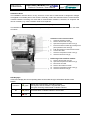
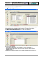
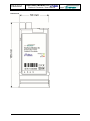
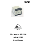
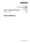
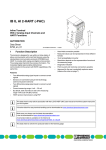
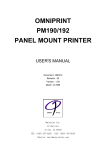
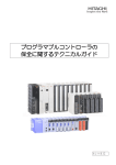
Interface Module XC Protocol Converter / User Manual Page 1 from 12 E130005815092 Bär Industrie-Elektronik GmbH Rathsbergstr. 23 D-90411 Nürnberg Phone +49 911 970590 Fax +49 911 9705950 General The Interface Module XC is designed for use with the EMH LZQJ-XC and DMTZ-XC meters. The module is equipped with a M-Bus (2 wires) interface. The module can be plugged easily into the module compartment of the meter. It can be mounted or exchanged during operation (without breaking approval seal). An integrated M-Bus interface (Protocol Converter to DIN EN 13757-3) provides a simple means of connecting multi-energy meters. This makes multi-energy applications an affordable proposition for domestic use. Due to the communication, the modules are suitable for a lot of control centres. Compatible meters LZQJ-XC (special meter for industrial applications): - Standard meter for direct connection - Transformer connection version Cl. B (Cl. 1) - Precision meter Cl. C (Cl. 0.5S) - Precision meter Cl. 0,2S DMTZ-XC (residential meter) Functions M-Bus interface (2 wires, passive) for bi-directional communications; Alternative: BFC-Bus (BAER Field Control, 56VDC); Transmission protocol: M-Bus (DIN EN 13757-3:2013-08); Internal communication interface for the transfer data between the meter and the interface module (service data list / table TS); Protocol converter for meter data into M-Bus-Format (non transparent data readout); Internal power supply from meter; Exchangeable during the meter operation; Safety Notes The owner of the interface modules is responsible that all persons engaged on work with the modules: • Are competent and qualified in accordance with national regulations (see ISSA "Guideline for Assessing the Competence of Electrically Skilled Persons"). • Have read and understood the relevant sections of the user manual. • Strictly observe the safety regulations (according to the following section) and the instructions in the individual chapters. The owner of the modules is also responsible for: • The protection of persons. • The prevention of material damage. • The training of personnel. The following safety regulations must be observed at all times: • Devices which have fallen down should not be installed, even if no damage is apparent, and should be returned for testing to an authorised service centre (internal damage possible). • Modules must never be cleaned with running water or high pressure devices. Water can cause short-circuits or damage el. components. Page 2 from 12 E130005815092 Interface Module XC Protocol Converter / User Manual Bär Industrie-Elektronik GmbH Rathsbergstr. 23 D-90411 Nürnberg Phone +49 911 970590 Fax +49 911 9705950 Installation Hints The installation must be done in a way, that even in the case of cable break no dangerous voltages are applied to touchable parts of the module. Generally, meters are delivered with the communication modules installed. The fitting of a meter with a communication module is, therefore, an exception and can be necessary e.g. when a module needs to be replaced. Strictly observe the safety regulations! The interface module is exchangeable during the meter operation. Fit the interface module in the meter as follows: Installation of the interface module: 1. Check the interface module. 2. Remove the terminal cover [5]. 3. Open the transparent module cover [1]. 4. Insert the interface module [3] carefully at the place provided in the meter [2]. 5. Push the module in to the internal contacts. 6. Connect the cable. 7. Close the transparent module cover [1]. 8. Close the terminal cover [5]. Removing of the interface module: 9. 10. 11. 12. 13. 14. Remove the terminal cover [5]. Open the transparent module cover [1]. Disconnect the cable. Remove the interface module. Close the transparent module cover [1]. Close the terminal cover [5]. LED Displays Three LED’s display the current operating status of the module and give information about the data transfer. Power/Tx green Status and communication via M-Bus interface: LED signals, that the module is supplied with power LED goes off during transmit data via M-Bus interface Rx yellow Communication via M-Bus interface: receive data red Communication error (internal meter interface) Error Interface Module XC Protocol Converter / User Manual Page 3 from 12 E130005815092 Bär Industrie-Elektronik GmbH Rathsbergstr. 23 D-90411 Nürnberg Phone +49 911 970590 Fax +49 911 9705950 Communication (M-Bus, Protocol Converter) The M-Bus interface is conforming to DIN EN 13757-3:2013-08. nd Fixed baud rate from the 2 electrical interface (see EMH COMBI-TOOL-Software: communication interfaces, set please the data transmission at a fixed baud rate without baud rate changeover), data format: 8E1; Parameterisation of the meter (EMH COMBI-TOOL-Software) At the first read the read all data from the meter (via optical IR interface): Baud rate The Interface Module XC uses the same baud rate like the communication interface at the meter. For setting use please the EMH COMBI-TOOL-Software: menu Meter Interfaces Electrical interface: For correct working set please a fixed bad rate (e.g. 9600 baud). If you use the baud rate changeover according to mode C: the communication is possible with 300 baud only. Reset Note: The EMH LZQJ-XC meter performs automatically a daily reset at 00:00 in the interface module. Page 4 from 12 E130005815092 Interface Module XC Protocol Converter / User Manual Bär Industrie-Elektronik GmbH Rathsbergstr. 23 D-90411 Nürnberg Phone +49 911 970590 Fax +49 911 9705950 Service Data List / Table TS and M-Bus-Address For setting the meter data list use menu Lists Reading lists Service Table TS: Note 1: the M-Bus module uses for ID-Addresses the OBIS Register 0.0.0 (secondary address) and 0.0.1 (primary address) in the service data list (TS). In this example we use the identification number 1 (OBIS 0.0.1) for M-Bus primary address: menu Meter Meter ID OBIS Register 0.0.1, e.g. value 123 (:= 00000123): Standards for M-Bus addresses: Primary address: OBIS Register 0.0.1 (Identification 1), range 1 to 250, default := 1 Secondary address: OBIS Register 0.0.0 (device number / fabrication number), range 0 to 99999999, default := 0 For determining the address it is possible to use the wildcard searching procedure (answer E5Hex). Interface Module XC Protocol Converter / User Manual Page 5 from 12 E130005815092 Bär Industrie-Elektronik GmbH Rathsbergstr. 23 D-90411 Nürnberg Phone +49 911 970590 Fax +49 911 9705950 Accepting the meter data The Interface Module XC reads the service data list / table (TS) from the meter periodically (interval between two readings: ca. 1 second) and creates an internal table. The OBIS coded values from the meter will be convert to the M-Bus data (DIFs/VIFs: according to DIN EN 13757-3:2013-08 without manufacturer specific extensions). Data field coding: 32 Bit Integer only (data field := 0100Binary), type B. Telegram format: variable data respond. Used telegram formats (examples): Master: SND_NKE (Send Link Reset) Answer: E5Hex (acknowledge) Master: SND_UD (CI-Field 52Hex for selection the secondary address; request via address FDHex) Answer: E5Hex (acknowledge) Master: REQ_UD2 (Request User Data Class 2) Answer: RSP_UD (Respond User Data) Further specifications: The following definitions shall also apply for the selection of a new secondary address (SND_UD): - the manufacturer code (15Hex A8Hex for “EMH”) will be evaluated, wildcard (FFHex FFHex) is possible; - the version byte (Ver) will be ignored: all bytes are possible (e.g.: FFHex); - the medium byte (02 for electricity) will be evaluated, wildcard (FFHex) is possible; Data encryption is not allowed. Max. telegram length: 252 bytes (ca. 30 values). Support only for mode 1 (CI-Field): the least significant byte (LSB) of a multibyte record is transmitted first. Status byte: only bit 4 (“temporary error”) is used: internal communication error between the modules and the meter. Implementation of one FCB-Bit (Frame Count Bit) only (use either the primary or secondary address). Page 6 from 12 E130005815092 Interface Module XC Protocol Converter / User Manual Bär Industrie-Elektronik GmbH Rathsbergstr. 23 D-90411 Nürnberg Phone +49 911 970590 Fax +49 911 9705950 Structure of a data telegram (RSP_UD) Name No. of Bytes Value (hex) Start L L Start C A CI Identification no. Manufacturer code Version of device Medium 1 1 1 1 1 1 1 4 2 1 1 68 LL LL 68 08 PAdr 72 SAdr 15 A8 Ver 02 Access No. 1 AccNo Status Signature User data 1 2 n Stat 00 00 ... Check sum Stop 1 1 xx 16 Description Length of the telegram Length of the telegram Control field: RSP_UD Primary address (OBIS-Register 0.0.1) Control information field: variable data respond Secondary address (OBIS-Register 0.0.0) Code for “EMH” Version of the interface module Electricity Access number is increased by one after each respond user data (RSP_UD) from the slave Status Not used Arithmetical sum of the data mentioned above User data Used OBIS-Registers: Counter values for active, reactive and apparent energy (OBIS-Registers 1.8.x, 2.8.x, 3.8.x, 4.8.x, 9.8.x, 10.8.x). Instantaneous values for active and reactive power, voltage, current and line frequency (OBISRegisters 1.25 at seq., 3.25 at seq., 12.25 at seq., 11.25 at seq. and 14.25). Possible OBIS-Registers in the service data list / table TS: OBIS-Register Description 0.0.0 Identification 0 (device address / meter number): secondary address 0.0.1 Identification 1: primary address; possible range: 1 to 250 1.8.t * s Counter value active energy, import 2.8.t * s Counter value active energy, export 3.8.t * s Counter value reactive energy, import 4.8.t * s Counter value reactive energy, export 9.8.t * s Counter value apparent energy, import 10.8.t * s Counter value apparent energy, export t = tariff (0..8), v = stored values (0..99) 1.25 Instantaneous value active power, cumulative 21.25 Instantaneous value active power, phase 1 41.25 Instantaneous value active power, phase 2 61.25 Instantaneous value active power, phase 3 3.25 Instantaneous value reactive power, cumulative Interface Module XC Page 7 from 12 E130005815092 Protocol Converter / User Manual Bär Industrie-Elektronik GmbH Rathsbergstr. 23 D-90411 Nürnberg Phone +49 911 970590 Fax +49 911 9705950 23.25 Instantaneous value reactive power, phase 1 43.25 Instantaneous value reactive power, phase 2 63.25 Instantaneous value reactive power, phase 3 12.25 Instantaneous value voltage, cumulative 32.25 Instantaneous value voltage, phase 1 52.25 Instantaneous value voltage, phase 2 72.25 Instantaneous value voltage, phase 3 11.25 Instantaneous value current, cumulative 31.25 Instantaneous value current, phase 1 51.25 Instantaneous value current, phase 2 71.25 Instantaneous value current, phase 3 14.25 Instantaneous value line frequency Other OBIS-Registers will not be stored and cannot be transmitted. Examples for read out with primary address: Master: 10 40 00 40 16 (primary address: 0 / SND_NKE: Send Link Reset) Answer: E5 Master: 10 40 FE 3E 16 (primary address: wildcard 254 = FEHex) Answer: E5 Master: 10 40 7B BB 16 (primary address: 123 = 7BHex) Answer: E5 Master: 10 7B 7B F6 16 (REQ_UD2: Request User Data) Answer: 68 0F 0F 68 08 7B 72 87 98 16 04 A8 15 00 02 00 10 00 00 FD 16 (empty message) Master: 10 5B Answer: 68 EA 00 00 84 20 05 FB 01 00 0C 00 03 0C 94 FC 00 00 FC 01 00 04 7B EA C4 03 82 00 00 00 02 04 3E FB D6 68 05 06 73 84 00 00 00 FD 00 2D 16 (REQ_UD2: Request User Data) 08 7B 72 87 98 16 04 A8 15 00 02 01 00 00 03 6D 13 00 00 84 10 03 C2 10 00 00 C4 15 06 00 00 C4 25 03 C5 04 00 00 04 FB 82 73 06 02 00 00 84 10 FB 82 73 4A 02 00 00 C4 20 FB 82 73 46 01 00 00 C4 25 FB 82 73 B1 04 AB FC 01 00 00 00 00 04 AB FC 02 00 00 00 04 FB 14 05 00 00 00 04 FB 94 FC 01 00 00 00 00 04 FB 94 FC 03 05 00 00 00 04 FD D8 FC 02 0E 00 00 00 04 FD D8 FC 03 13 03 00 00 04 FD C7 FC 02 38 00 00 00 04 FD C7 87 13 00 00 0C 16 (RSP_UD: Respond User Data) 00 03 90 15 00 00 00 D8 00 FC 04 A8 03 FB 00 00 00 FC 00 03 03 0E 00 82 00 04 00 01 04 30 C9 00 00 73 04 AB 04 10 FD 59 16 00 C4 54 2B FC FB 00 C7 00 Interface Module XC Page 8 from 12 E130005815092 Protocol Converter / User Manual Bär Industrie-Elektronik GmbH Rathsbergstr. 23 D-90411 Nürnberg Phone +49 911 970590 Fax +49 911 9705950 Examples for read out with secondary address: Master: 68 0B 0B 68 53 FD 52 00 00 00 00 FF FF FF FF 9E 16 (selection with the secondary address: 00 00 00 00) Answer: E5 Master: 68 0B 0B 68 53 FD 52 FF FF FF FF FF FF FF FF 9A 16 (selection with the secondary address: wildcard FF FF FF FFHex) Answer: E5 Master: 68 0B 0B 68 53 FD 52 87 98 16 04 FF FF FF FF D7 16 (selection with the secondary address: 04 16 98 87Hex) Answer: E5 Master: 10 7B Answer: 68 EA 00 00 84 20 05 FB 01 00 0C 00 03 0C 94 FC 00 00 FC 01 00 04 FD EA C4 03 82 00 00 00 02 04 3F FB 78 68 05 90 73 84 00 00 00 FD 00 2D 16 (REQ_UD2: Request User Data) 08 7B 72 87 98 16 04 A8 15 00 02 02 00 00 03 6D 13 00 00 84 10 03 E6 0F 00 00 C4 15 05 00 00 C4 25 03 C5 04 00 00 04 FB 82 73 06 02 00 00 84 10 FB 82 73 E5 01 00 00 C4 20 FB 82 73 0F 01 00 00 C4 25 FB 82 73 B1 04 AB FC 01 00 00 00 00 04 AB FC 02 00 00 00 04 FB 14 05 00 00 00 04 FB 94 FC 01 00 00 00 00 04 FB 94 FC 03 05 00 00 00 04 FD D8 FC 02 08 00 00 00 04 FD D8 FC 03 08 03 00 00 04 FD C7 FC 02 38 00 00 00 04 FD C7 87 13 00 00 32 16 (RSP_UD: Respond User Data) Master: 10 40 FD 3D 16 (deselection of the secondary address allocation) Answer: E5 00 03 F5 15 00 00 00 D8 00 FC 04 A8 02 FB 00 00 00 FC 00 03 03 0E 00 82 00 04 00 01 04 49 77 00 00 73 04 AB 04 0C FD 59 15 00 C4 54 2B FC FB 00 C7 00 Interface Module XC Protocol Converter / User Manual Page 9 from 12 E130005815092 Bär Industrie-Elektronik GmbH Rathsbergstr. 23 D-90411 Nürnberg Phone +49 911 970590 Fax +49 911 9705950 Technical data Housing: Polycarbonate housing with terminals for using with EMH LZQJ-XC and DMTZ-XC meters for residential and industrial applications Degree of protection: IP20 (according to IEC 60529) Protection class: 2 Temperature range: -25°C to +55°C (operational) -40°C to +80°C (storage temperature) Relative humanity: 0..95%, non-condensing Dimensions: Ca. 50mm x 105mm x 27mm (W x H x D) Nominal voltage: Internal power supply from LZQJ-XC or DMTZ-XC meter M-Bus load: 1,9mA, max. voltage: 56VDC Battery: None Installation: Exchangeable during the meter operation LED displays: 3 LEDs: (green) (yellow) (red) Power/Tx: power / transmit data via M-Bus Rx: receive data via M-Bus Error: internal communication error Interface: M-Bus (2 wires, passive) according to DIN EN 13757-2 (Physical Layer)Alternative: BFC-Bus (BAER Field Control, 56VDC) Baud rate: 300 to 9600 baud (fixed baud rate) Data format: 8E1 Data readout: Internal service data list / table TS Transmission protocol: According to DIN EN 13757-3:2013-08 (Application Layer) Order number: #12760 Accessories: Bus Master / Repeater / Mini-Master AMR-Software: SIGLON © Field Control Center: Meter2SCADA © Page 10 from 12 E130005815092 Interface Module XC Protocol Converter / User Manual Bär Industrie-Elektronik GmbH Rathsbergstr. 23 D-90411 Nürnberg Phone +49 911 970590 Fax +49 911 9705950 Dimensions Interface Module XC Protocol Converter / User Manual Page 11 from 12 E130005815092 Bär Industrie-Elektronik GmbH Rathsbergstr. 23 D-90411 Nürnberg Phone +49 911 970590 Fax +49 911 9705950 Terminal assignment Terminal block: Terminal Description a M-Bus (passive) or BFC-Bus b M-Bus (passive) or BFC-Bus Page 12 from 12 E130005815092 Interface Module XC Protocol Converter / User Manual Bär Industrie-Elektronik GmbH Rathsbergstr. 23 D-90411 Nürnberg Phone +49 911 970590 Fax +49 911 9705950 Baer Industrie-Elektronik GmbH Rathsbergstr. 23 D-90411 Nürnberg Phone: +49 (0)911 970590 Fax: +49 (0)911 9705950 Internet: www.baer-gmbh.com Subject to change without notice! Version 3.00