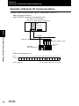
1
Sensor Communication Unit E3X-CRT (CompoNet) User's Manual Cat. No. E412-E1-01 Introduction Introduction Introduction Application Considerations (Please Read) Section 1 Overview Section 2 Installation and Connection Section 3 CompoNet Communication Settings Section 4 APPENDIX User's Manual Communication Unit for Digital Type Sensor E3X-CRT (CompoNet) E3X-DRT21-S User's Manual 1 Introduction Introduction READ AND UNDERSTAND THIS DOCUMENT Please read and understand this document before using the products. Please consult your OMRON representative if you have any questions or comments. WARRANTY OMRON’s exclusive warranty is that the products are free from defects in materials and workmanship for a period of one year (or other period if specified) from date of sale by OMRON. OMRON MAKES NO WARRANTY OR REPRESENTATION, EXPRESS OR IMPLIED, REGARDING NON-INFRINGEMENT, MERCHANTABILITY, OR FITNESS FOR PARTICULAR PURPOSE OF THE PRODUCTS. ANY BUYER OR USER ACKNOWLEDGES THAT THE BUYER OR USER ALONE HAS DETERMINED THAT THE PRODUCTS WILL SUITABLY MEET THE REQUIREMENTS OF THEIR INTENDED USE. OMRON DISCLAIMS ALL OTHER WARRANTIES, EXPRESS OR IMPLIED. LIMITATIONS OF LIABILITY OMRON SHALL NOT BE RESPONSIBLE FOR SPECIAL, INDIRECT, OR CONSEQUENTIAL DAMAGES, LOSS OF PROFITS OR COMMERCIAL LOSS IN ANY WAY CONNECTED WITH THE PRODUCTS, WHETHER SUCH CLAIM IS BASED ON CONTRACT, WARRANTY, NEGLIGENCE, OR STRICT LIABILITY. In no event shall responsibility of OMRON for any act exceed the individual price of the product on which liability is asserted. IN NO EVENT SHALL OMRON BE RESPONSIBLE FOR WARRANTY, REPAIR, OR OTHER CLAIMS REGARDING THE PRODUCTS UNLESS OMRON’S ANALYSIS CONFIRMS THAT THE PRODUCTS WERE PROPERLY HANDLED, STORED, INSTALLED, AND MAINTAINED AND NOT SUBJECT TO CONTAMINATION, ABUSE, MISUSE, OR INAPPROPRIATE MODIFICATION OR REPAIR. 2 E3X-CRT User’s Manual Introduction THE PRODUCTS CONTAINED IN THIS DOCUMENT ARE NOT SAFETY RATED. THEY ARE NOT DESIGNED OR RATED FOR ENSURING SAFETY OF PERSONS, AND SHOULD NOT BE RELIED UPON AS A SAFETY COMPONENT OR PROTECTIVE DEVICE FOR SUCH PURPOSES. Please refer to separate catalogs for OMRON’s safety rated products. Introduction SUITABILITY FOR USE OMRON shall not be responsible for conformity with any standards, codes, or regulations that apply to the combination of products in the customer’s application or use of the product. At the customer’s request, OMRON will provide applicable third party certification documents identifying ratings and limitations of use that apply to the products. This information by itself is not sufficient for a complete determination of the suitability of the products in combination with the end product, machine, system, or other application or use. The following are some examples of applications for which particular attention must be given. This is not intended to be an exhaustive list of all possible uses of the products, nor is it intended to imply that the uses listed may be suitable for the products: • Outdoor use, uses involving potential chemical contamination or electrical interference, or conditions or uses not described in this document. • Nuclear energy control systems, combustion systems, railroad systems, aviation systems, medical equipment, amusement machines, vehicles, safety equipment, and installations subject to separate industry or government regulations. • Systems, machines, and equipment that could present a risk to life or property. Please know and observe all prohibitions of use applicable to the products. NEVER USE THE PRODUCTS FOR AN APPLICATION INVOLVING SERIOUS RISK TO LIFE OR PROPERTY WITHOUT ENSURING THAT THE SYSTEM AS A WHOLE HAS BEEN DESIGNED TO ADDRESS THE RISKS, AND THAT THE OMRON PRODUCT IS PROPERLY RATED AND INSTALLED FOR THE INTENDED USE WITHIN THE OVERALL EQUIPMENT OR SYSTEM. PERFORMANCE DATA Performance data given in this document is provided as a guide for the user in determining suitability and does not constitute a warranty. It may represent the result of OMRON’s test conditions, and the users must correlate it to actual application requirements. Actual performance is subject to the OMRON Warranty and Limitations of Liability. E3X-CRT User’s Manual 3 Introduction Introduction CHANGE IN SPECIFICATIONS Product specifications and accessories may be changed at any time based on improvements and other reasons. It is our practice to change model numbers when published ratings or features are changed, or when significant construction changes are made. However, some specifications of the product may be changed without any notice. When in doubt, special model numbers may be assigned to fix or establish key specifications for your application on your request. Please consult with your OMRON representative at any time to confirm actual specifications of purchased products. DIMENSIONS AND WEIGHTS Dimensions and weights are nominal and are not to be used for manufacturing purposes, even when tolerances are shown. ERRORS AND OMISSIONS The information in this document has been carefully checked and is believed to be accurate; however, no responsibility is assumed for clerical, typographical, or proofreading errors, or omissions. PROGRAMMABLE PRODUCTS OMRON shall not be responsible for the user’s programming of a programmable product, or any consequence thereof. COPYRIGHT AND COPY PERMISSION This document shall not be copied for sales or promotions without permission. This document is protected by copyright and is intended solely for use in conjunction with the product. Please notify us before copying or reproducing this document in any manner, for any other purpose. If copying or transmitting this document to another, please copy or transmit it in its entirety. 4 E3X-CRT User’s Manual Introduction Introduction Meanings of Signal Words The following signal words are used in this manual. Indicates a potentially hazardous situation which, if not avoided, will result in minor or moderate injury, or may result in serious injury or death. Additionally there may be significant property damage. Alert statements in this Manual The following alert statements apply to the products in this manual. Each alert statement also appears at the locations needed in this manual to attract your attention. Configure the safety circuits, such as emergency stop circuits, interlock circuits, and limit circuits, with external control circuits in order to remain the safety of the entire system when a failure due to a product failure or an external factor occurs. If not, the failure may cause a serious incident. E3X-CRT User’s Manual 5 Introduction Introduction Precautions for Safe Use Please observe the following precautions for safe use of E3X-CRT. • Do not use the product in environments where it can be exposed to inflammable/ explosive gas. • Do not use the product where to be exposed to water, oil, chemical fumes or steam. • Do not disassemble, repair or modify this product. • Do not wire the product when the power is ON. • Do not drop, or subject to excessive shock or vibration. It may cause a failure or abnormal operation. • Use the specified communications cables. • Wire communications within the specified distance. • Do not wire the communications cables near or in parallel with high-voltage or highcurrent lines. • Do not bend cables past their natural bending radius or pull on cables. • Check all wiring carefully and completely before supplying power. • Confirm that the correct polarity has been used in wiring the terminals and that the communications and power lines have been otherwise wired correctly. Incorrect wiring may result in failure. • Do not connect or disconnect connectors while the power supply is turned ON. Doing so may result in failure or malfunction. • Use the specified power supply voltage. • Do not turn ON or OFF the power supply to the Mobile Console during communications. Doing so may result in communications errors. • Make sure that screws for the communication connector are tightened firmly. (0.5 N·m to 0.6N·m) • Do not use this product if the case is damaged. • Dispose this product as industrial waste. 6 E3X-CRT User’s Manual Introduction Introduction Precautions for Correct Use Please install this product correctly according to this manual. • Do not install the product in locations subjected to the following conditions: - Direct sunlight - Ambient temperature and humidity outside the rating - Rapid temperature transition and condensation - Excessive dust, saline air or metal powder - Direct vibration or shock • Use appropriate shielding when using this product in the following places. - Presence of noise such as static electric - Strong magnetic or electric field - Subject to possible expose to radiation - Near power supply lines • Do not clean with organic solvents, such as paint thinner. Organic solvents will dissolve and discolor the surface of the product. • Take measures to stabilize the power supply to conform to the rated supply (the voltage, frequency, etc.) if it is not stable. E3X-CRT User’s Manual 7 Introduction Introduction Editor’s Note Page Format Title of each section Header Overview of the header Section 4 DeviceNet Connection Settings DeviceNet Connection Settings Explanation of options DeviceNet supports different protocols for remote I/O communications between master and slave devices. Connection is a unit used to manage those protocols. The connections can be set using the configurator. The DeviceNet remote I/O communications protocol supports four types of connections: Poll, Bit-Strobe, COS (Change of state), and Cyclic. The features of these connections are listed in the following table. The Sensor communication unit supports all the protocols. Description Connection Used for basic I/O. Bit-Strobe Used for input of 8 bytes or less. Sends broadcasting requests from master and receives input from slaves. Poll and Bit-Strobe connections cannot be used at the same time. COS (Change of state) This connection can be used to send data to the master from the communication unit only when the data changes. Transmission timing is determined by a heartbeat timer. Data can be sent only when required, thereby reducing the communications load on the network. COS and Cyclic connections cannot be used at the same time. Cyclic Communications timing is determined by regular cycles (heartbeat timer). The communication unit will send data at a regular cycle. Section 4 APPENDIX Poll Index label Indicates the section number and title. Cross-header To use COS and Cyclic connections, the DeviceNet master must support those functions. Confirm that the master supports COS and Cyclic connections before using them. OMRON products, such as the CS1W-DRM21 and CJ1W-DRM21, support COS and Cyclic Overview of cross-header Setting Connections without using Configurator The connections used for all the IN data of the Sensor communication unit are as follows: Data of 8 bytes or less : Bit-Strobe Data of more than 8 bytes : Poll E3X-DRT21-S User's Manual 82 Supplementary Explanation Helpful information regarding operation and reference pages introduced here using symbols. * This page does not exist. 8 E3X-CRT User’s Manual Introduction Menu items that are displayed on the Amplifier Unit's LCD screen are indicated enclosed by brackets [ ]. Introduction ? Meaning of Symbols ? Visual Aids Indicates points that are important to ensure full product performance, such as operational precautions and application procedures. Indicates pages where related information can be found. Indicates information helpful in operation. Indicates functions that can be set only when the setup menu has been switched to EXP menu. E3X-CRT User’s Manual 9 Introduction Introduction 10 MEMO E3X-CRT User’s Manual Introduction Contents Introduction Contents Meanings of Signal Words 5 Precautions for Safe Use 6 Precautions for Correct Use 7 Editor’s Note 8 Page Format Contents Section 1 Overview Features and System Configuration 8 11 15 16 Overview 16 Features 17 System Configuration 18 Section 2 Installation and Connection Specifications and External Dimensions 19 20 Specifications 20 External Dimensions 21 Connecting Sensors 22 Connectable Sensors 22 Number of Connectable Sensors 23 Connecting and Identifying Sensors (Unit Number) 23 Registering the Number of Connected Sensors 24 Sensor Reset Switch 24 Installation 25 Installation Procedures 25 Removing Procedures 26 Precautions for Replacing Units 26 E3X-CRT User’s Manual 11 Introduction Contents Introduction Section 3 CompoNet Communication Settings Overview of CompoNet Communication Type 28 Overview 28 Overview of Communication Functions of CompoNet Communication Type 29 Example of Remote I/O Communications 32 Example of Explicit Message Communications 33 Part Names Part Names and Functions How to Use Units How to Use Units 34 34 37 37 Wiring CompoNet Communication Type 39 CompoNet Remote I/O Communications 40 Allocating to Master Explicit Message Communications 40 44 Basic Format of Explicit Messages 44 Read Commands 46 Write Commands 60 Operation Instruction Commands 70 Error Code List 72 Example of Explicit Message Functions 74 Sensor Setting/Monitoring/Operating Functions from Configurator 12 27 76 Overview 76 Setting the Communication Unit and Sensors, and Downloading 78 Uploading to Communication Unit and Monitoring/Setting Parameters Online 80 Operation Instructions for Each Sensor (Fiber Amplifier Unit) 81 Online Monitoring 82 Sensor Maintenance 82 E3X-CRT User’s Manual Introduction Contents Communications Timing Communications Timing 83 84 84 Errors and Countermeasures 86 CompoNet Connection Settings 88 Setting Connections without Using Configurator 88 Changing Connections Using the Configurator 89 CompoNet Device Profile 95 Device Profile 95 Mounted Objects 96 Index Revision History Introduction Section 4 APPENDIX 97 100 E3X-CRT User’s Manual 13 Introduction Contents Introduction 14 MEMO E3X-CRT User’s Manual Section 1 Section 1 Overview Section 1 Overview Features and System Configuration 16 Overview 16 Features 17 E3X-CRT User’s Manual 15 Section 1 Features and System Configuration Features and System Configuration Section 1 Overview Overview The Communication Unit (E3X-CRT) is a communication slave that performs the ON/OFF output for sensors, monitoring the detection level, writing parameters, and an operation between Digital Type Sensors and PLCs via CompoNet communication. (Supported sensors are: Fiber Sensors E3X-DA0-S/DAC0-S/MDA0, Separate Amplifier Laser Sensors E3X-LDA0, and Separate Amplifier Proximity Sensor E2C-EDA0.) The ON/OFF output and monitoring the detection level can be performed using remote I/O communications without any programming. Moreover, reading and writing any parameters using Explicit messages, and batch-transfer and monitoring any parameters using a configurator are possible. Device Net Optical Communication PLC 16 E3X-CRT User’s Manual Section 1 Features and System Configuration Features Section 1 Overview •This unit enables a communication interface between OMRON's PLCs (CS, CJ, SYSMAC and other series) or other manufacturer's PLCs that support CompoNet, and Digital Type Sensors. •Remote I/O communication slave Data such as ON/OFF output and the detection level on Digital Type Sensors can be sent to the upper (master) PLCs via remote I/O communication without any programming. •Message communications Sending commands (Explicit messages) from the PLC allows reading and writing parameters such as settings of the detection level, threshold and each function, and various teaching operations. E3X-CRT User’s Manual 17 Section 1 Overview E3X-CRT User’s Manual 18 Section 2 Section 2 Installation and Connection Section 2 Installation and Connection E3X-CRT User’s Manual 19 Section 2 Specifications and External Dimensions Specifications 21 External Dimensions 22 Connecting Sensors Section 2 Installation and Connection 20 21 23 Connectable Sensors 23 Number of Connectable Sensors 24 Connecting and Identifying Sensors (Unit Number) 24 Registering the Number of Connected Sensors 25 Sensor Reset Switch Installation 24 27 Installation Procedures 27 Removing Procedures 28 Precautions for Replacing Units 28 E3X-CRT User’s Manual Section 2 Specifications and External Dimensions Specifications and External Dimensions Specifications Description Communications method CompoNet Communications Communications Remote I/O communications ON/OFF output, status, and monitoring the detection level (details of the digital display) Message communications Setting parameters using Explicit messages Configurator Editing parameters for slave devices using a configurator/It depends on device monitoring functions Power supply Supplies from CompoNet communications connector (Power is supplied to all Sensors being connected via wire-saving connectors.) Maximum number of connected Sensors 15 or 16 (depending on the operating I/O-mode) Connectable Sensors Fiber Sensors Separate Amplifier Laser Sensors Separate Amplifier Proximity Sensors Refer to Connectable Sensors on page 23 for details. Power supply voltage DC14 to 26.4V Current consumption *1 70 mA max. Operating ambient temperature -20 to +55°C Operating ambient humidity 35% to 85% (with no condensation) Storage ambient temperature -30 to +70°C Size (mm) 41.5 (W) x 32.5 (H) x 102 (D) Weight **packed state Approx. 250 g Section 2 Installation and Connection Item *1. The current supplied to the Sensors is not included. E3X-CRT User’s Manual 21 Section 2 Specifications and External Dimensions External Dimensions Section 2 Installation and Connection 22 E3X-CRT User’s Manual Section 2 Connecting Sensors Connecting Sensors Connectable Sensors The Communication Unit can be connected with the following Sensors. Fiber Sensors Model Types Section 2 Installation and Connection Type Threshold value E3X-DA0-S Hi-grade type 2 E3X-DAC0-S Color type 2 E3X-MDA0 Sensor 2CH type 2 Separate Amplifier Laser Sensors E3C-LDA0 Two-output type 2 Separate Amplifier Proximity Sensors E2C-EDA0 Two-output type 2 Maximum number of connected any sensors can be connected is same. • E3X-CRT User’s Manual 23 Section 2 Connecting Sensors Number of Connectable Sensors The number of connectable Sensors depends on the settings of communication units. Type Setting CompoNet Communication Type (E3X-CRT) Section 2 Installation and Connection TMaximum Number of Connectable Sensors Remote I/O communications in 2CH mode Max. 15 Remote I/O communications in 4CH and out 4 CH mode Max. 16 number of connected any sensors can be connected is same. Connecting and Identifying Sensors (Unit Number) The Sensors are gang-mounted to the right side of the Communication Unit, as shown in the following diagram. DIN track must be used for installing. Power to the connected Sensors is supplied from the Communication Unit. Amplifier Unit Communication Unit for Sensor Sensor Heads DIN Track ON 0 1 8 9 3 7 2 6 0 x 10 1 3 7 2 8 9 5 NODE ADR 4 1234 4 x1 5 6 7 11 5 13 3 15 1 9 MS NS Slave Connectors of Sensors Unit 1 Unit 2 Unit 3 Unit 4 Unit 5 Unit 6 Unit 7 Unit 8 Unit 9 Unit 10 Unit 11 Unit 12 Unit 13 Unit 14 Unit 15 Unit 16 SS Connectors Unit numbers in ascending order from the left. The Communication Unit identifies the connected Sensors according to the unit numbers. Unit numbers of sensors are assigned to the units from unit number 1 starting from the communication unit side. Note that some Sensors occupy two unit numbers. 24 E3X-CRT User’s Manual Section 2 Connecting Sensors Registering the Number of Connected Sensors To detect whether communications between communication units and Sensors are normal, the number of connected Sensors must be registered. By registering the number of Sensors connected, when there is no response on the optical communications of Sensors due to damage to the Sensors and so on, errors can be Section 2 Installation and Connection detected from the difference between the number of Sensors that can be communicated with and the number of Sensors registered. When there is a difference between the number of Sensors connected and the number of Sensors registered, it is indicated as follows: • The SS LED lights red. • [Sensor Communication Error] Flag turns ON. Setting the Number of Connected Sensors Type E3X-CRT (CompoNet communications type) Setting method Registering using rotary switch. E3X-CRT User’s Manual 25 Section 2 Connecting Sensors Dummy Sensor Registering The sensor amplifier is not implemented is the ability to register as a dummy sensor. If you want to add more in the future sensor amplifiers, pre-set area (dummy sensor area) is secured. Thus, when the actual expansion, eliminating the need for significant changes in the ladder program. Section 2 Installation and Connection Or CX-Integrator, and you can check the contents set by the explicit message or CXintegrator. The setting way refer to explicit message in chapter 3. ex) Without dummy sensor setting Connected 5 Real sensors Unit 1 Real Sensor E3XCRT Unit 2 Real Sensor Unit 3 Real Sensor Unit 4 Real sensor Unit 5 Real Sensor Unit 4 Dummy Sensor Unit 5 Dummy Sensor ex) With dummy sensor setting Connected 5 Real sensors And Dummy sensor setting: Unit No. 4 and 5 Unit 1 Real Sensor #1 E3XCRT Unit 2 Real Sensor #2 Unit 3 Real Sensor #3 Unit 6 Real sensor #4 Unit 7 Real Sensor #5 T The registration number of connected Sensors (sensor number Rotary SW) include dummy sensors. The maximum number of “real sensors + dummy sensors” is 15 (I/O mode1) or 16(I/O mode2). Do not use empty Unit setting. For example Real sensor number is 1 and dummy sensor setting is No3 or greater. 26 E3X-CRT User’s Manual Section 2 Installation Installation Installation Procedures Installation procedures are as follows: Install the front part of the unit on the Section 2 Installation and Connection 1. Communication Unit DIN track. DIN Track 2. Press the rear part of the unit onto the DIN track. Press 3. Slide the Sensor Amplifier Unit to fit the hook of the connector to the communication unit, and keep pushing Sensor Amplifier Unit Communication Unit until you hear it snap into place. 4. Fix the both ends firmly with End Plate End Plate (PFP-M, sold separately). E3X-CRT User’s Manual 27 Section 2 Installation The order of steps 1 and 2 in the installation method described above 1 1 must be followed correctly. Mounting strength may decrease if the order is not correct. 2 2 Section 2 Installation and Connection Connector Connector Order of step (1) to step (2) NG as the order of step (2) to step (1) Removing Procedures Removing procedures are as follows: 1. Slide the Sensor Amplifier Unit to remove it from the communication unit. 2. Keep pressing the communication unit in direction A and lift it up in direction B to remove. A B Keep pressing it in direction A, in direction B and lift up. Precautions for Replacing Units The following parameters have been stored into the internal memory of the communications unit. If the default value have been changed, these parameters must be set again when replacing units. • Number of connected Sensors • Number of monitors for the detection level 28 E3X-CRT User’s Manual Section 3 Section 3 CompoNet Communication Settings Section 3 CompoNet Communication Settings E3X-CRT User’s Manual 27 Section 3 Overview of CompoNet Communication Type Overview 29 29 Overview of Communication Functions of CompoNet Communication Type30 Example of Remote I/O Communications 33 Example of Explicit Message Communications 34 Part Names Part Names and Functions How to Use Units How to Use Units 35 35 38 38 Section 3 CompoNet Communication Settings Wiring CompoNet Communication Type 38 CompoNet Remote I/O Communications 39 Allocating to Master Explicit Message Communications 39 44 Basic Format of Explicit Messages 44 Read Commands 47 Write Commands 59 Operation Instruction Commands 68 Error Code List 70 Example of Explicit Message Functions 72 Sensor Setting/Monitoring/Operating Functions from Configurator75 Overview 75 Setting the Communication Unit and Sensors, and Downloading77 Uploading to Communication Unit and Monitoring/Setting Parameters Online79 Operation Instructions for Each Sensor (Fiber Amplifier Unit)80 28 Online Monitoring 81 Sensor Maintenance 81 E3X-CRT User’s Manual Section 3 Overview of CompoNet Communication Type Overview of CompoNet Communication Type Overview A CompoNet Communication Type is a communication unit to output CompoNetON/OFF data of multiple fiber sensors, monitor the detection level, write parameters, and operate the unit via CompoNet. The ON/OFF output and monitoring the detection level can be performed using remote I/O communications without any programming. Moreover, reading and writing any parameters Section 3 CompoNet Communication Settings using Explicit messages, and batch-transfer and monitoring any parameters using a configurator are possible. When using this product, also refer to the following manuals: "CompoNet Slave Manual" (No. ????????????) E3X-CRT User’s Manual 29 Section 3 Overview of CompoNet Communication Type Overview of Communication Functions of CompoNet Communication Type Section 3 CompoNet Communication Settings 30 E3X-CRT User’s Manual Section 3 Overview of CompoNet Communication Type Remote I/O Communications The Communication Unit, E3X-CRT, can allocate sensor ON/OFF output data, status, and the detection level to the master IN area. CompoNet Unit CPU Unit Remote I/O Communications IN Area PLC Section 3 CompoNet Communication Settings Unit No. 1 ON/OFF output data Unit No. 2 ON/OFF output data Unit No. 13 ON/OFF output data Communicating with Sensor Example: For using the 1CH mode CompoNet ? Remote I/O Communications Communication Unit CompoNet Communication Type E3X-CRT Sensor Head Unit Unit No. No. 1 Unit No. 2 13 Amplifier Unit Communication Mode Occupied CH Communication Data Number of Sensors That Can Be Connected Master Unit I/O Mode 1 IN Area Remote I/O 2CH Communications IN 2CH mode Sending the following data to the master unit: Max. 15 - ON/OFF output data for maximum 15 units - Sensor Communication Error - Sensor Communication Busy - Read and write Sensor setting by explicit. For PLC Master Unit I/O Mode 2 Remote I/O Communication IN OUT 4CHmode Sending the following data to the master unit: Max. 16 - ON/OFF output data for maximum 16 units - Sensor Communication Error - Sensor Communication Busy - Read and write Sensor setting by original I/O command. So It can be changed the settting, by not using expicit. - Read and write Sensor setting by explicit. For Gateway IN Area 4CH + OUT Area 4CH E3X-CRT User’s Manual 31 Section 3 Overview of CompoNet Communication Type Explicit Message Communications Any parameters of the connected sensors can be read or written by issuing commands of Explicit messages to the Communication Unit (E3X-CRT). CompoNet Unit CPU Unit PLC Ladder Program e.g. CMND command Section 3 CompoNet Communication Settings ? Explicit Message Communications CompoNet Sensor Head Communication Unit CompoNet Communication Type E3X-CRT 1 2 Unit No. 13 Amplifier Unit Type 32 Unit Unit No. No. Communication Data Condition Sends an Explicit Read command Reads any parameters such as the ON/ Not allowed when connected OFF output data, the detection level, and with the Mobile Console. threshold values Sends an Explicit Write command Writes (sets) any parameters such as threshold values Sends an Explicit Operation Instruction command Various operations such as teaching E3X-CRT User’s Manual Section 3 Overview of CompoNet Communication Type Transferring, Monitoring, and Operating from the Configurator A CX-Integrator can be used to read and write Sensor parameters from a personal computer. CX-Integrator CS/CJ series CompoNet unit Section 3 CompoNet Communication Settings PLC Serial connection Sensor settings monitor/operation functions by the Configurator: ? Various settings and downloading for sensors ? Monitoring the sensor ON/OFF output data, the detection level, and more ? Sensor teaching operations CompoNet Sensor Head CompoNet slave Communication Unit CompoNet Communication Type Type Communication Data Sensor parameter setting Writes (sets) any parameters such as threshold values Sensor monitoring Reads any parameters such as the ON/ OFF output data, the detection level, and threshold values Sensor teaching Performs various teaching operations Condition Not allowed when connected with the Mobile Console E3X-CRT User’s Manual 33 Section 3 Overview of CompoNet Communication Type Example of Remote I/O Communications Example: When monitoring sensor ON/OFF output state of unit No. 1 When using the I/O Mode 1 When E3X-CRT CompoNet node address is 00. CompoNet unit (CS1W-DRM21) Remote I/O communication fix assignment CS1 CPU Unit IN Area Section 3 CompoNet Communication Settings 34 CompoNet Reflected in the IN Area Monitors ON/OFF output E3X-CRT Node Address 00 of the Unit No.1 IN Area (Fix Assignment 1) Bit 15 14 13 12 11 10 09 08 07 06 05 04 03 02 01 00 3300CH Node Address 00 E3X-CRT User’s Manual Sensor ON/OFF output state of unit No. 1 Section 3 Overview of CompoNet Communication Type Example of Explicit Message Communications Example: When setting maximum sensitivity to unit No. 1 CompoNet unit (CS1W-CRM21) Unit number 0 (unit No. address: FEHex or 10Hex) CompoNet node address CS1 CPU Unit CMND command CompoNet Section 3 CompoNet Communication Settings Sensors Explicit Messages Unit No. 1 Set maximum sensitivity to this unit. E3X-CRT Node Address 00 • Command Format for Setting Maximum Sensitivity Send the following Explicit messages: Destination Node Address Service Code 00Hex 16 Hex Executing Condition A20200 Network communications enabled S: Class ID Instance ID 009EHex 0001Hex Attribute ID 30Hex 151100 or 152412 Online state or message communications enabled CMND D01000 D02000 D00000 Command data of 10 bytes from D01000 is sent to destination node address 05, then its response data of 10 bytes is stored into D02000 of the local node (D00000 is control data) D01000 2 8 0 1 Command code D01001 0 0 1 6 Slave node address: 00, ServiceCode: 16Hex D01002 0 0 9 C ClassID: 009CHex D01003 0 0 0 1 InstanceID: 0001Hex (unit No.) D01003 3 0 0 0 Data: 30Hex (Fixed) D: D02000 C: D00000 0 Head CH number for response store 0 0 9 Byte length of command data: 9 D00001 0 0 0 A Byte length of response data D00002 0 0 0 1 Destination network address: 1 D00003 0 5 F E Destination CompoNet node address: 05Hex Destination unit No. address: FEHex (10Hex is also acceptable) D00004 0 0 0 0 Response required, communication port No. 0, retry number: 0Hex D00005 0 0 C 8 Response monitoring timer: 20 seconds E3X-CRT User’s Manual 35 Section 3 Part Names Part Names Part Names and Functions DIP switch Rotary Switches Section 3 CompoNet Communication Settings Sensor Reset Switch By turning ON the connected sensors, you can reset them. Display Communication Connector This is a CompoNet communication connector. Power Supply Connector Since electricity is supplied from a communication connector for E3X-CRT, there is no cable for power supply. Indicator (LED) The following table shows the operation of the indicators. LED Name MS Name Module Status LED Color Green Status Lit Description Normal operation Flashing Not set Red Lit Fatal error — Not lit. Power OFF Green Lit CompoNet online/connected Flashing Non-fatal error NS Network Status Flashing CompoNet online/not-connected Red Lit CompoNet fatal communication error — Not lit. CompoNet offline/power OFF Green Lit Communicating with Sensor Flashing CompoNet non-fatal communication error SS 36 E3X-CRT User’s Manual Sensor Communication Status Red Lit Sensor communications error — Not lit. Waiting for communications with the sensors/ power OFF Section 3 Part Names Normal State of LEDs MS Green is lit when normal NS Green is lit: normal (online/connected) SS Green is lit when communicating with a sensor Switches Section 3 CompoNet Communication Settings E3X-CRT User’s Manual 37 Section 3 Part Names Rotary Switches x10 x1 CompoNet node address setting Sets the CompoNet node address. Range: Between 00 and 63 (cannot be set between 64 and 99) Registering the Number of Connected Sensors Registers the number of sensors to be connected. Registering the number of the sensors enables you to detect configuration failure when it occurs. The Sensors that are allocated two unit numbers must be counted as two units when counting the Section 3 CompoNet Communication Settings number of sensors. 38 E3X-CRT User’s Manual Section 3 Part Names DIP switch • I/O Mode Settings This switche set the I/O mode. However, data type assigned to the master IN area varies on the operating mode.For details, see ?CompoNet Remote I/O Communications? on p. 39. I/O mode Operating Mode Settings Number of Sensors that Can Be Connected Remote I/O communications IN 2CH mode Max. 15 2 Remote I/O communications IN 4CH OUT 4CH mode Max. 16 Section 3 CompoNet Communication Settings 1 In E3X-CRT, CompoNet baud rate is automatically changed to baud rate of the master. Therefore, the DIP switch is not required to set the baud rate. E3X-CRT User’s Manual 39 Section 3 How to Use Units How to Use Units How to Use Units Step 1 Item Mount the Communication Unit to the DIN Track Description Mount this unit to the DIN track. After the Sensor Amplifier Unit is mounted to the DIN track, gang-mount the Sensor Amplifier Unit. When you dismount a unit from the track, slide the body, Section 3 CompoNet Communication Settings disconnect the connection, and then dismount it from the DIN track. Slide the Communication Unit, touch its edge clip onto the sensor amplifier unit, and then stick it to the amplifier unit tightly until a clinking noise is heard. 2 Connect Sensors to the Communication Unit 3 Set the Sensors to "RUN" Mode By using the mode switch, set "RUN" mode. 4 CompoNet Connect a connector for CompoNet communication. Connecting a CompoNet Communication Power Supply provides DC electricity to Communication Connector the Communication Unit and all connected sensors. 5 Set the Rotary Switches Two upper Set the CompoNet node address (between 0 and 62). switches One lower Set the number of connected sensors (between 1 and 16) switch The Sensors that are allocated two unit numbers must be counted as two units when counting the number of sensors. 6 Set the DIP Switches 7 DC Power Supply Turn on CompoNet Communication Power Supply 8 Check the LEDs I/O mode1 IN 2CH Mode I/O mode2 IN 4CH + OUT 4CH Mode 9 Communications Start • Set the sensors to [RUN] mode. MS Green is lit when normal NS Green is lit: normal (CompoNet online/connected) SS Green is lit when communicating with a sensor When remote I/O communications Enable the scan list of the master side to change PLC to [Running] mode. When Explicit message Send Explicit messages from the master side. communications 40 E3X-CRT User’s Manual Section 3 CompoNet Remote I/O Communications CompoNet Remote I/O Communications Allocating to Master Data of E3X-CRT is stored in the IN area of the CompoNet master. Select one of the following three modes using the DIP switch I/O mode Operating Mode Settings Number of Sensors that Can Be Connected Remote I/O communications IN 2CH mode Max. 15 2 Remote I/O communications IN 4CH OUT 4CH mode Max. 16 Section 3 CompoNet Communication Settings 1 Remote I/O Communications IN 2CH Mode (I/O Mode = 1) Up to 15 sensors can be connected. The IN area occupies 2CH of the master. Unit numbers of sensors are automatically assigned to the units from unit number 1 starting from the communication unit side (left). M CH Bit Description M+1 CH Bit Description 00 Unit No. 1 ON/OFF output1 data 00 Unit No. 9 ON/OFF output1 data 01 Unit No. 1 ON/OFF output2 data 01 Unit No. 9 ON/OFF output2 data 02 Unit No. 2 ON/OFF output1 data 02 Unit No. 10 ON/OFF output1 data 03 Unit No. 2 ON/OFF output2 data 03 Unit No. 10 ON/OFF output2 data 04 Unit No. 3 ON/OFF output1 data 04 Unit No. 11 ON/OFF output1 data 05 Unit No. 3 ON/OFF output2 data 05 Unit No. 11 ON/OFF output2 data 06 Unit No. 4 ON/OFF output1 data 06 Unit No. 12 ON/OFF output1 data 07 Unit No. 4 ON/OFF output2 data 07 Unit No. 12 ON/OFF output2 data 08 Unit No. 5 ON/OFF output1 data 08 Unit No. 13 ON/OFF output1 data 09 Unit No. 5 ON/OFF output2 data 09 Unit No. 13 ON/OFF output2 data 10 Unit No. 6 ON/OFF output1 data 10 Unit No. 14 ON/OFF output1 data 11 Unit No. 6 ON/OFF output2 data 111 Unit No. 14 ON/OFF output2 data 12 Unit No. 7 ON/OFF output1 data 12 Unit No. 15 ON/OFF output1 data 13 Unit No. 7 ON/OFF output2 data 13 Unit No. 15 ON/OFF output2 data 14 Unit No. 8 ON/OFF output1 data 14 Busy (Communicating with Sensor) 15 Unit No. 8 ON/OFF output2 data 15 Sensor communications error • Busy (Communicating with Sensor): When the communication with a sensor is established, it is turned ON. • Sensor communications error: When the registered number of connected sensors doesn’t match the number of sensors that can be communicated, or when communications with a sensor fail after the connection with the sensor is established, it is turned ON. E3X-CRT User’s Manual 41 Section 3 CompoNet Remote I/O Communications Remote I/O Communications IN 4CH + OUT 4CH Mode (I/O Mode = 2) Up to 16 sensors can be connected. Sensor setting can be changed by only using I/O area.(Without explicit). IN m CH, m + 1 CH M CH Bit M+1 CH Bit Description Description Section 3 CompoNet Communication Settings 00 Unit No. 1 ON/OFF output1 data 00 Unit No. 9 ON/OFF output1 data 01 Unit No. 1 ON/OFF output2 data 01 Unit No. 9 ON/OFF output2 data 02 Unit No. 2 ON/OFF output1 data 02 Unit No. 10 ON/OFF output1 data 03 Unit No. 2 ON/OFF output2 data 03 Unit No. 10 ON/OFF output2 data 04 Unit No. 3 ON/OFF output1 data 04 Unit No. 11 ON/OFF output1 data 05 Unit No. 3 ON/OFF output2 data 05 Unit No. 11 ON/OFF output2 data 06 Unit No. 4 ON/OFF output1 data 06 Unit No. 12 ON/OFF output1 data 07 Unit No. 4 ON/OFF output2 data 07 Unit No. 12 ON/OFF output2 data 08 Unit No. 5 ON/OFF output1 data 08 Unit No. 13 ON/OFF output1 data 09 Unit No. 5 ON/OFF output2 data 09 Unit No. 13 ON/OFF output2 data 10 Unit No. 6 ON/OFF output1 data 10 Unit No. 14 ON/OFF output1 data 11 Unit No. 6 ON/OFF output2 data 11 Unit No. 14 ON/OFF output2 data 12 Unit No. 7 ON/OFF output1 data 12 Unit No. 15 ON/OFF output1 data 13 Unit No. 7 ON/OFF output2 data 13 Unit No. 15 ON/OFF output2 data 14 Unit No. 8 ON/OFF output1 data 14 Unit No. 16 ON/OFF output1 data 15 Unit No. 8 ON/OFF output2 data 15 Unit No. 16 ON/OFF output2 data IN m + 2 CH, m + 3 CH 15 m + 2CH SERR 14 13 12 11 10 BUSY BU Reserved _MS SY _I G O m + 3CH 09 08 07 06 05 Norm _res Err_re Error Data s 04 03 02 Response Data OUT 15 m CH m + 1CH 42 TRG 14 13 12 11 10 09 08 07 06 Sensor Unit No. 03 02 Sensor Output1/ Output2 Command m + 3CH Command Data User’s Manual 04 Reserved m + 2CH E3X-CRT 05 01 00 01 00 Section 3 CompoNet Remote I/O Communications Input • S-ERR: Sensor communications error: When the registered number of connected sensors doesn’t match the number of sensors that can be communicated, or when communications with a sensor fail after the connection with the sensor is established, it is turned ON.S-ERR • Busy-MSG (Communicating with Sensor by explicit message): When the communication with a sensor is established, it is turned ON. • Busy-IO (Communicating with Sensor by I/O): When the communication with a sensor is established, it is turned ON. • Norm-RES (Normal end and Response DATA): Section 3 CompoNet Communication Settings When the communication with a sensor success and return data, it is turned ON. • ERR-RES (Error end and Response Error DATA): When the communication with a sensor didn’t success and return error data, it is turned ON. • ERR-DATA (Error DATA): Error reason data. • Response DATA Response data from E3X-CRT or Sensor Amplifier. The data pattern is same as Explicit message Response data. Output • TRG: Command Execute Trigger When this bit is turned ON E3X-CRT Execute command, conform to “Sensor Unit No.”, “Output1/2”, “Command”, “Command Data”. • Sensor Unit No. This area assign Sensor Unit No. from 01 to 10 • Sensor Output1/Output2 This area assign Sensor Output 1 or 2 • Command This area assign command. Refer to next page. • Command Data This area assign command data. The data is same as explicit message. • E3X-CRT User’s Manual 43 Section 3 CompoNet Remote I/O Communications Command List Command Section 3 CompoNet Communication Settings 44 Read Write Operate Read status 00 - - Read detection level 20 - - Continuous read detection level 21 - - When detected (ON) read detection level 22 - - When detected (ON) continuous read detection level 23 - - When detected (OFF) read detection level 24 - - When detected (OFF) continuous read detection level 25 - - Threshold Settings 80 C0 - Differentiation Threshold Settings 85 C5 - Difference Threshold Settings 8D CD - Operating Mode Settings 86 C6 - Detection Function Settings 88 C8 - Differentiation Edge Settings 89 C9 - Differentiation mode Response Time 8A CA - Timer Function Settings 8B CB - Timer Time Settings 8C CC - Display Switching Settings 8F CF - MODE Key Settings 90 D0 - Display Direction Settings 91 D1 - Power Tuning Target Value Settings 92 D2 - Output Settings 93 D3 - Teaching Level Settings without a Workpiece 96 D6 - Power Tuning Threshold Settings 97 D7 - ATC Function at Power Supply ON Settings 98 D8 - ATC Function Settings 99 D9 - "Eco" Mode Settings 9A DA - Zero Reset Level 26 - - Power tuning situation 27 - - Threshold Ratio Settings 9B DB - Key Lock Settings 9D DD - Number of Connected Sensors 01 - - Set maximum sensitivity - - 40 Teaching without a Reflective Type Workpiece - - 41 Teaching without a Through-beam Type Workpiece - - 42 Teaching with the workpiece or without a workpiece(the First Point) - - 43 Teaching with the workpiece or without a workpiece (the Second Point) - - 44 Position Teaching(DA7 is executed by Teaching with the workpiece or without a workpiece) - - 45 Start Auto Teaching - - 46 Stop Auto Teaching - - 47 E3X-CRT User’s Manual Section 3 CompoNet Remote I/O Communications Command Read Write Operate Execute Power Tuning - - 48 Cancel Power Tuning - - 49 Execute Zero Reset - - 4A Cancel Zero Reset - - 4B Execute Projection Lighting Off - - 4C Cancel Projection Lighting Off - - 4D Sensor Reset - - 02 Section 3 CompoNet Communication Settings E3X-CRT User’s Manual 45 Section 3 Explicit Message Communications Explicit Message Communications Sending a CompoNet Explicit message from the master to the Communication Unit enables reading and writing any parameters of the specified sensor. The Communication Unit processes the command sent from the master and then returns a response. Basic Format of Explicit Messages The basic format of each command and response is shown below: Section 3 CompoNet Communication Settings 46 E3X-CRT User’s Manual Section 3 Explicit Message Communications Command Format Destination Node Address Service Code Class ID Instance ID Attribute ID Data [Destination Node Address] Specify a node address of the unit that an Explicit message (command) is sent to. The node address must be a single byte in hexadecimal. [ServiceCode], [Class ID], [Instance ID], [Attribute ID] Section 3 CompoNet Communication Settings These are parameters to specify a command type, process target, and process details. The Communication Unit uses the [Instance ID] to specify to sensors for which the command is intended (Sensor number.) Each sensor has 2 sensor number(output1 and output2). So Sensor number 5 means Unit number 3, output 1. Some commands do not require an [Attribute ID]. Depending on the master, each length of [Class ID], [Instance ID], and [Attribute ID] might be different. When a message is sent from an Omron CompoNet master, specify a [Class ID] and an [Instance ID] in two bytes as four digits, and an [Attribute ID] in a single byte as two digits. [Data]: Data is not required when using a Read command. E3X-CRT User’s Manual 47 Section 3 Explicit Message Communications Response Format • Normal Number of Received Bytes Source Node Address Service Code Data • Failure Number of Received Bytes: 0004Hex (Fixed) Source Node Address Service Code Error Code [Number of Received Bytes] The number of the received data starting from the [Source Node Address] is returned in hexadecimal. When an error response is returned to the Explicit message, the value Section 3 CompoNet Communication Settings 48 always will be 0004Hex. [Source Node Address] The node address of the node that sent the command is returned in hexadecimal. E3X-CRT User’s Manual Section 3 Explicit Message Communications [ServiceCode] When the command is completed normally, the leftmost bit of the [ServiceCode] specified in the command is turned ON and stored as follows: ServiceCode of the Command ServiceCode of the Response 10 Hex 90 Hex 0E Hex 8E Hex 16 Hex 96 Hex 06 Hex 86 Hex 07 Hex 87 Hex 05 Hex 85 Hex Section 3 CompoNet Communication Settings When an error message is returned to the Explicit message, the value always will be 94Hex. [Data]: The read data is stored only when a read command has been sent. [Error Code]: An error code for the Explicit message. ?Error Code List? on p. 70 E3X-CRT User’s Manual 49 Section 3 Explicit Message Communications Read Commands A Read command reads data of a connected sensor or communication unit. When using an OMRON master, command/response formats are shown as follows: Section 3 CompoNet Communication Settings 50 E3X-CRT User’s Manual Section 3 Explicit Message Communications Command Format Destination Service Node Code Address Class ID Instance ID Attribute ID 2 bytes 2 bytes 1 byte 0E (Fixed) 1 byte 1 byte Section 3 CompoNet Communication Settings E3X-CRT User’s Manual 51 Section 3 Explicit Message Communications Response Format • Normal Length of Received Bytes Destination Service Node Code Address 0004 Read Data 8E (Fixed) 2 bytes 1 byte 1 byte 2 bytes (*1) • Error Section 3 CompoNet Communication Settings Length of Received Bytes Destination Service Node Code Address 0004 2 bytes 94 (Fixed) 1 byte 1 byte 2 bytes Read Command List A list of Explicit Message Read commands is shown below. [Supported Models] E3X-DA0-S: DA, E3X-MDA0: MDA E3C-LDA0: LDA E2C-EDA0: EDA Command Explicit Messages Read status 52 Error Code Functions Attribute ID Supported Model AA — Read detection level With specifying a Unit No. with the Instance 9F ID, reads the digital detection level. Sensor Number 82 All models When detected (ON) With specifying a Unit No. with the Read detection level Instance ID, reads the detection level when detected (ON). 9F Sensor Number 96 All models When detected (ON) With specifying a Unit No. with the Read detection level Instance ID, reads the detection level when not detected (OFF). 9F Sensor Number 97 All models Read Threshold Settings 9C Sensor Number 11 All models Read Differentiation With specifying a Unit No. with the Instance 9C Threshold Settings ID, reads the differentiation mode threshold. Sensor Number 10 Except MDA Read Difference Threshold Settings With specifying a Unit No. with the Instance ID, reads the threshold value when the difference outputs. 9C Sensor Number 12 MDA Read Operating Mode Settings With specifying a Unit No. with the Instance ID, reads the operating mode. 9C Sensor Number 20 All models User’s Manual With specifying a Unit No. with the Instance ID, reads the threshold value. 9F Instance ID 0 E3X-CRT Reads the status of the sensor communication unit. Class ID Section 3 Explicit Message Communications Command Explicit Messages Functions Class ID Instance ID Attribute ID Supported Model With specifying a Unit No. with the Instance ID, reads the detection mode. 9C Sensor Number 21 All models Read Differentiation Edge Settings With specifying a Unit No. with the Instance ID, reads the differentiation edge. 9C Sensor Number 22 Except MDA Differentiation mode With specifying a Unit No. with the Read Response Instance ID, reads the differentiation Time mode response time. 9C Sensor Number 23 Except MDA Read Timer Function Settings With specifying a Unit No. with the Instance ID, reads the timer function. 9C Sensor Number 24 All models Read Timer Time Settings With specifying a Unit No. with the Instance ID, reads the timer time. 9C Sensor Number 25 All models Read Display Switching Settings With specifying a Unit No. with the Instance 9C ID, reads the display switching settings. Sensor Number 26 All models Read MODE Key Settings With specifying a Unit No. with the Instance ID, reads the MODE key settings. 9C Sensor Number 27 All models Read Display Direction Settings With specifying a Unit No. with the Instance ID, reads the display direction settings. 9C Sensor Number 28 All models Read Power Tuning With specifying a unit No. with the Instance 9C Target Value Settings ID, reads the power tuning target value. Sensor Number 29 All models Read Output Settings 9C Sensor Number 2A All models Read Teaching With specifying a Unit No. with the Level Settings Instance ID, reads the teaching level without a Workpiece settings without a workpiece. 9C Sensor Number 4B All models Read Power Tuning Threshold Settings 9C Sensor Number 40 All models Read ATC Function With specifying a Unit No. with the Instance 9C at Power Supply ON ID, reads ATC function at power supply ON settings. Settings Sensor Number 42 DA Read ATC Function Settings With specifying a Unit No. with the Instance 9C ID, reads ATC function settings. Sensor Number 44 DA Read "Eco" Mode Settings With specifying a Unit No. with the Instance 9C ID, reads the "Eco" mode settings. Sensor Number 45 All models Read Zero Reset Level With specifying a Unit No. with the Instance ID, reads the zero reset level. 9C Sensor Number 48 All models Read Threshold Ratio Settings With specifying a Unit No. with the Instance ID, reads threshold ratio settings. 9C Sensor Number 4E DA Read Key Lock Settings With specifying a Unit No. with the Instance ID, reads the key lock settings. 9C Sensor Number 50 All models Read Number of Connected Sensors Reads the number of connected sensors. 9C 0 57 — With specifying a Unit No. with the Instance ID, reads the output settings. With specifying a Unit No. with the Instance ID, reads the power tuning threshold settings. E3X-CRT User’s Manual Section 3 CompoNet Communication Settings Read Detection Function Settings 53 Section 3 Explicit Message Communications Command Explicit Messages Functions Class ID Instance ID Attribute ID Read Dummy units setting Read Dummy units setting 9C 0 71 Read dummy response setting Read dummy response setting 9C 0 70 Supported Model A range of unit Nos. in the Instance ID should be between 0001Hex and 0020Hex. Section 3 CompoNet Communication Settings 54 Data format of each item is shown below: E3X-CRT User’s Manual Section 3 Explicit Message Communications Read Status Bit Description Bit Description Number of connected sensors (20) 08 Number of sensors that can be communicated with (20) 01 Number of connected sensors (21) 09 Number of sensors that can be communicated with (21) 02 Number of connected sensors (22) 10 Number of sensors that can be communicated with (22) 03 Number of connected sensors (23) 11 Number of sensors that can be communicated with (23) 04 Number of connected sensors (24) 12 Number of sensors that can be communicated with (24) 05 Reserved 13 Reserved 06 Reserved 14 Sensor communications error 07 Reserved 15 Communicating with Sensor Section 3 CompoNet Communication Settings 00 • Number of connected sensors: The number of current connected sensors that are already registered is shown in hexadecimal. • Number of sensors that can be communicated with: The number of current sensors that can be communicated with is shown in hexadecimal. When failure occurs, you can confirm how many sensors are communicating successfully. • Communicating with Sensor: When the communication with a sensor is established, it is turned ON. • Sensor communications error: When the registered number of connected sensors doesn’t match the number of sensors that can be communicated, or when communications with a sensor fail after the connection with the sensor is established, it is turned ON. E3X-CRT User’s Manual 55 Section 3 Explicit Message Communications Read the detection level/read the detection level on detected (ON)/ read the detection level on undetected (OFF) These commands read the detection level of the sensor with the unit No. specified with the Instance ID. Those data is shown in hexadecimal as a four-digit value (two bytes). If the data is negative, the 12th bit is 1 (on). Detection level Section 3 CompoNet Communication Settings 56 Bit 15 Bit 14 0 Fixed Bit 13 Bit 12 0: + / 1: - Bit 11 Bit 10 Bit 09 Bit 08 Bit 07 Bit 06 Bit 05 Bit 04 Bit 03 Bit 02 Bit 01 Bit 00 The detection level (000Hex to FA0Hex) Read Detection level on Detected (ON) and Read Detection level on Undetected (OFF) can read the detection level only when the display switching settings are peak on detected and bottom on undetected. Also, its data range is between F831Hex (complement of 2) and 0FA0Hex. E3X-CRT User’s Manual Section 3 Explicit Message Communications Read threshold settings/read threshold settings on differentiation mode/read threshold settings on difference outputs These commands read threshold settings of the sensor with the unit No. specified with the Instance ID. Data is shown in hexadecimal, and the data for each single unit is 16bits long. If the data is negative, the 12th bit is 1 (on). Threshold settings Bit 15 Bit 14 Bit 12 0: + / 1: - Bit 11 Bit 10 Bit 09 Bit 08 Bit 07 Bit 06 Bit 05 Bit 04 Bit 03 Bit 02 Bit 01 Bit 00 Section 3 CompoNet Communication Settings 0 Fixed Bit 13 Threshold setting (0000Hex to 0FA0Hex) Depending on the sensor type, [Read Differentiation Threshold Settings] and [Read Difference Threshold Settings] might not be able to be performed correctly. E3X-CRT User’s Manual 57 Section 3 Explicit Message Communications Read Operating Mode Settings It reads the operating mode settings of the sensor with the unit No. specified with the Instance ID. Bit Data 00 Operating mode E3X, E3C: 0: L/ON, 1: D/ON; E2C: 0: NO, 1: NC 01 to 15 No data Always 0 Section 3 CompoNet Communication Settings 58 Description E3X-CRT User’s Manual Section 3 Explicit Message Communications Read Detection Function Settings It reads the operating mode settings of the sensor with the unit No. specified with the Instance ID. Bit 00 Description Detection mode 01 02 03 to 15 No data Data 0: STAND, 1: HI-RESO, 2: Differentiation, 4: High speed, 6: Tough(DA7) Always 0 Note that some models cannot be set to the high speed mode. Section 3 CompoNet Communication Settings E3X-CRT User’s Manual 59 Section 3 Explicit Message Communications Read Differentiation Edge Settings It reads the differentiation edge settings of the sensor with the unit No. specified with the Instance ID. Bit Data Operating mode 0: Single-end edge, 1: Double-end edge 01 to 15 No data Always 0 Section 3 CompoNet Communication Settings 60 Description 00 E3X-CRT User’s Manual Section 3 Explicit Message Communications Read Differentiation Response Speed Settings It reads the differentiation response speed settings of the sensor with the unit No. specified with the Instance ID. Bit 00 01 Description 1: Differentiation response speed setting 1 2: Differentiation response speed setting 2 3: Differentiation response speed setting 3 4: Differentiation response speed setting 4 5: Differentiation response speed setting 5 No data Always 0 02 03 04 to 15 Data Differentiation response time Section 3 CompoNet Communication Settings E3X-CRT User’s Manual 61 Section 3 Explicit Message Communications Read Timer Function Settings It reads the timer function settings of the sensor with the unit No. specified with the Instance ID. Bit 00 Description 0: Timer function disabled 1: OFF-delay timer 2: ON-delay timer 3: One-shot timer 4: ON-delay and OFF-delay timer No data Always 0 01 02 to 15 Section 3 CompoNet Communication Settings 62 E3X-CRT User’s Manual Data Timer function Section 3 Explicit Message Communications Read Timer Time Settings/Read ON-Delay timer time Settings/Read OFF-Delay timer time Settings It reads the timer time settings of the sensor with the unit No. specified with the Instance ID. Its read data is expressed in hexadecimal and its length is two bytes; the data range is between 0000hex (0) and 1388hex (5000). When the timer function setting is OFF, [Read Timer Time Settings] command fails if the command is sent. Section 3 CompoNet Communication Settings E3X-CRT User’s Manual 63 Section 3 Explicit Message Communications Read Display Switching It reads the display switching settings of the sensor with the unit No. specified with the Instance ID. Bit 00 01 02 Description 0: Detection level and detection level (MDA) 1: Detection level and threshold 2: Detection level ratio and threshold 3: Peak on detected and bottom on undetected 4: Detection level at peak and detection level at bottom (time update) (E3X, E3C are bottom on detected and peak on undetected) 5. Analog bar 6: Detection level and peak digital values 7: Detection level and channel number 8: Count value (RM, LDARM) No data Always 0 03 Section 3 CompoNet Communication Settings 64 04 to 15 E3X-CRT User’s Manual Data Display switching setting Section 3 Explicit Message Communications Read MODE Key Settings It reads the MODE key settings of the sensor with the unit No. specified with the Instance ID. Bit 00 01 Description 0: E3X, E3C: Power tuning, E2C: Fine positioning 1: Zero reset 2: Counter reset (RM, LDARM) 3: Position teaching (E2C) 4: Teaching with the workpiece or without a workpiece No data Always 0 02 03 to 15 Data MODE key setting Section 3 CompoNet Communication Settings E3X-CRT User’s Manual 65 Section 3 Explicit Message Communications Read Display Direction Settings It reads the MODE key settings of the sensor with the unit No. specified with the Instance ID. Bit Data 00 Display direction setting 0: Normal, 1: Vertical reverse 04 to 15 No data Always 0 Section 3 CompoNet Communication Settings 66 Description E3X-CRT User’s Manual Section 3 Explicit Message Communications Read Power Tuning Target Value Settings It reads the power tuning target value settings of the sensor with the unit No. specified with the Instance ID. Its read data is expressed in hexadecimal and its length is two bytes; the data range is between 0064hex (100) and 0F3Chex (4000). Section 3 CompoNet Communication Settings E3X-CRT User’s Manual 67 Section 3 Explicit Message Communications Read Output Settings It reads the output settings of the sensor with the unit No. specified with the Instance ID. Bit 00 Description 0: Output for each channel 1: Area output (TW, LDATW, EDATW) 2: Self diagnosis output (TW, LDATW, EDATW) 3: AND output (MDA) 4: OR output (MDA) 5: Difference output (MDA) 6: Rising edge sync output (MDA) 7: Down edge sync output (MDA) 8: Head error output (E2C) No data Always 0 01 02 03 Section 3 CompoNet Communication Settings 68 04 to 15 E3X-CRT User’s Manual Data Output settings Section 3 Explicit Message Communications Read Output Setting Timer Function Settings It reads the output setting timer function settings of the sensor with the unit No. specified with the Instance ID. Bit 00 Description Data 01 Output setting timer function 0: Timer function disabled 1: OFF-delay timer 2: ON-delay timer 3: One-shot timer 02 to 15 No data Always 0 Section 3 CompoNet Communication Settings E3X-CRT User’s Manual 69 Section 3 Explicit Message Communications Read Output Setting Timer Time Settings It reads the output timer time settings of the sensor with the unit No. specified with the Instance ID. Its read data is expressed in hexadecimal and its length is two bytes; the data range is between 0000hex (0) and 1388hex (5000). When the output setting timer function setting is OFF, [Output Setting Timer Time Settings] command fails if the command is sent. Section 3 CompoNet Communication Settings 70 E3X-CRT User’s Manual Section 3 Explicit Message Communications Read Teaching Level Settings without a Workpiece It reads the teaching level settings without a workpiece of the sensor with the unit No. specified with the Instance ID. Its read data is expressed in hexadecimal and its length is two bytes; the data range is between 00hex (0) and 63hex (99). Section 3 CompoNet Communication Settings E3X-CRT User’s Manual 71 Section 3 Explicit Message Communications Read Power Tuning (Fine Positioning) Settings It reads the power tuning (fine positioning) settings of the sensor with the unit No. specified with the Instance ID. Bit 00 Description Power tuning (fine positioning) setting 01 to 15 No data Section 3 CompoNet Communication Settings 72 E3X-CRT User’s Manual Data 0: OFF (inactive), 1: ON (active) Always 0 Section 3 Explicit Message Communications Read Power Tuning Threshold Settings It reads the power tuning threshold settings of the sensor with the unit No. specified with the Instance ID. Its read data is expressed in hexadecimal and its length is two bytes; the data range is between 0000hex (0) and 0FA0hex (4000). Section 3 CompoNet Communication Settings E3X-CRT User’s Manual 73 Section 3 Explicit Message Communications Read ATC Function at Power Supply ON Settings It reads the ATC Function at Power Supply ON settings of the sensor with the unit No. specified with the Instance ID. Bit 00 Data 01 0: OFF, 1: ATC-Start, 2: Power tuning and ATC-Start 02 to 15 No data Always 0 Section 3 CompoNet Communication Settings 74 Description E3X-CRT User’s Manual ATC Function at Power Supply ON settings Section 3 Explicit Message Communications Read Power Tuning (Fine Positioning) Settings It reads the power tuning (fine positioning) settings of the sensor with the unit No. specified with the Instance ID. Bit 00 Description Power tuning (fine positioning) setting 01 to 15 No data Data 0: OFF (inactive), 1: ON (active) Always 0 Section 3 CompoNet Communication Settings E3X-CRT User’s Manual 75 Section 3 Explicit Message Communications Read ATC Function Settings It reads the ATC Function settings of the sensor with the unit No. specified with the Instance ID. Bit 00 Data 01 0: OFF, 1: ATC-Start, 2: Power tuning and ATC-Start 02 to 15 No data Always 0 Section 3 CompoNet Communication Settings 76 Description E3X-CRT User’s Manual ATC Function at Power Supply ON settings Section 3 Explicit Message Communications Read Eco Mode Settings It reads the Eco mode settings of the sensor with the unit No. specified with the Instance ID. Bit Description Data 00 ATC settings 0: OFF, 1:ON 01 to 15 No data Always 0 Section 3 CompoNet Communication Settings E3X-CRT User’s Manual 77 Section 3 Explicit Message Communications Read Zero Reset Level It reads the zero reset level of the sensor with the unit No. specified with the Instance ID. Its read data is expressed in hexadecimal and its length is two bytes; the data range is between 0000hex (0) and 0FA0hex (4000). Section 3 CompoNet Communication Settings 78 E3X-CRT User’s Manual Section 3 Explicit Message Communications Read Threshold Ratio Settings It reads the threshold ratio settings of the sensor with the unit No. specified with the Instance ID. Threshold ratio settings Bit 15 Bit 14 0 Fixed Bit 13 Bit 12 Bit 10 Bit 09 0 Fixed Bit 08 Bit 07 Bit 06 Bit 05 Bit 04 Bit 03 Bit 02 Bit 01 Bit 00 Threshold ratio settings (00Hex to 63Hex) Section 3 CompoNet Communication Settings 0: + / 1: - Bit 11 E3X-CRT User’s Manual 79 Section 3 Explicit Message Communications Read Setting Number of Units for Mutual Interference Prevention It reads the setting number of units for mutual interference prevention of the sensor with the unit No. specified with the Instance ID. Bit 00 01 02 03 to 15 Section 3 CompoNet Communication Settings 80 E3X-CRT User’s Manual Description Data Setting number of mutual interference prevention 0: OFF 1: 1 unit, 2: 2 units, 3: 3 units, 4: 4 units, 5: 5 units No data Always 0 Section 3 Explicit Message Communications Read Dummy unit Settings Bit Description Data 00 Unit No.1 Dummy Unit setting 0: OFF, 1: Dummy Unit 01 Unit No.2 Dummy Unit setting 0: OFF, 1: Dummy Unit 02 Unit No.3 Dummy Unit setting 0: OFF, 1: Dummy Unit 13 Unit No.14 Dummy Unit setting 0: OFF, 1: Dummy Unit 14 Unit No.15 Dummy Unit setting 0: OFF, 1: Dummy Unit 15 Unit No.16 Dummy Unit setting 0: OFF, 1: Dummy Unit Section 3 CompoNet Communication Settings E3X-CRT User’s Manual 81 Section 3 Explicit Message Communications Read Dummy Response Settings . Bit Data When access Dummy Unit. The response is error or normal (data is always 00) 0: error response , 1:normal response 01 to 15 No data Always 0 Section 3 CompoNet Communication Settings 82 Description 00 E3X-CRT User’s Manual Section 3 Explicit Message Communications Write Commands A write command writes its data to a connected sensor or communication unit. When using an OMRON master, command/response formats are shown as follows: Section 3 CompoNet Communication Settings E3X-CRT User’s Manual 83 Section 3 Explicit Message Communications Command Format Destination Node Address Service Code Class ID Instance ID Attribute ID Write Data 2 bytes 2 bytes 1 byte 2 bytes 10 (Fixed) 1 byte Section 3 CompoNet Communication Settings 84 E3X-CRT User’s Manual 1 byte Section 3 Explicit Message Communications Response Format • Normal Length of Received Bytes Destination Node Address 0002 (Fixed) Service Code 90 (Fixed) 2 bytes 1 byte 1 byte Length of Received Bytes Destination Node Address Service Code • Error Section 3 CompoNet Communication Settings 0004 Error Code 94 (Fixed) 2 bytes 1 byte 1 byte 2 bytes Write Command List A list of Explicit Message Write commands is shown below. [Supported Models] E3X-DA0-S: DA, E3X-MDA0: MDA E3C-LDA0: LDA E2C-EDA0: EDA Command Explicit Messages Functions Class ID Instance ID Attribute ID Supported Model Write Threshold Settings With specifying a Unit No. with the Instance ID, writes the threshold value. 9C Sensor Number 11 All models Write Differentiation Threshold Value Settings With specifying a Unit No. with the Instance ID, writes the differentiation mode threshold. 9C Sensor Number 10 Except MDA Write Difference Threshold Settings With specifying a Unit No. with the Instance ID, writes the threshold value when the difference outputs. 9C Sensor Number 12 MDA Write Operating Mode Settings With specifying a Unit No. with the Instance ID, writes the operating mode. 9C Sensor Number 20 All models Write Detection Mode Settings With specifying a Unit No. with the Instance ID, writes the detection mode. 9C Sensor Number 21 All models Write Differentiation Edge Settings With specifying a Unit No. with the Instance ID, writes the differentiation edge. 9C Sensor Number 22 Except MDA Write Differentiation Mode Response Time With specifying a Unit No. with the Instance ID, writes the differentiation mode response time. 9C Sensor Number 23 Except MDA Write Timer Function Settings With specifying a Unit No. with the Instance ID, writes the timer function. 9C Sensor Number 24 All models E3X-CRT User’s Manual 85 Section 3 Explicit Message Communications Command Explicit Messages Section 3 CompoNet Communication Settings 86 Functions Class ID Instance ID Attribute ID Supported Model Write Timer Time Settings With specifying a Unit No. with the Instance ID, writes the timer time. 9C Sensor Number 25 All models Write Display Switching Settings With specifying a Unit No. with the Instance ID, writes the display switching settings. 9C Sensor Number 26 All models Write MODE Key Settings With specifying a Unit No. with the Instance ID, writes the MODE key settings. 9C Sensor Number 27 All models Write Display Direction Settings With specifying a Unit No. with the Instance ID, writes the display direction settings. 9C Sensor Number 28 All models Write Power Tuning Target Value Settings With specifying a unit No. with the Instance ID, writes the power tuning target value. 9C Sensor Number 29 Except EDA Write Output Settings With specifying a Unit No. with the Instance ID, writes the output settings. 9C Sensor Number 2A All models Write Output Setting With specifying a Unit No. with the Timer Function Instance ID, writes the output setting timer function. 9C Sensor Number 2B MDA Write Output Setting With specifying a Unit No. with the Timer Time Instance ID, writes the output setting timer time. 9C Sensor Number 2D MDA Write Teaching Level Settings without a Workpiece With specifying a Unit No. with the Instance ID, writes the teaching level settings without a workpiece. 9C Sensor Number 4B All models Write Power Tuning Threshold Settings With specifying a Unit No. with the Instance ID, writes the power tuning threshold settings. 9C Sensor Number 40 Except EDA Write ATC Function With specifying a Unit No. with the at Power Supply ON Instance ID, writes ATC function at power supply ON settings. Settings 9C Sensor Number 42 DA Write ATC Function Settings With specifying a Unit No. with the Instance ID, writes ATC function settings. 9C Sensor Number 44 DA Write Threshold Ratio Settings With specifying a Unit No. with the Instance ID, writes threshold ratio settings. 9C Sensor Number 4E DA Write Eco Mode Settings With specifying a Unit No. with the Instance ID, writes the "Eco" mode settings. 9C Sensor Number 45 All models Write Number of Mutual Interference Prevention Units With specifying a Unit No. with the Instance ID, writes the number of mutual interference prevention units. 9C Sensor Number 4D EDA Write Dummy units setting Write Dummy units setting 9C 0 71 E3X-CRT User’s Manual Section 3 Explicit Message Communications Command Explicit Messages Write dummy response setting Functions Write dummy response setting Class ID 9C Instance ID 0 Attribute ID Supported Model 70 A range of unit Nos. in the Instance ID should be between 0001Hex and 0020Hex. When a write command is executed, the setting values are written into the internal memory. How many times the internal memory can be written is limited; if writing data in the memory one million times or more per sensor per parameter is attempted, the internal memory might be destroyed. When a write command is used, therefore, make sure to create a communication program that Section 3 CompoNet Communication Settings writing times don’t exceed one million times per sensor per parameter. E3X-CRT User’s Manual 87 Section 3 Explicit Message Communications Write Threshold Settings/Write Differentiation Threshold Settings/ Write Difference Threshold Settings It writes threshold settings of the sensor with the unit No. specified with the Instance ID. Data is shown in hexadecimal, and the data for each single unit is 16-bits long. If the data is negative, the 12th bit is 1 (on). Threshold settings Bit 15 Section 3 CompoNet Communication Settings 88 Bit 14 0 Fixed Bit 13 Bit 12 0: + / 1: - Bit 11 Bit 10 Bit 09 Bit 08 Bit 07 Bit 06 Bit 05 Bit 04 Bit 03 Bit 02 Bit 01 Bit 00 Threshold setting (0000Hex to 0FA0Hex) Depending on a sensor type, [Write Differentiation Threshold Settings] and [Write Difference Threshold Settings] might not be able to be performed correctly. E3X-CRT User’s Manual Section 3 Explicit Message Communications Write Operating Mode Settings It writes the operating mode settings of the sensor with the unit No. specified with the Instance ID. Bit Description Data 00 Operating mode E3X, E3C: 0: L/ON, 1: D/ON E2C: 0: NO, 1:NC 01 to 15 No data Always 0 Section 3 CompoNet Communication Settings E3X-CRT User’s Manual 89 Section 3 Explicit Message Communications Write Detection Mode Settings It writes the operating mode settings of the sensor with the unit No. specified with the Instance ID. Bit 00 Description 0: STAND, 1: HI-RESO, 2: Differentiation, 4: High speed, 6: Tough(DA7) No data Always 0 01 02 03 to 15 Data Detection mode Note that some models do not support high speed writing. Section 3 CompoNet Communication Settings 90 E3X-CRT User’s Manual Section 3 Explicit Message Communications Write Differentiation Edge Settings It writes the differentiation edge settings of the sensor with the unit No. specified with the Instance ID. Bit Description Data 00 Operating mode 0: Single-end edge, 1: Double-end edge 01 to 15 No data Always 0 Section 3 CompoNet Communication Settings E3X-CRT User’s Manual 91 Section 3 Explicit Message Communications Write Differentiation Response Speed Settings It writes the differentiation response time settings of the sensor with the unit No. specified with the Instance ID. Bit 00 01 Description Differentiation response time 1: Differentiation response speed setting 1 2: Differentiation response speed setting 2 3: Differentiation response speed setting 3 4: Differentiation response speed setting 4 5: Differentiation response speed setting 5 No data Always 0 02 03 04 to 15 Section 3 CompoNet Communication Settings 92 E3X-CRT User’s Manual Data Section 3 Explicit Message Communications Write Timer Function Settings It writes the timer function settings of the sensor with the unit No. specified with the Instance ID. Bit 00 Description Timer function 0: Timer function disabled 1: OFF-delay timer 2: ON-delay timer 3: One-shot timer 4:ON-delay and OFF-delay timer No data Always 0 01 02 to 15 Data Section 3 CompoNet Communication Settings E3X-CRT User’s Manual 93 Section 3 Explicit Message Communications Write Timer Time Settings It writes the timer time settings of the sensor with the unit No. specified with the Instance ID. Its write data is expressed in hexadecimal and its length is two bytes; the data range is between 0000hex (0) and 1388hex (5000). When the timer function setting is OFF, [Write Timer Time Settings] command fails if the command is sent. Section 3 CompoNet Communication Settings 94 E3X-CRT User’s Manual Section 3 Explicit Message Communications Write Display Switching It writes the display switching settings of the sensor with the unit No. specified with the Instance ID. Bit 00 01 Description No data Always 0 03 E3X-CRT User’s Manual Section 3 CompoNet Communication Settings 0: Detection level and detection level (MDA) 1: Detection level and threshold 2: Detection level ratio and threshold 3: Peak on detected and bottom on undetected 4: Detection level at peak and detection level at bottom (time update) (E3X, E3C are bottom on detected and peak on undetected) 5. Analog bar 6: Detection level and peak digital values 7: Detection level and channel number 8: Count value (RM, LDARM) 02 04 to 15 Data Display switching setting 95 Section 3 Explicit Message Communications Write MODE Key Settings It writes the MODE key settings of the sensor with the unit No. specified with the Instance ID. Bit 00 Description 0: E3X, E3C: Power tuning E2C: Fine positioning 1: Zero reset 2: Counter reset (RM, LDARM) 3: Position teaching (E2C) 4: Teaching with the workpiece or without a workpiece No data Always 0 01 02 03 to 15 Section 3 CompoNet Communication Settings 96 E3X-CRT User’s Manual Data MODE key setting Section 3 Explicit Message Communications Write Display Direction Settings It writes the MODE key settings of the sensor with the unit No. specified with the Instance ID. Bit Description Data 00 Display direction setting 0: Normal, 1: Vertical reverse 04 to 15 No data Always 0 Section 3 CompoNet Communication Settings E3X-CRT User’s Manual 97 Section 3 Explicit Message Communications Write Power Tuning Target Value Settings It writes the power tuning target value settings of the sensor with the unit No. specified with the Instance ID. Its write data is expressed in hexadecimal and its length is two bytes; the data range is between 0064hex (100) and 0F3Chex (4000). Section 3 CompoNet Communication Settings 98 E3X-CRT User’s Manual Section 3 Explicit Message Communications Write Output Settings It writes the output settings of the sensor with the unit No. specified with the Instance ID. Bit 00 Description No data Always 0 02 03 Section 3 CompoNet Communication Settings 0: Output for each channel 1: Area output (TW, LDATW, EDATW) 2: Self diagnosis output (TW, LDATW, EDATW) 3: AND output (MDA) 4: OR output (MDA) 5: Difference output (MDA) 6: Rising edge sync output (MDA) 7: Down edge sync output (MDA) 8: Head error output (E2C) 01 04 to 15 Data Output settings E3X-CRT User’s Manual 99 Section 3 Explicit Message Communications Write Output Setting Timer Function Settings It writes the output timer function settings of the sensor with the unit No. specified with the Instance ID. Bit 00 Data 01 0: Timer function disabled 1: OFF-delay timer 2: ON-delay timer 3: One-shot timer 02 to 15 No data Always 0 Section 3 CompoNet Communication Settings 100 Description Output setting timer function E3X-CRT User’s Manual Section 3 Explicit Message Communications Write Teaching Level Settings without a Workpiece It writes the teaching level settings without a workpiece of the sensor with the unit No. specified with the Instance ID. Its write data is expressed in hexadecimal and its length is two bytes; the data range is between 00hex (0) and 63hex (99). Section 3 CompoNet Communication Settings E3X-CRT User’s Manual 101 Section 3 Explicit Message Communications Write Power Tuning Threshold Settings It writes the power tuning threshold settings of the sensor with the unit No. specified with the Instance ID. Its write data is expressed in hexadecimal and its length is two bytes; the data range is between 0000hex (0) and 0FA0hex (4000). Section 3 CompoNet Communication Settings 102 E3X-CRT User’s Manual Section 3 Explicit Message Communications Write ATC Function at Power Supply ON Settings It writes the ATC Function at Power Supply ON settings of the sensor with the unit No. specified with the Instance ID. Bit 00 Description Data 01 ATC Function at Power Supply ON settings 0: OFF, 1: ATC-Start, 2: Power tuning and ATC-Start 02 to 15 No data Always 0 Section 3 CompoNet Communication Settings E3X-CRT User’s Manual 103 Section 3 Explicit Message Communications Write ATC Function Settings It writes the ATC Function settings of the sensor with the unit No. specified with the Instance ID. Bit Data ATC settings 0: OFF, 1: ON 01 to 15 No data Always 0 Section 3 CompoNet Communication Settings 104 Description 00 E3X-CRT User’s Manual Section 3 Explicit Message Communications Write Threshold Ratio Settings It writes the threshold ratio settings of the sensor with the unit No. specified with the Instance ID. Threshold ratio settings Bit 15 Bit 14 0 Fixed Bit 13 Bit 12 Bit 10 Bit 09 0 Fixed Bit 08 Bit 07 Bit 06 Bit 05 Bit 04 Bit 03 Bit 02 Bit 01 Bit 00 Threshold ratio settings (00Hex to 63Hex) Section 3 CompoNet Communication Settings 0: + / 1: - Bit 11 E3X-CRT User’s Manual 105 Section 3 Explicit Message Communications Write Eco Mode Settings It writes the Eco mode settings of the sensor with the unit No. specified with the Instance ID. Bit 00 Description Data Eco mode settings 0: OFF, 1: ECO1, 2: ECO2 No data Always 0 01 02 to 15 Section 3 CompoNet Communication Settings 106 E3X-CRT User’s Manual Section 3 Explicit Message Communications Write Setting Number of Mutual Interference Prevention Units It writes the setting number of mutual interference prevention units with the unit No. specified with the Instance ID. Bit 00 01 02 03 to 15 Description Data Setting number of units for mutual interference prevention 0: OFF 1: 1 unit, 2: 2 units, 3: 3 units, 4: 4 units, 5: 5 units No data Always 0 Section 3 CompoNet Communication Settings E3X-CRT User’s Manual 107 Section 3 Explicit Message Communications Write Dummy unit Settings Bit Section 3 CompoNet Communication Settings 108 Description Data 00 Unit No.1 Dummy Unit setting 0: OFF, 1: Dummy Unit 01 Unit No.2 Dummy Unit setting 0: OFF, 1: Dummy Unit 02 Unit No.3 Dummy Unit setting 0: OFF, 1: Dummy Unit 13 Unit No.14 Dummy Unit setting 0: OFF, 1: Dummy Unit 14 Unit No.15 Dummy Unit setting 0: OFF, 1: Dummy Unit 15 Unit No.16 Dummy Unit setting 0: OFF, 1: Dummy Unit When dummy unit setting is changed, E3X-CRT needs power off and on before the setting data is valid. E3X-CRT User’s Manual Section 3 Explicit Message Communications Write Dummy Response Settings . Bit Description Data 00 When access Dummy Unit. The response is error or normal (data is always 00) 0: error response , 1:normal response 01 to 15 No data Always 0 Section 3 CompoNet Communication Settings E3X-CRT User’s Manual 109 Section 3 Explicit Message Communications Operation Instruction Commands Executes an operation instruction such as teaching for connected sensors. When using an OMRON master, command/response formats are shown as follows: Section 3 CompoNet Communication Settings 110 E3X-CRT User’s Manual Section 3 Explicit Message Communications Command Format Destination Node Address Service Code 16 (Fixed) 1 byte 1 byte Class ID Instance ID Attribute ID 2 bytes 1 byte 009E (Fixed) 2 bytes Section 3 CompoNet Communication Settings E3X-CRT User’s Manual 111 Section 3 Explicit Message Communications Response Format • Normal Length of Received Bytes Destination Node Address 0002 Service Code 96 (Fixed) 2 bytes 1 byte 1 byte Length of Received Bytes Destination Node Address Service Code • Error Section 3 CompoNet Communication Settings 112 0004 Error Code 94 (Fixed) 2 bytes 1 byte 1 byte 2 bytes Operation Instruction Command List A list of Explicit Message Operation Instruction commands is shown below. [Supported Models] E3X-DA0-S: DA, E3X-MDA0: MDA E3C-LDA0: LDA E2C-EDA0: EDA Command Explicit Messages Set maximum sensitivity Functions Class ID Instance ID Attribute ID Supported Model With specifying a Unit No. with the Instance 9E ID, sets the maximum sensitivity by issuing the command. Sensor Number 30 E3X Teaching without a With specifying a Unit No. with the Instance 9E Reflective Type ID, performs teaching without a reflective Workpiece type workpiece by issuing the command. Sensor Number 31 All models Teaching without a With specifying a Unit No. with the Instance Through-beam ID, performs teaching without a throughType Workpiece beam type workpiece by issuing the command. 9E Sensor Number 32 E3X, E3C Teaching with the workpiece or without a workpiece (the First Point) With specifying a Unit No. with the Instance 9E ID, performs teaching for the first point with the workpiece or without a workpiece by issuing the command. Sensor Number 33 All models Teaching with the workpiece or without a workpiece (the Second Point) With specifying a Unit No. with the Instance 9E ID, performs teaching for the second point with the workpiece or without a workpiece by issuing the command. Sensor Number 34 All models E3X-CRT User’s Manual Section 3 Explicit Message Communications Command Explicit Messages Position Teaching (DA7 is executed by Teaching with the workpiece or without a workpiece) Functions Class ID Instance ID Attribute ID Supported Model Sensor Number 37 E2C Start Auto Teaching With specifying a Unit No. with the Instance ID, 9E starts auto teaching by issuing the command. Sensor Number 35 All models Stop Auto Teaching With specifying a Unit No. with the Instance ID, 9E stops auto teaching by issuing the command. Sensor Number 36 All models Execute Power Tuning With specifying a Unit No. with the Instance 9E ID, executes the power tuning by issuing the command. Sensor Number 40 All models Cancel Power Tuning With specifying a Unit No. with the Instance 9E ID, cancels the power tuning by issuing the command. Sensor Number 43 All models Execute Zero Reset With specifying a Unit No. with the Instance 9E ID, executes the zero reset by issuing the command. Sensor Number 56 All models Cancel Zero Reset With specifying a Unit No. with the Instance 9E ID, cancels the zero reset by issuing the command. Sensor Number 57 All models Execute Projection With specifying a Unit No. with the Instance 9E Lighting Off ID, turns off the projection lighting by issuing the command. Sensor Number 58 E3X, E3C Cancel Projection Lighting Off With specifying a Unit No. with the Instance 9E ID, cancels the projection lighting that is turned off, by issuing the command. Sensor Number 59 E3X, E3C Sensor With specifying a Unit No. with the Instance 9E Setting Initialization ID, resets all of the settings in the sensor to the default settings by issuing the command. Sensor Number 45 All models Reset Sensor Number 6F All models When the command is sent, all off the connected sensors are turned OFF and then turned ON to reset. 9E Section 3 CompoNet Communication Settings With specifying a Unit No. with the Instance 9E ID, performs position teaching by issuing the command Note 1: A range of unit Nos. in the Instance ID should be between 0001Hex and 0020Hex. When two-point teaching and position teaching are performed, sending a command for the second point fails if no command for the first point is sent. Send a command for the second point after a command for the first point is sent. The sensor setting initialization command resets the settings of each sensor to the default. The sensor reset command turns OFF the sensors and then turns them ON to reset the power. E3X-CRT User’s Manual 113 Section 3 Explicit Message Communications Error Code List Response Code Section 3 CompoNet Communication Settings 114 Error Name Cause 08FF Service not supported An error is detected in the service code. 14FF Invalid Attribute value The specified Attribute value is not supported. The written data is out of the range. • Number of connected sensors is no within 1 to 16 or no sensors are connected • Number of units to be monitored for the detection level is not within 1 to 16 or no units to be monitored 16FF Object does not exist The specified Instance ID is not supported. • The unit No. specified with the Instance ID is bigger than the number of mounted sensors. 15FF Too much data Data is longer than the specified size. 13FF Not enough data Data is shorter than the specified size. 0CFF Object state conflict Cannot execute the specified command. • The Mobile Console is connected. • Communications with a sensor fail. • The sensor mode is not RUN. • When two-point teaching and position teaching are performed, a command for the second point has been sent without a command for the first point. • A command that is not supported has been sent.(For example, a command to read digital values to a terminal unit is sent.) 20FF Invalid Parameter The specified operation instruction data is not supported. 0EFF Attribute not settable Write service code was sent to the Attribute ID that supports read only. E3X-CRT User’s Manual Section 3 Explicit Message Communications Example of Explicit Message Functions An example of issuing Explicit messages using CS1W-DRM21 is shown below. CompoNet Unit, Unit Number 0 By CMNDcommand PC Node address OS Unit No. address: FE Hex or 10Hex Section 3 CompoNet Communication Settings Explicit Messages Communication Unit Node Address 11 E3X-CRT User’s Manual 115 Section 3 Explicit Message Communications Operations • It writes threshold values for the sensor (unit No. 1) connected to the communication unit. • Use the [Send Explicit Message] command (28 01) to read data. • Command data is written starting at D01000 of the PC body, and the response data is stored starting at D02000. • When the command fails, the terminate code is stored in D00006, and then the same send command is resent. Section 3 CompoNet Communication Settings 116 E3X-CRT User’s Manual Section 3 Explicit Message Communications Command Details [CMND S D C] : : : : : : : : : : : 2801 Hex Command code 0B10 Hex Communication unit node address 11, ServiceCode 10 Hex 009C Hex ClassID 009C Hex 0001 Hex InstanceID 0001 Hex 11FF Hex AttributeID 11 Hex + write data lower byte FF Hex 0700 Hex Write data upper byte 07 Hex Head CH number for response store 000B Hex Byte length of command data 0008 Hex Byte length of response data 0001 Hex Target (destination) network address 1 05FE Hex Target (destination) node address: 5, target (destination) unit No. address: FE Hex (10Hex is also acceptable) +4 : 0000 Hex Response required, communication port No. 0, retry number: 0 Hex +5 : 00C8 Hex Response monitoring time: 20 seconds E3X-CRT User’s Manual Section 3 CompoNet Communication Settings S D01000+0 +1 +2 +3 +4 +5 D D02000+0 C D00000+0 +1 +2 +3 117 Section 3 Explicit Message Communications Response D 02000 +0 +1 +2 +3 Section 3 CompoNet Communication Settings 118 E3X-CRT User’s Manual : 2801 Hex : 0000 Hex : 0002 Hex : 0B90 Hex Response source node address: 11 (0BHex), normal completion: 90Hex Section 3 Explicit Message Communications Program Example A20011 071 BSET #0000 D00000 D02999 000000 Set #0000 in the fields between D00000 and D02999 One cycle ON Set #000B in D00000 (byte length of send data: 11) 021 MOV #0008 D00001 Set #0008 in D00001 (byte length of receive data: 8) 021 MOV #0001 D00002 Set #0001 in D00002 (destination network address: 01) 021 MOV #05FE D00003 Set #05FE in D00003 (destination node address: 05, destination unit No. address: FE) 021 MOV #0000 D00004 Set #0000 in D00004 (response required, communication port No. 0, retry number: 0) 021 MOV #00C8 D00005 Set #00C8 in D00005 (response monitoring time: 20 seconds) 021 MOV #2801 D01000 Section 3 CompoNet Communication Settings 021 MOV #000B D00000 Set #2801 in D01000 (Explicit command) 021 MOV #0B10 D01001 Set #0B10 in D01001 021 MOV #009C D01002 Set #009C in D01002 021 MOV #0001 D01003 Set #0001 in D01003 021 MOV #11FF D01004 Set #11FF in D01004 021 MOV #0700 D01005 Set #0700 in D01005 021 MOV #0001 0000 Set #0001 in 0000CH (Command data) Executing Condition 000000 A20200 151100 Network communications enabled Online (n+11CH bit 00) A20200 A21900 Network communications enabled Network communication error 000014 000001 025 ASL 0000 000019 000025 490 CMND D01000 D02000 D00000 021 MOV A203 D00006 026 ASR 0000 Command data of 11 bytes from D01000 is sent to destination node address 05, then the response data of 8 bytes is stored in D02000 of the local node (D00000 is control data) Shift one bit in 0000CH to left (000001: ON) Store A203CH (network communication response code) in D00006 Shift one bit in 0000CH to right, retry on the next cycle (000000: ON) 001 END END E3X-CRT User’s Manual 119 Section 3 Explicit Message Communications Section 3 CompoNet Communication Settings 120 E3X-CRT User’s Manual Section 4 APPENDIX 84 CompoNet Device Profile 85 Device Profile 86 Mounted Objects 87 E3X-CRT User’s Manual Section 4 APPENDIX Errors and Countermeasures 83 Section 4 Errors and Countermeasures Errors and Countermeasures The following table describes the LED statuses, probable causes and countermeasures. LED status MS and NS LED not lit. Countermeasure Section 4 APPENDIX Power is not supplied to the Unit. Supply the communications power to the Unit through the CompoNet communications connector. Supply voltage is outside the permissible range. Use the supply voltage within the permissible range. The Unit is damaged. Replace the Unit. MS LED lit red. The Unit is damaged. Replace the Unit. MS LED lit green. NS LED flashing green. CompoNet Communications The Unit is waiting for connection to CompoNet communications. Check the following items and then restart the Unit. • Are cable lengths (trunk/branch lines) appropriate? • Are cables shorted, broken, or loose? • Is the wiring correct? • Is terminating resistance connected to both ends of the trunk line only? • Is there too much noise? • Is the power turned ON to the master? The Unit is damaged. Replace the Unit. CompoNet is in Busoff status. Check the following items and then restart the Unit. • Are cable lengths (trunk/branch lines) appropriate? • Are cables shorted, broken, or loose? • Is terminating resistance connected to both ends of the trunk line only? • Is there too much noise? The same node address has been assigned to two or more nodes. Set the node addresses correctly. The Unit is damaged. Replace the Unit. MS LED lit green. NS LED lit red. MS LED lit green. NS LED flashing red. SS LED not lit. 84 Probable causes E3X-CRT User’s Manual A communications timeout error Check the following items and then restart the Unit. has occurred. • Are cable lengths (trunk/branch lines) appropriate? • Are cables shorted, broken, or loose? • Is terminating resistance connected to both ends of the trunk line only? • Is there too much noise? The Unit is damaged. Replace the Unit. No Sensors are connected. Connect the Sensors correctly. The Sensors adjacent to the communication unit are damaged. Replace the Unit adjacent to the communication unit. The power is turned ON while the Mobile Console was connected. Temporarily disconnect the Mobile Console. The Unit is damaged. Replace the Unit. Section 4 LED status SS LED lit red. Probable causes Countermeasure Replace the Sensors. Determine which Sensors are damaged by checking the number of Sensors that can be communicated with. One or more of the connected Sensors has been connected improperly. Connect the Sensors correctly. Determine the Sensor error location by checking the number of Sensors that can be communicated with. The number of registered Sensors is incorrect. Register the number of Sensors correctly. Sensors with unsupported lot numbers are included. Replace the unsupported Sensors with the supported Sensors. ?Connecting Sensors? on p. 23 The number of connected Sensors is more than the limit. Connect a number of Sensors that is within the limit. The reset switch was pressed while the Mobile Console was connected. Temporarily disconnect the Mobile Console. The Unit is damaged. Replace the Unit. Section 4 APPENDIX One or more of the connected Sensors are damaged. CompoNet Device Profile E3X-CRT User?s Manual 85 Section 4 CompoNet Device Profile Device Profile General data Physical conformance data Section 4 APPENDIX 86 Vendor name / number OMRON Corporation Vendor ID = 47 Device profile name / number Communication Adapter Profile number = 12 Product revision 1.01 Network current consumption 24 VDC, 70 mA max. (*1) Connector type Open plug Physical insulation None Supported LEDs Module, Network MAC ID setting DIP switch Default MAC ID 0 Transmission baud rate setting Automatic tracking (*1) The current supplied to Sensors is excluded. E3X-CRT User’s Manual Section 4 CompoNet Device Profile Mounted Objects •Identity Object (01 Hex) Object class Object instance Attribute Not supported. Service Not supported. Attribute Description Get Set Value 1 Vendor Yes No 47 2 Product type Yes No 0C 3 Product code Yes No 1743 1.01 4 Revision Yes No 5 Status (bits supported) Yes No 6 Serial number Yes No Per unit 7 Product name Yes No E3X-CRT 8 State No No CompoNet service Parameter option 05 None Reset 0E Get_Attribute_Single Section 4 APPENDIX Service ID None E3X-CRT User?s Manual 87 Section 4 CompoNet Device Profile Section 4 APPENDIX 88 E3X-CRT User’s Manual Section 4 CompoNet Device Profile Section 4 APPENDIX E3X-CRT User?s Manual 89 Terms and Conditions of Sale 1. Offer; Acceptance. These terms and conditions (these "Terms") are deemed part of all quotes, agreements, purchase orders, acknowledgments, price lists, catalogs, manuals, brochures and other documents, whether electronic or in writing, relating to the sale of products or services (collectively, the "Products") by Omron Electronics LLC and its subsidiary companies (“Omron”). Omron objects to any terms or conditions proposed in Buyer’s purchase order or other documents which are inconsistent with, or in addition to, these Terms. 2. Prices; Payment Terms. All prices stated are current, subject to change without notice by Omron. Omron reserves the right to increase or decrease prices on any unshipped portions of outstanding orders. Payments for Products are due net 30 days unless otherwise stated in the invoice. 3. Discounts. Cash discounts, if any, will apply only on the net amount of invoices sent to Buyer after deducting transportation charges, taxes and duties, and will be allowed only if (i) the invoice is paid according to Omron’s payment terms and (ii) Buyer has no past due amounts. 4. Interest. Omron, at its option, may charge Buyer 1-1/2% interest per month or the maximum legal rate, whichever is less, on any balance not paid within the stated terms. 5. Orders. Omron will accept no order less than $200 net billing. 6. Governmental Approvals. Buyer shall be responsible for, and shall bear all costs involved in, obtaining any government approvals required for the importation or sale of the Products. 7. Taxes. All taxes, duties and other governmental charges (other than general real property and income taxes), including any interest or penalties thereon, imposed directly or indirectly on Omron or required to be collected directly or indirectly by Omron for the manufacture, production, sale, delivery, importation, consumption or use of the Products sold hereunder (including customs duties and sales, excise, use, turnover and license taxes) shall be charged to and remitted by Buyer to Omron. 8. Financial. If the financial position of Buyer at any time becomes unsatisfactory to Omron, Omron reserves the right to stop shipments or require satisfactory security or payment in advance. If Buyer fails to make payment or otherwise comply with these Terms or any related agreement, Omron may (without liability and in addition to other remedies) cancel any unshipped portion of Products sold hereunder and stop any Products in transit until Buyer pays all amounts, including amounts payable hereunder, whether or not then due, which are owing to it by Buyer. Buyer shall in any event remain liable for all unpaid accounts. 9. Cancellation; Etc. Orders are not subject to rescheduling or cancellation unless Buyer indemnifies Omron against all related costs or expenses. 10. Force Majeure. Omron shall not be liable for any delay or failure in delivery resulting from causes beyond its control, including earthquakes, fires, floods, strikes or other labor disputes, shortage of labor or materials, accidents to machinery, acts of sabotage, riots, delay in or lack of transportation or the requirements of any government authority. 11. Shipping; Delivery. Unless otherwise expressly agreed in writing by Omron: a. Shipments shall be by a carrier selected by Omron; Omron will not drop ship except in “break down” situations. b. Such carrier shall act as the agent of Buyer and delivery to such carrier shall constitute delivery to Buyer; c. All sales and shipments of Products shall be FOB shipping point (unless otherwise stated in writing by Omron), at which point title and risk of loss shall pass from Omron to Buyer; provided that Omron shall retain a security interest in the Products until the full purchase price is paid; d. Delivery and shipping dates are estimates only; and e. Omron will package Products as it deems proper for protection against normal handling and extra charges apply to special conditions. 12. Claims. Any claim by Buyer against Omron for shortage or damage to the Products occurring before delivery to the carrier must be presented in writing to Omron within 30 days of receipt of shipment and include the original transportation bill signed by the carrier noting that the carrier received the Products from Omron in the condition claimed. 13. Warranties. (a) Exclusive Warranty. Omron’s exclusive warranty is that the Products will be free from defects in materials and workmanship for a period of twelve months from the date of sale by Omron (or such other period expressed in writing by Omron). Omron disclaims all other warranties, express or implied. (b) Limitations. OMRON MAKES NO WARRANTY OR REPRESENTATION, EXPRESS OR IMPLIED, ABOUT NON-INFRINGEMENT, MERCHANTABIL- 14. 15. 16. 17. 18. ITY OR FITNESS FOR A PARTICULAR PURPOSE OF THE PRODUCTS. BUYER ACKNOWLEDGES THAT IT ALONE HAS DETERMINED THAT THE PRODUCTS WILL SUITABLY MEET THE REQUIREMENTS OF THEIR INTENDED USE. Omron further disclaims all warranties and responsibility of any type for claims or expenses based on infringement by the Products or otherwise of any intellectual property right. (c) Buyer Remedy. Omron’s sole obligation hereunder shall be, at Omron’s election, to (i) replace (in the form originally shipped with Buyer responsible for labor charges for removal or replacement thereof) the non-complying Product, (ii) repair the non-complying Product, or (iii) repay or credit Buyer an amount equal to the purchase price of the non-complying Product; provided that in no event shall Omron be responsible for warranty, repair, indemnity or any other claims or expenses regarding the Products unless Omron’s analysis confirms that the Products were properly handled, stored, installed and maintained and not subject to contamination, abuse, misuse or inappropriate modification. Return of any Products by Buyer must be approved in writing by Omron before shipment. Omron Companies shall not be liable for the suitability or unsuitability or the results from the use of Products in combination with any electrical or electronic components, circuits, system assemblies or any other materials or substances or environments. Any advice, recommendations or information given orally or in writing, are not to be construed as an amendment or addition to the above warranty. See http://www.omron247.com or contact your Omron representative for published information. Limitation on Liability; Etc. OMRON COMPANIES SHALL NOT BE LIABLE FOR SPECIAL, INDIRECT, INCIDENTAL, OR CONSEQUENTIAL DAMAGES, LOSS OF PROFITS OR PRODUCTION OR COMMERCIAL LOSS IN ANY WAY CONNECTED WITH THE PRODUCTS, WHETHER SUCH CLAIM IS BASED IN CONTRACT, WARRANTY, NEGLIGENCE OR STRICT LIABILITY. Further, in no event shall liability of Omron Companies exceed the individual price of the Product on which liability is asserted. Indemnities. Buyer shall indemnify and hold harmless Omron Companies and their employees from and against all liabilities, losses, claims, costs and expenses (including attorney's fees and expenses) related to any claim, investigation, litigation or proceeding (whether or not Omron is a party) which arises or is alleged to arise from Buyer's acts or omissions under these Terms or in any way with respect to the Products. Without limiting the foregoing, Buyer (at its own expense) shall indemnify and hold harmless Omron and defend or settle any action brought against such Companies to the extent based on a claim that any Product made to Buyer specifications infringed intellectual property rights of another party. Property; Confidentiality. Any intellectual property in the Products is the exclusive property of Omron Companies and Buyer shall not attempt to duplicate it in any way without the written permission of Omron. Notwithstanding any charges to Buyer for engineering or tooling, all engineering and tooling shall remain the exclusive property of Omron. All information and materials supplied by Omron to Buyer relating to the Products are confidential and proprietary, and Buyer shall limit distribution thereof to its trusted employees and strictly prevent disclosure to any third party. Export Controls. Buyer shall comply with all applicable laws, regulations and licenses regarding (i) export of products or information; (iii) sale of products to “forbidden” or other proscribed persons; and (ii) disclosure to non-citizens of regulated technology or information. Miscellaneous. (a) Waiver. No failure or delay by Omron in exercising any right and no course of dealing between Buyer and Omron shall operate as a waiver of rights by Omron. (b) Assignment. Buyer may not assign its rights hereunder without Omron's written consent. (c) Law. These Terms are governed by the law of the jurisdiction of the home office of the Omron company from which Buyer is purchasing the Products (without regard to conflict of law principles). (d) Amendment. These Terms constitute the entire agreement between Buyer and Omron relating to the Products, and no provision may be changed or waived unless in writing signed by the parties. (e) Severability. If any provision hereof is rendered ineffective or invalid, such provision shall not invalidate any other provision. (f) Setoff. Buyer shall have no right to set off any amounts against the amount owing in respect of this invoice. (g) Definitions. As used herein, “including” means “including without limitation”; and “Omron Companies” (or similar words) mean Omron Corporation and any direct or indirect subsidiary or affiliate thereof. Certain Precautions on Specifications and Use 1. Suitability of Use. Omron Companies shall not be responsible for conformity with any standards, codes or regulations which apply to the combination of the Product in the Buyer’s application or use of the Product. At Buyer’s request, Omron will provide applicable third party certification documents identifying ratings and limitations of use which apply to the Product. This information by itself is not sufficient for a complete determination of the suitability of the Product in combination with the end product, machine, system, or other application or use. Buyer shall be solely responsible for determining appropriateness of the particular Product with respect to Buyer’s application, product or system. Buyer shall take application responsibility in all cases but the following is a non-exhaustive list of applications for which particular attention must be given: (i) Outdoor use, uses involving potential chemical contamination or electrical interference, or conditions or uses not described in this document. (ii) Use in consumer products or any use in significant quantities. (iii) Energy control systems, combustion systems, railroad systems, aviation systems, medical equipment, amusement machines, vehicles, safety equipment, and installations subject to separate industry or government regulations. (iv) Systems, machines and equipment that could present a risk to life or property. Please know and observe all prohibitions of use applicable to this Product. NEVER USE THE PRODUCT FOR AN APPLICATION INVOLVING SERIOUS RISK TO LIFE OR PROPERTY OR IN LARGE QUANTITIES WITHOUT ENSURING THAT THE SYSTEM AS A WHOLE HAS BEEN DESIGNED TO 2. 3. 4. 5. ADDRESS THE RISKS, AND THAT THE OMRON’S PRODUCT IS PROPERLY RATED AND INSTALLED FOR THE INTENDED USE WITHIN THE OVERALL EQUIPMENT OR SYSTEM. Programmable Products. Omron Companies shall not be responsible for the user’s programming of a programmable Product, or any consequence thereof. Performance Data. Data presented in Omron Company websites, catalogs and other materials is provided as a guide for the user in determining suitability and does not constitute a warranty. It may represent the result of Omron’s test conditions, and the user must correlate it to actual application requirements. Actual performance is subject to the Omron’s Warranty and Limitations of Liability. Change in Specifications. Product specifications and accessories may be changed at any time based on improvements and other reasons. It is our practice to change part numbers when published ratings or features are changed, or when significant construction changes are made. However, some specifications of the Product may be changed without any notice. When in doubt, special part numbers may be assigned to fix or establish key specifications for your application. Please consult with your Omron’s representative at any time to confirm actual specifications of purchased Product. Errors and Omissions. Information presented by Omron Companies has been checked and is believed to be accurate; however, no responsibility is assumed for clerical, typographical or proofreading errors or omissions. OMRON INDUSTRIAL AUTOMATION • THE AMERICAS HEADQUARTERS Schaumburg, IL USA • 847.843.7900 • 800.556.6766 • www.omron247.com OMRON CANADA, INC. • HEAD OFFICE Toronto, ON, Canada • 416.286.6465 • 866.986.6766 • www.omron247.com OMRON ARGENTINA • SALES OFFICE Cono Sur • 54.11.4783.5300 OMRON ELECTRONICS DE MEXICO • HEAD OFFICE México DF • 52.55.59.01.43.00 • 001.800.556.6766 • [email protected] OMRON CHILE • SALES OFFICE Santiago • 56.9.9917.3920 OMRON ELECTRONICS DE MEXICO • SALES OFFICE Apodaca, N.L. • 52.81.11.56.99.20 • 001.800.556.6766 • [email protected] OTHER OMRON LATIN AMERICA SALES 54.11.4783.5300 OMRON ELETRÔNICA DO BRASIL LTDA • HEAD OFFICE São Paulo, SP, Brasil • 55.11.2101.6300 • www.omron.com.br Omron Europe B.V. • Wegalaan 67-69, NL-2132 JD, Hoofddorp, The Netherlands. • Tel: +31 (0) 23 568 13 00 Fax: +31 (0) 23 568 13 88 • www.industrial.omron.eu Cat. No. E412-E1-01 02/12 Note: Specifications are subject to change. © 2012 Omron Electronics LLC Printed in U.S.A.