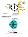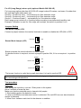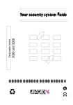
1
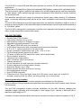
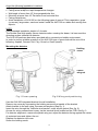
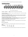
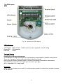
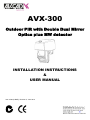
AVX-300 Outdoor PIR with Double Dual Mirror Optics plus MW detector INSTALLATION INSTRUCTIONS & USER MANUAL Item 4786 (A4BKE), Revision II, June 2012 The AVX-300 is unique PIR and Microwave detector for outdoor (IP-66) and harsh environment applications. It comprises of Double Mirror Optics and advanced MW Detector inside stylist rigid plastic body. This special mirror optics combined with state of the art MW Doppler sensor assures elimination of “false alarms” while maintaining high security standards for the detection of human intruders into protected area. The detection sensitivity and range is controlled by digital rotary switch allowing 16 calibration levels, so that the effective pattern will be set for every installation environment and protection site. The AVX-300 is designed to protect large areas and can easily be installed on walls in order to provide a solid protection of the area while rejects interferences from birds and small animals due to “Pet Mask” optics. The AVX-300 is designed for continuous round-the-clock operation and keeps its performances within a wide temperature and humidity range. AVX-300 FEATURES Double Dual PYRO sensor Full pattern double mirror optics MW detection based on Doppler concept Adjusted horizontally between 0° and 180° FET based DRO with strip line antenna VLSI based electronics with movement speed spectrum analysis N.O. & N. C. relays switched at the same time Height installation calibrations free, from 1.5m to 3.0m Pet and small animal Immunity up 40kg 16 levels of MW and PIR sensitivity rotary switch adjustment Environmental immunity Temperature compensation Micro controller signal processing Tamper protection Sound indication for walk test and intruder detection Unique waterproof and seal plastic design Detection Range: Up to 20m Detect human intruders walking or running No maintenance required High RFI/EMI Immunity Protection from: Direct sunlight, wind up to 30 m/sec, snow and rain, small Pet animals, removing the top cover, housing pulling out or destruction Selecting mounting location The installation of the AVX-300 requires straight and solid base for the detector. Local conditions of the protected zone better free from obstacles like walls, fences, trees, ditches, RF microwave. The AVX-300 intergraded bracket provides installation on the wall, allowing changing the installation angle (vertically and horizontally) in wide range (Fig.2), choose a wall level with a maximum slope angle of 10°. Consider a location that most likely intercept an intruder according to detection pattern in Fig. 6. 2 Avoid the following Installation Locations: Facing direct sunlight. Facing areas subject to rapid temperature changes. Wall angle of more than 10º from perpendicular line. Mounting at more than 10º Deviation from horizontal line. Facing metal doors. Avoid installation of AVX-300 on the following types of ground: Thick vegetation, grass (un-mown), large water, sand and metal. Install the AVX-300 on stable and moving-free objects. NOTE: Recommended installation height is 2.4 meter. The Double Dual high quality sensor detects motion crossing the beam; it is less sensitive detecting motion towards the detector. The AVX-300 performs best when provided with a constant and stable environment. In order to ensure suitable operation of the AVX-300 type of ground should be one of the following: Asphalt, Cement, Soil, Clay, Gravel or Grass (mown). Mounting the detector Holding screw Plastic wing nut Fig.1 Cover opening Fig.2 W iring and positioning Use the AVX-300 integrated bracket for wall installation. Remove top cover by unscrewing the holding screw at the topside of the bracket. Attach bracket to the wall using 4 screws and anchors (See fig. 1). Insert the wire through the “line/hole wire bracket” under silicon gasket (See fig. 2). Access for wiring connections is easy via the terminal block located on the PCB. See fig. 3. For detector alignment, unscrew the plastic wing nut, adjust the detector facing against the center of protected area and tighten the nut. Replace the detector top cover. Screw the holding screw. 3 For pole and post installations consider adding a proper adaptor (not supplied) Terminal Block Connections - 12V + EOL NC C NO EOL TAMPER EOL 1 2 3 4 5 6 7 8 9 10 Fig.3. W iring connections Terminal 1 – Marked “ – ” (GND) – Connect to the ground of the control panel. Terminal 2 – Marked “ + ” (+12V) – Connect to a positive Voltage of 8.2 –16Vdc source (usually from the alarm control unit) Terminals 4, 5 & 6 – Marked “NC C NO” - These are the output relay contacts of the detector. Connect to a normally closed or normally opened zone in the control unit. When an intruder is detected, alarm relay (N.O. and N.C.) switch for 1.8 sec. Terminals 8 & 9 – Marked “Tamper” – If a Tamper function is required connect these Terminals to a 24-hour normally closed protective zone in the control unit. If the top cover of the detector is opened or the detector is detached from installation wall, an immediate alarm signal will be sent to the control unit. Terminals 3, 7 & 10 – Marked “EOL”- End of line – optional terminals for end of line resistors connections. Wire size requirements Use #22 AWG or larger wires. Use the following table to determine required wire gauge and length. Wire Gauge: # 22 20 18 16 Wire Length: m 205 310 510 870 Ft. 800 1200 2000 3400 For wires that placed under ground, at high humidity areas and similar use NYY special wires. 4 Top PCB Layout Fig. 4: Interface PCB layout LED Indicators Yellow LED - MW detection, is blinking during warm up period and self testing Green LED - PIR detection Red LED - Alarm Test and Tuning Sensitivity and Range Adjustment The calibration of range and sensitivity is performed by single digital 16 position rotary switch. There are 3 groups of switch setting according to detection range. Each group is divided to several levels of sensitivity according to installation environment. The sensitivity levels values changed upon the mirror optic type. WA = wide angle. LR = Long range Important: Make walk test at least once a week, to confirm proper operation, cause alarm trig and coverage of the detector. 5 WA Low Risk Noisy Area Very High Risk High Risk LR High Risk 15 Low Risk m Risk Low Risk F 0 7 m 21 High Risk m 1 E 2 D Very High Risk 3 Noisy Area C 4 B 40 Low Risk m High Risk Risk WA LR Extremely Noisy Area 5 A WA 6 9 8 7 Low Risk Risk 15 m High Risk LR 28 Low Risk m High Risk Very High Risk Installation Hight: 3m Bracket Angle: 0° Noisy Area Fig. 5: Rotary switch setting For WA (Wide Angle) mirror optic The WA version is covering 18 meters range and 90° at temperature of 21° C. As the temperature rise the sensitivity is decreasing. Fig. 6: W ide Angel (W A) PIR + MW Detection Pattern 6 For LR (Long Range) mirror optic (optional Model AVX-300-LR) For long-range optics order item AVX-300-LR, range is about 20 meters, one beam. Consider that this type has higher false alarm rate. Group A - Positions 0 and 1 – set sensitivity for 40m detection range Group B - Positions 6 and 7 – set sensitivity for 28m detection range Group C - Positions B and C – set sensitivity for 15m detection range Each range group includes 5 or 6 setting levels according to environmental condition risk. Example: If detector is used for 15m range with sunlight, set switch to position 8 or 9. Jumpers Setting LED Mode Jumper (JP2) Connect a jumper between the marked terminals to enable or disable the LED (ON or OFF). OFF LED LED OFF Buzzer Mode Jumper (JP3) ON OFF LED LED ON ON Buzzer provides the sound indication of Alarm signal. If a buzzer function is required, connect a jumper in position ON, if it is not required – in position OFF. BUZZER OFF Buzzer OFF ON BUZZER OFF Buzzer ON ON The buzzer function is useful during walk test when it is hard to see the LED. Important: Reset the detector from Control Panel or by powering down than powering up, before the new settings will take effect Test procedure Walk Test After tuning the sensitivity, connect 12Vdc power to the system. Allow 2 minutes of warm up time. Make sure that the protected area is cleared of all people. 1. Start walking across the detection zone. 2. Listen to ALARM sound whenever motion is detected (The red LED turns on also whenever motion is detected). 3. Allow 5 sec. between each test for the detector to stabilize. 7 Specifications Detection Method Double Dual Element PIR & MW Wide Range Mirror Pattern 90.5 with 30 zones detection X-Band: Microwave Frequency S-Band: 9.9 GHz 10.525 GHz 10.687 GHz 2.45 GHz Scope (Length of protection zone) Max. 21m (WA mirror). 40m (LR mirror) Power Supply Voltage 9.6 to 15 V filtered DC Current consumption Relay contacts values Start-up: 28mA ± 3mA Standby: 23mA ± 3mA Active: 20mA ± 3mA N.C 28Vdc 0.1 A with 10 Ohm protection resistors N.O 28Vdc 0.1 A with 10 Ohm protection resistors Warm up Period 120 Sec (Max.) Alarm Period 1.8 Sec (Max.) Tamper Switch N.C 28 Vdc Maximum current 0.1 A - open when cover is removed Detection Speed (Target velocity) 0.3 to 3 m/sec Dimensions of unit with bracket 192mm x 153mm x 251mm Gross Weight 0.57 Kg Operating temperature range -20C ~ +60C Protection Degree All openings with gasket and sealed Protection against water and dust IP-66 level RFI Protection 30V/m 10 – 1000 MHz EMI Protection 50,000V of electrical interference from lightning or power through Visible Light Protection Stable against halogen light, sunlight or reflecting light www.av-gad.com NOTE: Conduct Walk Test procedure at least once a week, to confirm proper operation and coverage of the detector. Consider sensitivity reduction at over 35° Celsius environment Warranty is according to Av-Gad “Detectors and Sensors Warranty” terms and manual. * Specifications are subject to change without prior notice. 8