1
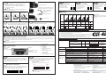
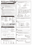
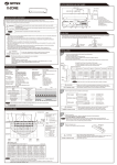
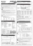
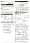
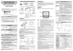
Attach the sensor with screws.
4
5
Plug the connector for the
sensor to that for the cable.
Apply power to the sensor. Then, adjust each detection area
(See ADJUSTMENT).
CAUTION
Make sure you connect the cable correctly to the
Door Controller before turning the power on.
MANUFACTURER’S STATEMENT
CAUTION NOTE ) prior to installing and adjusting the sensor system.
For ease of installation and proper operation read thru this manual (especially WARNING
Failure to read and follow the instructions in this manual may cause improper sensor operation resulting in serious injury or death.
This product is a non-contact activating switch intended for mounting on the header of an automatic door.
Do not use it for any other applications; otherwise proper operation and safety cannot be guaranteed.
Disregard of warning may cause the improper use causing death or serious injury of person.
WARNING
CAUTION
1.
2.
3.
4.
5.
6.
7.
8.
6
Disregard of warning may cause the improper use causing injury of person or damage to object.
NOTE
Special attention for the setting and adjustment of section of this symbol is required.
Set door speeds and verify proper operation of door manufacturer’s equipment prior to applying power to the sensor system.
Do not install the sensor where it might be directly sprayed with rainwater.
Verify proper wiring prior to applying power to the sensor system to prevent damage to equipment.
When setting the sensor’s area pattern, make sure there is no trafic around the installation site.
Do not attempt to rebuild or repair sensor heads or control unit. Contact an address in this manual for replacement products.
Only use the sensor as specified in the supplied instructions.
Walk test the installation to verify operation is in compliance with all local laws, codes and standards of your country.
Upon completion of installation and adjustments, instruct the owner/operator on proper operation of the door and sensor system.
Identify any switches/breakers that will place the door out of service when unsafe or improper operation is identified.
Model
Mounting Height
Detection Area
Detection Method
Detection Angle
Adjustments
Operation Indicator
Power Input
1. Slide the cover from right to
left onto the sensor.
Ԙ
3. Lock the cover with the Adjustment Hole Cap,
after installation and
ԙ
adjustment completely.
2. Press the cover firmly to the
sensor to attach.
ADJUSTMENT
Be sure to walk-test all of the detection areas.
When the Approach Angle and the Presence/
Motion Angle are set to 0qeach detection area
will be placed as shown on the right.
SPECIFICATIONS
: i-one
Current Draw
: 180mA Max. (AC12V)
: 2.1m (6'11") to 3.0m (9'10")
Output Contact
: "Form C" relay 50V 0.3A Max.
: See the chart in “ADJUSTMENT”.
(Resistance Load)
: Active Infrared Reflection
Relay Hold Time
: 0.5 to 2 sec.
(Presence DetectionType)
Response Time
: <0.3 sec.
: Approach Area ±15q(Inside & Outside)
Operating Temperature
: -26 C to +55 C (-15 F to +131 F)
Presence/Motion Area -8qto+5q(Inside & Outside)
Weight
: 400g (14oz.)
: Green : Stand-by
Accessories
: 1 Cable 3m(9'10")
Blinking Red : 1st Row Detection Active
2 Mounting Screws
Red : 2nd Row Detection Active
3 Adjusting Hole Cap
Orange : Motion Detection Active
1 Operation Manual
Blinking Orange : Approach Detection Active
1 Mounting Template
: 12 to 24V AC
The specifications herein are subject to change without prior notice due to improvements.
12 to 30V DC
*Mounting Height = 2.2m (7'3")
[mm (feet)]
[mm (feet)]
G
H
I
K
L
L
K
OUTER DIMENSIONS
123 (4 7/8")
127 (5")
66 (2 5/8")
304 (12")
70 (2 3/4")
5910364 Nov. 2010
3
Scale
1-1
Dipswitches
(1)
(2)
(3)
Mounting Holes
Connector
Approach Detection Unit
Dipswitches (Area Adjustment, Presence Timer,
Frequency, Rain Mode, Snow Mode, Detection Mode )
Operation Indicator
Presence/Motion Detection Unit
Sensitivity Potentiometers㧔Approach㧕
Sensitivity Potentiometers㧔Presence/Motion㧕
(4)
(6)
Scale
(1)
1-2
(7)
(5)
(8)
2
The width of the Approach Detection Area can be adjusted by
changing the Dipswitches as shown on the right.
7
1
8
8
2
7
3
5
4
3 to 6
7
8
7
8
4
5
4
5
2
7
3
6
Be sure to install the sensor where it will not be directly sprayed with rainwater.
1. Affix
x the Mounting Template to the mounting surface.
2. Drill two mounting holes ( ø 1/8" or 3.2mm).
3. To carry through the cable to the header, drill A ( ø 1/4" or 6mm).
4. After drilling the holes, remove the Mounting Template.
2 to 7
3
6
Active Area
the Presence/Motion
2 Adjusting
Detection Area
A
Sensor
Inactive
7
8
6
Inactive Area
Presence/Motion Area
Header
Door
WIRING
Remove the cover and pass the cable through B , then put the cable into A .
Dipswitches
NOTE
When you face difficulty in threading the cable through B ,
Presence/Motion Detection Unit
B
Width Adjustment
Shutter
1000(3'3")
Scale
Cable Knockout
2100(6'11")
3250(10'1")
4900(16'1")
Detection Area
B
12 to 24V AC
12 to 30V DC
B
Fine
Adjustment
Screw
F
Sensor
Mounting Surface
break off the cable knockout (as shown in the picture).
A
All Active
Approach Detection Area Width Adjustment
INSTALLATION
1
Adjusting the Area Depth
Adjust the depth of the Approach Detection Area
[mm (inch)]
Name of Parts
(5)
(6)
(7)
(8)
Approach Detection Unit
according to the traffic flow of the installed door
Operation Indicator
(1)
(2)
(3)
(4)
1 Adjusting the Approach Detection Area
[mm (feet)]
-8q
NOTE
Measure (B) is the distance from the Sensor
mounting surface to the edge of the Infra-red spot.
Distance to edge of Infra-red spot and actual point
of detection may vary.
B
F
-200 (-8")
0q
100 (4")
+5q
300 (12")
1380(4'6") 1450 (4'9") 1500 (4'11")
*Mounting Height = 2.2m (7'3")
2-1
Adjusting the Pattern Depth
3-4
Scale
Adjust the depth of the Presence/Motion Detection Area by
turning the Fine Adjustment Screw with a screwdriver.
The detection area of Presence/Motion Detection Unit can
Fine Adjustment Screw
be shifted closer to the door.
The depth of the Presence/Motion pattern can
Set this switch to Rain
if the sensor is used in
a region with a lot of rain.
Make sure the detection area do not overlap with the door,
When you finish installing,
insert the Adjustment
otherwise ghosting may occur.
Pattern When Changed 5q Pattern When Changed 8q
to Inside (Shallow)
to Outside (Deep)
Hole Cap
(to prevent tampering).
3-6
Setting the Snow Mode
Normal
Rain
5
5
Set this switch to Snow
if the sensor is used in
a region with snow or
a lot of insects.
be fine-tuned even when the cover is attached.
CAUTION
Standard Conditions
3-5
Setting the Rain Mode
Setting the Directional Mode
Normal
Snow
6
6
Multi
Uni
directional directional
11
11
4 Checking
Check the entry motion according to the following chart.
Entry motion
Outside the
Detection Area
Entry into the
Approach
Detection Area
Entry into the
Motion
Detection Area
Entry into the
2nd row of Presence
Detection Area
Entry into the
1st row of Presence
Detection Area
CAUTION
Outside the
Detection Area
Power off
Adjustment Hole Cap
Setting to Unidirectional
allows the door to close
more quickly
for departing trafic.
The response time may differ according to
the color of the objects and the color/material
of the floor.
(Image)
Detection Angle: 0q Detection Angle: +5q Detection Angle: -8q
2-2
Adjusting the Rows
2-3
Adjusting the Pattern Width
Each side can be adjusted independently, allowing for asymmetrical
settings. Refer to the sticker between Width Adjustment Shutters.
Sensor Status
Rows can be eliminated to adjust pattern depth.
Operation
Indicator
Stand-by
Green
Output
contact
Opens
All Areas
Opens
All Areas
2 to 5
5 to 2
3 to 5
5 to 3
4,5
Approach
Detection
Active
Motion
Detection
Active
Blinking
Orange
Orange
Yellow
Green
White
Presence
Detection
Active
Presence
Detection
Active
Stand-by
Red
Blinking
Red
Green
Yellow
Green
White
Yellow
Green
White
Yellow
Green
White
5,4
Recommendations to building owner / operator
1 2 3 4 5 5 4 3 2 1
NOTE
1 2 3 4 5 5 4 3 2 1
1 2 3 4 5 5 4 3 2 1
1 2 3 4 5 5 4 3 2 1
FOR BETTER PRESENCE DETECTION AREA
1. After installing the sensor, put the cover on the sensor and turn the "Fine Adjustment Screw" Counterclockwise a minimum of 4 full turns(-8degrees).
This will adjust the detection area to the maximum negative angle.
2. In the case where this adjustment causes the door to cycle (Ghosting), turn the "Fine Adjustment Screw" Clockwise 1/4 turn and move out of the
detection area to test. Continue this process of 1/4 turn and test until cycling stops.
CAUTION
During this process, set the presence timer to 2 second re-learn time. Once detection area is properly adjusted, reset the presence timer to allow
for ANSI approved presence time.
3 Dipswitch Settings
3-2
Setting the Frequency Function
(Interference Prevention)
11:
Area Adjustment
Detection Mode
12:
Not Used (Future Development)
The sensor automatically adapts to environmental changes in the pattern,
if no movement is detected for the duration of the selected timer cycle.
First two rows from the door provide the presence detection.
(1) Select the presence detection time.
(2)Turn the power on.
(3) Do not enter the detection area for 10 seconds.
60 sec.
180 sec.
INFINITY
3
2
1
2
1
2
1
2
CAUTION
3
4
3
4
3
4
3
4
Orange/Red
(Blinking)
Slow Green Blinking
Hold the door open.
Orange/Red
(Blinking)
Do not operate.
Do not operate
consistently.
Operates by itself
(Ghosting).
Possible Cause
Solution
Use "2 sec." only for testing. Normal Presence Timer
is 60 sec. or longer.
Reference
Connection failure
Check the power supply.
WIRING
Floor cpndition was changed.
Turn the power off and on again.
Adjust to the stated voltage.
ADJUSTMENT1,2
Power Input is not adequate.
Connection failure
Dirty detection window
Check the wiring and the connector.
SPECIFICATIONS
WIRING
Clean the detection window.
ADJUSTMENT 5
There is a moving object in the detection area.
(ex. Plant, Poster etc.)
Remove the object.
ADJUSTMENT 1,2
There was an abrupt condition change in the detection area.
Check the installation conditions.
ADJUSTMENT 1,2
Another sensor's detection area is overlapping.
Waterdrops on detection window
Vibration of the header
The Presence/Motion Detection Area overlaps with the door.
Change the frequency setting.
ADJUSTMENT 3
Keep the detection window free from
waterdrops.
INSTALLATION 1
Secure the header.
Adjust sensor angle away from the door.
ADJUSTMENT 2-1
North and South American Subsidiary
OPTEX Technologies Inc.
3882 Del Amo Blvd., Suite 604 Torrance, CA 90503 U.S.A.
1
4
Green
Detecting while
Stand-by while
Warning Indication is On Warning Indication is On
Corporate Headquarters
Four different frequencies can be set by adjusting Dipswitches 3 and 4.
When two or more sensors are mounted close to each other, they
may interfere. When that happens, change Frequency .
2
Detection
If the trouble still persists after checking and remedying as described above, contact your installer or the sales engineer.
9,10: Presence/Motion Detection
TEST
Stand-by
Signal Saturation
Setting the Presence Timer
*2 sec.
Sensor Status
Mode
Problem
7,8: Approach Detection Area
Adjustment
Presence/Motion Sensitivity
Potentiometer
(Factory setting : Midpoint)
Setting the Sensitivity
1
Warning Indication
Either the mounting position is too low or the
detection area includes the wall or another.
3,4: Frequency
5:
Rain Mode
6:
Snow Mode
Dipswitches
Both theApproach Sensitivity Potentiometer and the Presence/
Motion Sensitivity Potentiometer are factory-set at the midpoint.
Turning them clockwise increases the sensitivity and turning
counterclockwise lowers the sensitivity.
3-3
TROUBLESHOOTING
1,2: Presence Timer
Approach Sensitivity
Potentiometer
(Factory setting : Midpoint)
3-1
1. Do not change the settings on the sensor, as this may cause it to operate incorrectly.
2. Contact your local distributor if you want to change the settings.
3. Do not wash the sensor with water.
4. Always keep the detection window clean. If dirty, wipe the window lightly with a damp cloth.
5. Do not disassemble, rebuild or repair the sensor yourself; otherwise electric shock may occur.
6. If a Warning Indicator appears (LED warning), contact your local distributor.
7. When turning the power on, always walk-test the sensor pattern to ensure proper operation.
TOLL-FREE: 800 877 6656 FAX.: +1 310 214 8655
WEBSITE: www.optextechnologies.com
East Coast Office
8510 McAlpines Park Drive, Suite 108 Charlotte,
NC 28211 U.S.A.
TOLL-FREE: 800 877 6656 FAX.: +1 704 365 0818
WEBSITE: www.optextechnologies.com
European Subsidiary
Manufacturer
OPTEX Technologies B.V.
OPTEX CO.,LTD.
Tiber 2, 2491 DH The Hague, The Netherlands
TEL.: +31(0)70 419 41 00 FAX.: +31(0)70 317 73 21
E-MAIL: [email protected]
WEBSITE: www.optex.nl
5-8-12 Ogoto Otsu 520-0101, Japan
TEL.: +81(0)77 579 8700
FAX.: +81(0)77 579 7030
WEBSITE: www.optex.co.jp