1
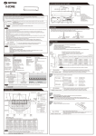
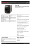
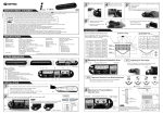
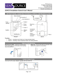
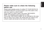
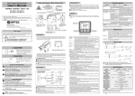
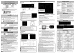
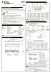
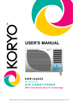
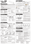
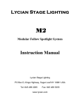
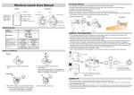
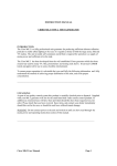
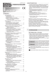
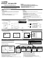
Prowave Air-wave RX
FEATURES
・Identifies zone (location) by 3 LED lights (3 zones + 1 continuous zone).
・Able to learn 12 transmission codes (Each zone can learn 3 transmitters maximum).
・Automatic “Learning” function facilitates to preset transmission codes to Air-wave RX.
・Over 8 million codes possible, eliminates interference from neighbors.
・Latches into alarm with “Continuous mode” function.
・Adjustable duration for terminal output.
・Low battery indicator to recognize transmission units’ battery status.
SINGLE RELAY RECEIVER (RG-10U)
Air-wave RX INSTALLATION INSTRUCTIONS
Please read this manual carefully before installation.
1 CAUTION AND WARNING
WARNING
1. Harsh environments
Using the Air-wave outdoors in severe conditions such as extreme temperatures,
rapid temperature change, high humidity, steam or fog may cause malfunction.
CAUTION
1. Impact/Shock
Impact or Shock can cause severe damage or break the Air-wave RX.
2. Electric Devices
Use Air-wave RX at least 3ft (1m) away from electronic devices such as TVs, Radios, PCs,
Microwave ovens. This may cause the unit to malfunction.
3. Transmission range
Transmission range may decrease under the following conditions:
- Either transmission units or Air-wave RX installed on a metal surface.
- Presence of a steel door, reinforced concrete or other metal obstructions between
transmission units and Air-wave RX.
- Places near strong radio sources such as broadcast stations or substation.
4. Cleaning
Harsh cleaners such as paint removers or benzene may ruin the surface. Use a soft wet
cloth and mild soap to clean.
2. Tampering
Any changes or modifications not expressly approved by OPTEX could void
the user's authority to operate the equipment
(see FCC note in section 13 COMPLIANCE of this manual).
3 TRANSMISSION RANGE (REFERENCE)
2 PARTS IDENTIFICATION
Function
Zone indicator 1
Zone indicator 2
Switch 1 Activating “Learn Mode” and
“Output Duration Mode”
Switch 2 Making selection
Zone indicator 3
Transmission range must be changed according to environment.
Please check if system works properly for the site.
Switch 1
Power
indicator
Power
Switch
Switch 2
Mounting
hole
Connection
terminal
cover
Output
connection
terminal
FRONT
Stand
BACK
Note: When you recycle this product, please disassemble product and recycle according to state law.
Sensor unit
Air-wave TX
1000ft (Open field, line of sight)
150ft (Stucco/Plaster construction)
100ft (Concrete construction)
Button unit
TS-10U
700ft (Open field, line of sight)
110ft (Stucco/Plaster construction)
70ft (Concrete construction)
Receiver
Air-wave RX
Mounting screw
4 INSTALLATION
Wiring
How to connect the Terminal
Use a power source
within the following range; 12~24V AC/DC
Door controller
POWER
12 - 24 V AC/DC
COM
ACTIVATE
Remove the connection terminal cover
Remove knockouts according to wiring needs.
When using for door controller,
connect NO and COM to activate input.
Usually the activate input is NO.
5 TEACH TRANSMITTER CODES TO Air-wave RX “LEARN MODE”
Each transmitter has a unique transmission code, which
can be automatically “learned” by the Air-wave RX. The
Air-wave RX’s zones must be taught to respond to the
appropriate transmitter. The zone characteristics can be
programmed as shown below.
Zone 1:
Zone 2:
Zone 3:
Zone 4:
Teach the transmitter code to the receiver
Activate the transmitter you wish to teach the receiver.
Activate “LEARN” Mode
A) The Air-wave RX
automatically starts in
“Learn” mode if no
transmitter code has been
programmed.
OR
B) Press and hold Switch 1
until the power indicator
starts to flash.
Timed utility output
Timed utility output
Timed utility output
Continuous terminal output
(latches until Switch 2 is pressed to deactivate)
The corresponding zone indicator flashes N times rapidly at intervals of 1 sec
according to the N number of transmitters, N=Maximum 3.
Zone 1
Receiver starts
in Zone 1.
Note:
• Revert to normal operation status before use.
• Verify that each transmitter has been learned by the receiver by triggering them.
• Each zone can accept a maximum of 3 transmitters, and the zone indicator shows the activated
transmitter based on the number of flashes.
(e.g. If transmitter 2 in zone 1 is activated, the zone 1 indicator flashes twice)
• A single transmitter cannot be learned by multiple zones.
• Turning off the devices, or losing power will not affect the transmitter or the Air-wave RX’s code memory.
Zone 2
Zone 3
Press Switch 2 to advance to the next zone.
Zone 4
Normal
Operation Status
Press Switch 2 to revert to
normal operation status.
Erasing Codes from the Air-wave RX’s Memory
1) Hold down switch 1 until the power indicator starts to flash.
2) Press Switch 2 until the appropriate zone indicator is lit.
3) Press Switch 1 to erase. The zone indicator will start to flash.
(Note: All programming in that particular zone will be erased.)
4) Press Switch 2 a few times until the power indicator stops flashing and remains lit.
Note: To erase all programming and revert to the factory default setting, turn on the
power while pressing and holding Switch 1.
6 ADJUSTING THE TERMINAL OUTPUT DURATION
• The terminal output duration can be set for zones 1-3 only as a
group. Zone 4 always latches until it is reset by pressing Switch 2.
• The factory setting is 1 sec.
After 5 seconds, the Air-wave RX will automatically revert to normal operational
status (the zone indicators will go off and the power indicator will remain lit).
Press Switch 2 to toggle through settings.
1 SEC.
5 SECS.
1
60 SECS.
30 SECS.
3
2
1
2
Normal
Operation Status
3
Press Switch 1 twice within 2 seconds to activate the
output duration mode (zone indicators display the
current setting).
8 LOW BATTERY INDICATION
7 INSTALLATION
FAN
Pull out the stand on the back of the
Air-wave RX and place it on any flat
surface.
Use the mounting screw on a wall. Leave
some length of the screw out for the
mounting hole of the Air-wave RX.
LONG
Desktop
Mounting On A Wall
Zone indicator on Air-wave RX and TX start slow flashing
whenever the corresponding transmitters have low battery.
Any operation cannot be done until one of operations below
below are conducted.
1) Replace transmitter’s batteries.
2) Press switch 2.
Air-wave RX will not need to relearn transmitter after
replacing the batteries.
Note: Check low battery status at the corresponding
transmitter in case several units are learned in 1 channel.
10 DIMENSIONS
9 TROUBLESHOOTING
1. The system is not operating
Check the transmitter.
Does the status indicator light up when
you trigger the transmitter?
Is the status indicator of the transmitter flashing?
Check to see whether the battery is inserted correctly.
If the battery is old, replace it with a new one.
The battery is old. Replace the battery.
Check the receiver.
Is the power indicator of the Air-wave RX lit ?
Have all the transmitter codes have been
taught correctly?
Are there other high power appliances using the
same electrical power outlet?
The zone indicator of the Air-wave RX is on, but
nothing happens.
Is the receiver on? Check the wiring and connection.
Teach the transmitter codes correctly. The system will
not operate without this process.
Is there anything blocking the transmission?
Please connect the Air-wave RX to a different electrical
outlet.
Check to see whether the terminal is properly
connected to other devices.
Relocate the receiver and/or the Air-wave RX. Metal
objects can shorten the effective transmission range.
Are the zone indicators flashing slowly?
Follow directions in 8 LOW BATTERY INDICATION.
2. The system is not operating correctly.
The Air-wave RX does not learn the transmitter
codes.
The Air-wave RX gets reception in the wrong zone.
The Air-wave RX does not respond to some of
the transmitters.
A certain zone seem to malfunction.
Before contacting the supplier!
Check whether the transmitter codes have already
been learned in a different zone. If so, erase the
memory and teach again.
Erase memory in the zone in which the Air-wave RX responds
and teach using the correct zone.
You may have taught multiple transmitter codes in
the same zone. Teach the transmitter codes for which
no response is received using an empty zone.
This is probably the transmitter’s problem. Check the transmitter
that corresponds to that zone.
Go through the setups again after turning on the
power while holding down switch 1.
• If the above solutions do not work, please contact your supplier for services.
12 COMPLIANCE
FCC ID : DC9RG-10U
The changes or modifications not expressly approved by the OPTEX could void the user’s authority to operate the equipment. To
comply with the FCC RF exposure compliance requirements, this device and its antenna must not be co-located or operating to
conjunction with any other antenna or transmitter.Note: This equipment has been tested and found to comply with the limits for a Class
B Digital Device, pursuant to part 15 of the FCC Rules. These limits are designed to provide reasonable protection against harmful
interference in a residential installation. This equipment generates, uses and can radiate radio frequency energy and, if not installed
and used in accordance with the instruction, may cause harmful interference to radio communication. However, there is no grantee that
interference will not occur in a particular installation. If this equipment does cause harmful interference to radio or television reception,
which can be determined by turning the equipment off and on, the user is encouraged to try to correct the interference by one or more
of the following measures.(1)Reorient or relocate the receiving antenna. (2)Increase the separation between the equipment and
receiver.(3)Connect the equipment into an outlet on a circuit different from that to which the receiver is connected.(4)Consult the dealer
or an experienced radio/TV technician for help.
Unit: inches (mm)
11 SPECIFICATION
Product Series
Product Name
Model Number
Power Source
Prowave Air-wave RX
Single Relay Receiver
RG-10U
12~24V AC/DC
Standby: 30mA
Operating: 80mA
Form “C” MAX 1A/50VAC DC24VAC
Relay Output
Selectable: 1/5/30/60sec
Output Timer
Power Indicator: Green
Status Indicator
Zone Indicator: Red × 3
Frequency
418MHz
Operating Temperature -10°C ~ +40°C
Installation Location Indoors
Weight
120g
Accessories
Mounting Screw × 1
Specifications may change without notice
13 WARRANTY
1. This product is warranted under normal use for 2 years from the Lot. number.
The Lot. number is printed on the sticker on back side of sensor. The first 2 digits stands
for year and the second 2 digits are week of manufacturing.
If you have questions, call to your sales representative.
2. The warranty is not applicable when below circumstances will be found:
• Mechanical or electrical modification(s) are made to the product or it is otherwise altered
manually.
• The product is already been serviced at place(s) other than the manufacturer.
• It is determined that the product malfunction has resulted from improper use or from an
accident. Physical damege will not be covered.
• No copy of the dated sales receipt has been submitted together with the product to be
serviced.
IC : CAN4012104524A
Operation is subject to the following two conditions.(1)this device may not cause interference, and (2) this device must accept any
interference, including interference that may cause undesired operation of the device.
To reduce potential radio interference to other users, the antenna type and its gain should be so chosen that the equivalent isotropically
radiated power (e.i.r.p.) is not more than that permitted for successful communication.
OPTEX Co.,LTD.
OPTEX Technologies Inc.
Corporate Headquarters
5-8-12 Ogoto Otsu 520-0101, Japan
TEL.: +81(0)77 579 8700
FAX.: +81(0)77 579 7030
WEBSITE: www.optex.co.jp
3882 Del Amo Blvd., Suite 604
Torrance, CA 90503 U.S.A.
TOLL-FREE: 800 877 6656
FAX.: +1 310 214 8655
WEBSITE: www.optextechnologies.com
East Coast Office
8510 McAlpines Park Drive, Suite 108
Charlotte, NC 28211 U.S.A.
TOLL-FREE: 800 877 6656
FAX.: +1 704 365 0818
WEBSITE: www.optextechnologies.com
2011.04 DRAFT 5918380