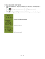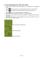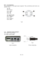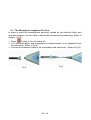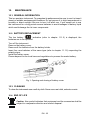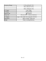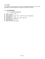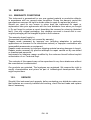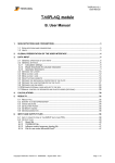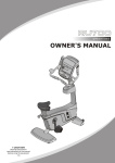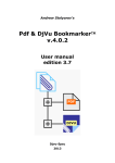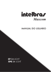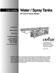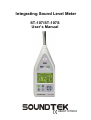
1
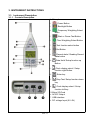
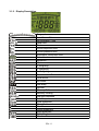
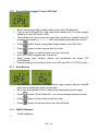
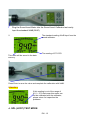
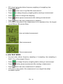
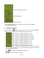
Integrating Sound Level Meter ST-107/ST-107S User’s Manual HB2ST1070003 Contents: 1. SAFETY PRECAUTIONS............................................................................................................ 3 1.1. Preliminary Description..........................................................................................................3 1.2. Note....................................................................................................................................... 3 2. PREPARATION FOR USE........................................................................................................... 4 2.1. Initial...................................................................................................................................... 4 2.2. Supply Voltage...................................................................................................................... 4 2.3. Calibration............................................................................................................................. 4 2.4. Storage.................................................................................................................................. 4 3. INSTRUMENT INSTRUCTIONS..................................................................................................5 3.1. Instrument Description...........................................................................................................5 3.1.1. Controls Description....................................................................................................................... 5 3.1.2. Display Description........................................................................................................................ 6 3.1.3. ST-109 Microphone........................................................................................................................ 7 3.1.4. ST-107S Microphone..................................................................................................................... 8 3.2. Measurement Procedures.....................................................................................................8 3.3. Data Hold.............................................................................................................................. 9 3.4. Maximum/Minimum...............................................................................................................9 3.5. Single Data Recode..............................................................................................................9 3.6. Viewing Logged Reading.......................................................................................................9 3.7. Set Mode............................................................................................................................. 10 3.7.1. Clock set ....................................................................10 3.7.2. Auto Recode Time Set................................................................................................................. 10 3.7.3. Auto Power Off Time Set............................................................................................................. 11 3.7.4. Clear Data Logger Memory .................................................................11 3.7.5. Clear All Data Logger Memory..................................................................................................... 11 3.7.6. Copy All Data Logger To micro SD Card.....................................................................................12 3.7.7. Auto Backup................................................................................................................................. 12 3.7.8. 94dB Calibration........................................................................................................................... 12 4. SPL (LXYP) TEST MODE.......................................................................................................... 13 5. LEQ TEST MODE...................................................................................................................... 14 5.1. integral Time set.................................................................................................................. 15 6. SEL (LAE) TEST MODE............................................................................................................ 17 7. PEAK MAXIMUM TEST MODE..................................................................................................18 8. RT60( REVERBERATION TIME) TEST MODE.........................................................................19 8.1. Rt 60 estimate mode........................................................................................................... 20 9. EXPLANATION.......................................................................................................................... 21 9.1. 1. Measurement Parameters:..............................................................................................21 9.2. A, C, Z Weighting Instruction:..............................................................................................22 9.2.1. Input interface ............................................................................................................................. 23 9.2.2. ANALOG AC/DC OUTPUT ......................................................................................................... 23 9.3. The Microphone Lengthens The Test..................................................................................24 10. MAINTENANCE....................................................................................................................... 25 10.1. General Information........................................................................................................... 25 10.2. Battery Replacement......................................................................................................... 25 10.3. Cleaning............................................................................................................................ 25 10.4. End of Life......................................................................................................................... 25 11. TECHNICAL SPECIFICATIONS..............................................................................................26 11.1. Feature.............................................................................................................................. 26 11.1.1. Standard:.................................................................................................................................... 28 11.1.2. General Data.............................................................................................................................. 28 11.2. Environment...................................................................................................................... 28 11.2.1. Environmental Conditions.......................................................................................................... 28 11.2.2. EMC........................................................................................................................................... 29 11.3. Accessories....................................................................................................................... 29 11.3.1. Standard Accessories................................................................................................................ 29 12. SERVICE................................................................................................................................. 30 12.1. Warranty Conditions.......................................................................................................... 30 12.2. Service.............................................................................................................................. 30 EN - 2 1. SAFETY PRECAUTIONS When taking measurements: ˙ Avoid doing measurements in humid or wet places - make sure that humidity is within the limits indicated in section “environmental conditions”. ˙ Avoid doing measurements in presence of explosive gas, combustible gas, steam or excessive dust. The following symbols are used: Caution: refer to the user’s manual. An incorrect use may damage the tester or its components The instrument conforms to the CE standard 1.1. Preliminary Description ST-109 is a high performance conforms to international IEC61672 Class 1 ST-107(S )is a high performance conforms to international IEC61672 Class 2 Integrating Sound Level Meter. It may also survey: SPL(Lxyp), Lxmax,Lxmin,,Lxeq, SEL (LAE),Lcpeak, RT60, , three kind of at the same time frequency weighting (A, C, Z) and three kind of at the same time weighting (F, S, I) may simultaneously survey many kinds of appraisal target, the dynamic range is bigger than 100dB, it does not need to select the measuring range when doing measurements, the operation is simple. Applications: Evaluation of environmental noise, Measurements of noise at workplaces, Assessment of product noise. 1.2. Note CAUTION Does not observe the warning and/or operation instruction, it’s possible to damage the instrument either its components or the operator ˙ Do not operate the instrument at temperature and humidity environment beyond to reference conditions of chapter 11.2.1. ˙ Keep the microphone dry and avoid severe vibration. ˙ Wind blowing across the microphone would bring additional extraneous noise. Once using the instrument in the presence of wind, it must mount the windscreen to prevent the undesirable signals. (Refer to Fig.1) EN - 3 2. PREPARATION FOR USE 2.1. Initial The instrument has been checked mechanically and electrically prior to shipment. Take care to ensure the instrument reaches you undamaged. However, it is wise to carry out a rapid check in order to detect any possible damage that may cause during transport. If its damage, claims to the dealer immediately. Check the packaging content according to packing list reported in 11.3.1chapter .In case of discrepancies, contact the dealer immediately. In the event of re-shipment of the instrument please follow the instructions reported in chapter. 2.2. Supply Voltage The instrument is powered by batteries. When batteries are low, a low battery indication is displayed. To replace/insert batteries as the instructions indicated in chapter. The instrument can also be powered by the external power supply. The external power supply’s voltage is 6~9V and its maximum output current is 500mA. CAUTION If you don’t use the instrument for a long period, please take the batteries out to prevent eventual acid leakage from damaging the instrument 2.3. Calibration The instrument complies with the technical specifications contained in this manual and such compliance is guaranteed for 1 year. The instrument is maybe need recalibration after one year. 2.4. Storage After a period of storage in extreme environmental conditions exceeding the limits mentioned in paragraph 11.2.1 let the instrument return to normal measuring conditions before using it. EN - 4 3. INSTRUMENT INSTRUCTIONS 3.1. Instrument Description 3.1.1. Controls Description 1. Microphone 2. : Power Button 3. : Backlight Button 4. : Frequency Weighting Select Butto 5. :Start or Pause Test Button 6. : Time Weighting Select Button 7. :Test function select button 8. :Set Button 9. :Record dada / Reading Record dada button 10. :Data Hold/ Setup function up Button. 11. :Clock display select / Setup function right Button. 12. 13. : Enter key :Stop Test/ Setup function down key. : Clock display select / Setup function left key. 15. Micro SD Card 16. AC/DC Output 17. USB interface 18. DC voltage Input (6V~9V) 14. EN - 5 3.1.2. Display Description Bargraph Auto Power Off Reverberation Time Data Hold Peak Sound exposure level Sound pressure level Equivalent continuous level Sound level read out Maximum Minimum Z Weighting C Weighting A Weighting Reverberation Time unit USB deliver SD Install Low Batty Recode Memory Full Memory Viewing Impulse Response Fast Response Slow Response Clock Read out t Start Measures Pause Measures Stop Measures Setup Mode Measure Time EN - 6 3.1.3. ST-109 Microphone ˙ ˙ ˙ ˙ Diameter : 1/2 inch Polarization voltage : 0V Dynamic range : 25dBA ~140dB Sensitivity : -26±2dB Free field frequency response : Frequency (KHz) 0.25 0.30 0.40 0.50 0.63 0.80 1.0 1.25 1.60 2.0 2.5 3.15 4.0 5.0 6.3 8.0 10 12.5 16.0 20.0 Deviation pressure 0 0 0 0.1 0.1 0.1 0.2 0.3 0.4 0.5 0.6 0.7 0.8 1.3 1.9 2.8 4.1 6.0 7.3 9.1 EN - 7 3.1.4. ˙ ˙ ˙ ˙ ˙ ST-107S Microphone Diameter : 1/2 inch Polarization voltage : 0V Dynamic range : 25dBA ~140dB Sensitivity : -32±3dB (250Hz 0dB=1V/Pa) Free field frequency response : ±2dB(25Hz~12.5kHz) Frequency (KHz) 0.25 1 2 3 4 5 6 7 8 9 10 12.5 3.2. Deviation of pressure 0.0 -0.1 -0.5 -0.6 -0.9 -1.2 -1.7 -2.2 -2.8 -3.3 -4.1 -6.0 Measurement Procedures Press button turn on sound level meter,press this button again turn off sound level meter Press ◎ Lxyp→Leq→LAE→PeakMAX→RT60 Press ◎ Fast→Slow→Impulse Press ◎ A weighting→C weighting→Z weighting Press Press button to select test function. button to select time weighting. button to select frequency weighting. button start test, press button again pause test button stop test Turn on the meter deform test mode is Lxyp mode; A weighting; Fast weighting EN - 8 CAUTION Wind blowing across the microphone would bring additional extraneous noise. Once using the instrument in the presence of wind with speed higher than 10m/s, it must mount the windscreen to prevent the undesirable signals. Keep the microphone dry and avoid severe vibration. Fig. 1 3.3. Data Hold ˙ Press button to lock display data, press this button again to unlock 3.4. Maximum/Minimum ˙ Press button to action MAX/MIN record mode, store maximum/minimum data, store time 99hours 59 minutes 59seconds,can press measure action in advance button end 3.5. Single Data Recode ˙ Press button each time to store the display reading and memory location in memory。 3.6. Viewing Logged Reading ˙ Press ˙ Press button more than 1 sec into the viewing logged reading mode or button to scroll through the readings EN - 9 ˙ Press ˙ Press or button to change time data (hh:mm:sec→YY-MM-DD) button again to exit viewing logged reading mode 3.7. Set Mode ˙ Press 3.7.1. button into set mode , can set 7 functions in set mode Clock set ˙ Press or button to select option to adjust ˙ Press or button to change digit ˙ Press button to store set and exit set mode ˙ Press button no store set data, into next set mode 3.7.2. Auto Recode Time Set ˙ Press or ˙ Press or ˙ Press button to select option to adjust button to change digit button to store set and exit set mode ˙ Press button no store set data, into next set mode ˙ Minimum auto recode time: 1 second; Maximum auto recode time: 23 hours 59 minutes 59 seconds ˙ Set auto recode time equal 0 second0 disable auto recode function EN - 10 3.7.3. Auto Power Off Time Set ˙ Press ˙ Press or button to change digit button to store set and exit set mode ˙ Press button no store set data, into next set mode ˙ If you want to not auto power off, you can set auto power off time to 0 ˙ Maximum auto power off time: 99 minutes 3.7.4. Clear Data Logger Memory ˙ Press button to clear data logger memory for last record ˙ Press button to store set and exit set mode ˙ Press button no store set data, into next set mode 3.7.5. Clear All Data Logger Memory ˙ Press button LCD will flash “ALL” ˙ Press button again clear all data logger ˙ Press button to store set and exit set mode ˙ Press button no store set data, into next set mode EN - 11 3.7.6. Copy All Data Logger To micro SD Card ˙ Before carrying on data to copy please insert micro SD card first ˙ Copy to micro SD card file to be named this machine ID; The max support capacity of micro SD card is 4GB ˙ This machine ID can be gone to by the user to define by oneself in the PC program, file format is ○○○○○○○○.IAR; Can define word dollar as 0~9;A~F ˙ Press button Starts copying data logger data to micro SD Card ˙ Press button to store set and exit set mode ˙ Press button no store set data, into next set mode ˙ micro SD CARD suggests use Transcend ˙ When usage copy function, please use transformer the power (DC 6~9V/500mA) ˙ Please change into the format of the micro SD card FAT or FAT32 formats 3.7.7. Auto Backup ˙ The auto backup function is automatically copy memory data into miniSD card, and automatically delete record data ˙ Be in use auto backup function, please use transformer power supply ˙ Press button LCD will flash”On”, be in use automatic backup function ˙ Press button to store set and exit set mode ˙ Press button no store set data, into next set mode 3.7.8. 94dB Calibration 94 dB calibration: 1. EN - 12 Plug the Sound Level Meter into the Sound Level Calibrator test cavity. Input the standard 94dB(1KHZ). The standard reading 94 dB input from the sound calibrator. 2. The reading of ST-107S. This value will be saved in the data memory. 3. Press Enter to save the value and complete the calibration with 94dB. REMARKS: If this reading is out of the range of 91.0 ~ 97.0 that mean this meter can not be calibrated with the calibrator; please return for inspection the problems. 4. SPL (LXYP) TEST MODE EN - 13 • SPL (Lxyp) test mode deform frequency weighting is A weighting; time weighting is FAST. • Press button start a Lxyp Max/Min measurement. • Press to change frequency weighting before starting a measurement . • Press button to change time weighting . • Press • • Press button can end a measurement in advance. LCD show on the period of the measurement is for experience time, the longest record 99hours 59 minutes 59sec. button pause measurement after starting a measurement Have not started measurement Start measurement Pause measurement 5. LEQ TEST MODE • Leq test mode deform frequency weighting is A weighting; time weighting is FAST; Time of the integral 30 secs. • Press to change frequency weighting before starting a measurement. • Press button pause measurement after starting a measurement. • • Press button can end a measurement in advance. LCD show on the period of the measurement is an integral time,adopt countdown system . EN - 14 Have not started measurement Start measurement End measurement ※ LEQ Auto Record Setting: in LEQ measurement time setting toggle by 'RECORD/MEMORY' key 5.1. INTEGRAL TIME SET Leq test mode press button into integral to set for time, can select that 9 kinds of integral time or hand operation establish definite integral for time . • SET 0 prepare to establish integral time 10 sec • SET 1 prepare to establish integral time 1 minutes • SET 2 prepare to establish integral time 5 minutes • SET 3 prepare to establish integral time 10 minutes • SET 4 prepare to establish integral time 30 minutes • SET 5 prepare to establish integral time 1 hour • SET 6 prepare to establish integral time 8 hour • • • • • SET 7 prepare to establish integral time 16 hour SET 8 prepare to establish integral time 24 hour SET 9 moveses to establish definite integral for time, the shortest integral calculus time 1 sec, the longest integral calculus time 30 days 23 hours 59 minutes 59 sec Press ; button choose integral calculus enactment. button to select option to adjust. EN - 15 • • ; Press button to change digit. button to store set and exit set mode. EN - 16 6. SEL (LAE) TEST MODE • SEL (LAE) test mode deform frequency weighting is A weighting;time weighting is FAST. • Press to change frequency weighting before starting a measurement • Press button pause measurement after starting a measurement. • • Press button can end a measurement in advance. LCD to show on the period of the measurement is for experience time,the longest record 99hours 59 minutes 59sec Have not started measurement Start measurement End measurement EN - 17 7. PEAK MAXIMUM TEST MODE • Peak test mode deform frequency weighting is C weighting; time weighting is Peak. • Press • • Press button can end a measurement in advance. LCD show on the period of the measurement is for experience time,the longest record 99hours 59 minutes 59sec. button pause measurement after starting a measurement. Have not started measurement Start measurement End measurement EN - 18 8. RT60( REVERBERATION TIME) TEST MODE • RT60 test mode deform frequency weighting is A weighting; time weighting is Fast. • Press to change frequency weighting before starting a measurement. • Press button pause measurement after starting a measurement. • Press button can end a measurement in advance. MAX value is the 1st getting value equal / or more than 90dB. MIN value is MAX value minus 60 dB, the 60dB is a fixed/standard value after calculation. The reverberation time is for calculating the require time from MAX. value (i.e. 91dB) reduce to MIN (i.e.31dB) . • • • Have not started measurement Start measurement End measurement EN - 19 8.1. RT 60 ESTIMATE MODE • RT 60 estimate formula is RT60=(0.161×V)/SA • Press 10 • • Press button for setting the value of sound surface absorb accumulates value (SA), for Example : 1.0 . • Press button for RT60 estimation, for example : 1.6 seconds • Press button to exit RT 60 estimate mode. • ; button are for the input value modification (more or less) for room m3 or SA if necessary. button for setting / input the room’s m3 (cube meter), for example: EN - 20 9. EXPLANATION 9.1. 1. MEASUREMENT PARAMETERS: Test Function Screen parameter Explanation SPL LAFp Sound pressure level (SPL) SPL LASp Sound pressure level (SPL) SPL LCFp Sound pressure level (SPL) SPL LCSp Sound pressure level (SPL) SPL LZFp Sound pressure level (SPL) SPL LZSp Leq LAFq Sound pressure level (SPL) Equivalent continuous level for the duration of the measurement for A weighting LCFq Equivalent continuous level for the duration of the measurement for C weighting LZFq Equivalent continuous level for the duration of the measurement for Z weighting SEL LAE Frequency weighted sound exposure level for the duration of the measuremen for A weighting SEL LCE Frequency weighted sound exposure level for the duration of the measuremen for C weighting SEL LZE Frequency weighted sound exposure level for the duration of the measuremen for A weighting Peak Lcpeak Leq Leq Instantaneous C peak level EN - 21 9.2. A, C, Z WEIGHTING INSTRUCTION: A: The A weighting curve is based on 40 Phon Fletcher-Munson Equal Loudness Contour, Noise assessment in human, suggest to use the A weighting. C: The C weighting in essentially is approximate smooth. With labor safety concern, suggest using the C weighting. Z: The Z weighting for the electric instrument interior not the linear signal which processes after the filter, suits in wants to output AC or the DC signal does other research to use. The Z weighting is a linear signal which is not processed through the filter. It’s suitable to output AC or DC signal for research. 3. Sound Level Meter Class Description: Class 0: use in the laboratory reference standard. Class 1: laboratory or field use. Class 2: laboratory or field use. Class 3: general field use. EN - 22 9.2.1. Input interface The front is PLT 4, the signal input receptacle. The pin definition and function are shown in Fig 2︰ ST-107 Pin 1 Power Pin 2 GND Pin 3 NC Pin 4 NC ST-109/ST-107S Pin 1 Power(+) Pin 2 GND Pin 3 Power(-) Pin 4 GND Fig 2 ANALOG AC/DC OUTPUT AC output:2 Vrms/130dB DC output: 2Vdc/130dB 9.2.2. Fig 3 Fig 4 output receptacle 3.5mm output plug EN - 23 9.3. The Microphone Lengthens The Test In order to avoid the measurement deviation caused by the reflection effect and operation problem, use the cable to extend the microphone for measuring. (Refer to chapter 11.3.2). 1. Press button to turn the power off. 2. Turn the preamplifier and microphone counterclockwise to be separated from the main body. (Refer to Fig 5). 3. Connect the extension cable to the microphone and main body. (Refer to Fig 6). Fig 6 Fig 5 EN - 24 10. MAINTENANCE 10.1. GENERAL INFORMATION This is a precision instrument. To guarantee its performances be sure to use it or keep it stored on suitable environmental conditions. Do not expose it to high temperatures or humidity or direct sunlight. Be sure to turn it off after use. If you expect not to use the instrument for a long period remove batteries to avoid leakages of battery liquid which could damage the its inner components. 10.2. BATTERY REPLACEMENT The low battery “ ” indication (refer to chapter 11.1.2) is displayed, the batteries are to be replaced. Turn off the instrument. Remove the battery cover. Remove all the batteries from the battery holder. Insert four new batteries of the same type (refer to chapter 11.1.2) respecting the polarity signs. Install the battery cover. Please depend on the local laws and regulations to process the waste battery. Fig 1: Opening and closing of battery cover 10.3. CLEANING To clean the instruments use a soft dry cloth. Never use a wet cloth, solvents or wate. 10.4. END OF LIFE Caution: this symbol indicates that equipment and its accessories shall be subject to a separate collection and correct disposal. EN - 25 11. TECHNICAL SPECIFICATIONS 11.1. FEATURE Environmental conditions: temperature 23℃ ± 5℃, relative humidity < 80%. Display Double rows LCD MAX reading 1999 Display Refresh Rate Major Standards Applicable 1 Time/sec IEC 61672-1:2002 Class1(ST-109) JJG-188-2002 Class 1(ST-109) IEC 61672-1:2002 Class2(ST-107/ST-107S) JJG-188-2002 Class 2(ST-107S) Other Standards IEC60651:1979 TYPE 1(ST-109) IEC60804:2000 TYPE 1(ST-109) ANSI S1.4:1983 Type1 (ST-109) IEC60651:1979 TYPE 2(ST-107/ST-107S) IEC60804:2000 TYPE 2(ST-107/ST-107S) ANSI S1.4:1983 Type12(ST-107/ST-107S) Microphone(ST-109) Microphone(ST-107S) 1/2” pre-polarized condenser microphone build in preamplifier: 50 mV/Pa, frequency range: 20 Hz~16 kHz, Thermal noise: <25 dB(A) 1/2” pre-polarized condenser microphone build in preamplifier: 1V/Pa@250HZ, frequency range: 20 Hz~12.5 kHz, Thermal noise: <25 dB(A) Microphone(ST-107) 1/2 inch Electret condenser microphone Measurement Items Lxyp, Lxmax, Lxmin, Lxeq, LAE, Lcpeak,RT60 Measurement Range 30dB to 130dB (A) 35dB to 130dB (C) 40dB to 130dB (Z) Dynamic Range Integrate Time Setup Internal memory Micro SD Card 100 dB Randomly, 10s, 1m, 5m, 10m , 30m, 1h, 8h, 16h, 24h 24C512 × 4 ;MAX Datalogger data >37,000 The max support capacity of micro SD card is 4GB; 37,000 data about story space 300KB Maximum Peak C Weighting Sound Level Measurement Time Weighting 70~133 dB Fast, Slow, Impulse, Peak Frequency Weighting A/C/Z EN - 26 Frequency Range 31.5Hz~8KHz(ST-107) 20Hz~8KHz(ST-107S) 20Hz~16KHz(ST-109) DC Output 2Vdc/130dB AC Output 2Vrms/130dB Starting Time <10 Second Battery Life 30 hours (LR6 : 4 Alkaline batteries) AC Adapter Input : 100V~240V ACV,Output:6V~9V DCV Dimensions 285(L) x 90(W) x 39(H) mm Weight 500g ( including Batteries) EN - 27 11.1.1. Standard: The instrument complies with IEC 61672 (2002) class 1; JJG-188-2002 Class 1;IEC60651:1979 TYPE 1, IEC60804:1985 TYPE 1, ANSI S1.4:1983 Type1.(ST109) The instrument complies with IEC 61672 (2002) class 2; JJG-188-2002 Class 2;IEC60651:1979 TYPE 2, IEC60804:1985 TYPE 2, ANSI S1.4:1983 Type2.(ST107) The instrument complies with IEC 61672 (2002) class 2; IEC60651:1979 TYPE 2, IEC60804:1985 TYPE 2, ANSI S1.4:1983 Type2.(ST-107) 11.1.2. General Data Mechanical characteristics Size: Weights (including batteries) : Power supply Battry type Low Battery : Battery life: 285(L) x 90(W) x 39(H) mm approximate 500g 4 batteries 1.5 V – LR6 – AA – AM3 – MN 1500 AC to DC Adapter. (6V~9V/500mA). Replace battery as LCD display “ ” About 30 hrs (alkaline Battery). 11.2. ENVIRONMENT ˙ ˙ ˙ ˙ ˙ ˙ 11.2.1. Environmental Conditions For inside use, max height: 2000m Reference temperature: 23° ± 5℃ Operation temperature: 5 ~ 40 ℃ Operation humidity: <80% RH Storage temperature -10 ~ 60 ℃ Storage humidity <70% EN - 28 11.2.2. EMC This instrument was designed in accordance with EMC Standards in force and its compatibility has been tested in accordance with EN61326-2 (2006). 11.3. ACCESSORIES 11.3.1. Standard Accessories Meter: Instrument body x 1 . User’s manual. Switching power supply: 100V ~ 240V AC to DC 6V~9V/500mA. Carrying case. 4 batteries 1.5 V – LR6 – AA – AM3 – MN 1500. 60mm diameter windscreen. Setup CD-Disk. MINI USB Cable (Mini B type). EN - 29 12. SERVICE 12.1. WARRANTY CONDITIONS This instrument is guaranteed for one year against material or production defects, in accordance with our general sales conditions. During the warranty period the manufacturer reserves the right to decide either to repair or replace the product. Should you need for any reason to return back the instrument for repair or replacement take prior agreements with the local distributor from whom you bought it. Do not forget to enclose a report describing the reasons for returning (detected fault). Use only original packaging. Any damage occurred in transit due to nonoriginal packaging will be charged anyhow to the customer. The warranty doesn’t apply to: Accessories and batteries (not covered by warranty) Repairs made necessary by improper use (including adaptation to particular applications not foreseen in the instructions manual) or improper combination with incompatible accessories or equipment. Repairs made necessary by improper shipping material causing damages in transit. Repairs made necessary by previous attempts for repair carried out by non-skilled or unauthorized personnel. Instruments for whatever reason modified by the customer himself without explicit authorization of our Technical Dept. The contents of this manual may not be reproduced in any form whatsoever without the manufacturer’s authorization. Our products are patented. The logotypes are registered. We reserve the right to modify characteristics and prices as part of technological developments which might require them. 12.2. SERVICE Shouldn’t the instrument work properly, before contacting your distributor make sure that batteries are correctly installed and working, check the test leads and replace them if necessary. EN - 30 TENMARS ELECTRONICS CO., LTD 6F, 586, RUI GUANG ROAD, NEIHU, TAIPEI 114, TAIWAN. E-mail: [email protected] http://www.tenmars.com