1
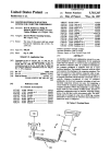
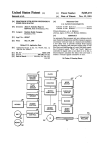
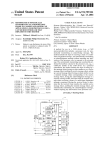
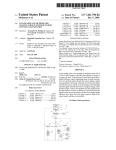
.
US005347113A
Ulllt?d States Patent [19]
[11] Patent Number:
Reddersen et al.
[45]
[54]
MULTIPLE-INTERFACE SELECTION
SYSTEM FOR COMPUTER PERIPHERALS
4,954,101
5,040,993
9/1990 Nelson .............................. .. 439/502
8/1991 Krug et a1.
..... .. 439/620
5,181,858
l/l993
[75]
Inventors: Brad R. Reddersen; Phllhp W.
Shepard; Rockie D. Moch, all of
_
_
Date of Patent:
5,347,113
Sep. 13, 1994
Matz et a1. ........................ .. 439/489
5,214,268 5/1993 Doing ................................ .. 235/462
5,222,164 6/1993 Bass, Sr. et a1.
439/488
Eugene, Oreg,
5,250,792 10/1993 Swartz et al. ..................... .. 235/472
[73] Assignee: Spectra-Physics Scanning Systems,
Inc., Eugene, Oreg.
[21] Appl. No.: 39,606
Primary Examiner-John Shepperd
Attorney, Agent, or Firm-Lyon & Lyon
[22] Filed;
An interface selection and con?guration system for a
Mar. 25, 1993
[57]
ABSTRACT
computer peripheral in which con?guration for the
Related US, Application Data
[63]
continuatiomimpm ofsen No_ 34,189, Man 22, 1993’
accomplished by ‘the interface connector cable. In a
which is a continuation of Ser. No. 788,267, Nov. 4,
1991, abandoned,
Preferred embodlment’ the computer Penpheral 1s
equipped with one or more hardware interfaces. The
interface connector cable has a ?rst end connector for
attaching to the computer peripheral_ The ?rst end
5
' '
[58]
peripheral and/or the host interface is at least in part
...................................
' """""""""""""""""""" " 439/489’_ 439/626
Field of Search
"""""
multiple pin connector constructed and arranged to be
/375 43g 465, 1741/268’
properly physically and electrically connectable only to
_
[56]
connector of the interface connector cable is typically a
439/488 489 ’491 620
’
’
’
a speci?c computer peripheral or class of computer
References Clted
peripherals, the ?rst end connector including at least
U.S, PATENT DOCUMENTS
4 579 407 M1986 Shimada
439/620
4:678:288 7/1987 Lonsdale
"""""" " 350/432
one electrical connection between two pins for com
pleting a circuit within the computer peripheral thereby
enabling the computer peripheral. Where the peripheral
4,694,182
is a data reading device Such as a laser scanner, alternate
9/1987 Howard ............................ .. 250/566
4,699,447 10/1987 Howard .
4,820,l93 4/1989 Noorily ............................. .. 439/488
or additional con?guration may be provided by read
ing, with data reading device, a label on the intercon
432??? 3/1939 5319“ et
nect cable. The label, which may for example be a bar
---- -~
--
16g
226837; 92383 B13323 '
23 51422
code, contains information or instructions by which the
4:902:244 2/1990 Endo et
439/439
data reading device (and/or the host) is con?gured.
4,915,639
4/1990
4,941,845
7/1990 Eppley et a1. ..................... .. 439/505
Cohn et a1.
. . ..
. . . .. 439/488
16 Claims, 5 Drawing Sheets
US. Patent
Sep. 13, 1994
Sheet 1 of s
'
5,347,113
US. Patent
Sep. 13, 1994
Sheet 2 of 5
5,347,113
21
22
[12.3
42
32
[12.1
US. Patent
Sep. 13, 1994
Sheet 3 of 5
5,347,113
US. Patent
Sep. 13, 1994
Sheet 4 of 5
5,347,113
US. Patent
Sep. 13, 1994
Sheet 5 of 5
5,347,113
1
5,347,113
SUMMARY OF THE INVENTION
MULTIPLE-INTERFACE SELECTION SYSTEM
FOR COMPUTER PERIPHERALS
The present invention relates to an interface selection
system for a computer peripheral in which con?gura
tion for the peripheral and/or its host is at least in part
accomplished through the interface connector cable. In
RELATED APPLICATIONS
This application is a continuation-in-part of applica
a preferred embodiment, the computer peripheral is
tion Ser. No. 08/034,189 ?led Mar. 22, 1993, which is a
continuation of application Ser. No. 07/788,267 ?led
Nov. 4, 1991 now abandoned.
2
equipped with one or more hardware interfaces. The
interface connector cable has a ?rst end connector for
10
attaching to the computer peripheral. The ?rst end
connector of the interface connector cable is typically a
BACKGROUND OF THE INVENTION
multiple contact connector (such as pin or edge connec
The ?eld of the present invention relates to intercon
tor) constructed and arranged to be properly physically
nection systems for computers and computer peripher
and electrically connectable only to a speci?c computer
peripheral (or class of computer peripherals), and a
speci?c host interface the cable connector including at
als or more speci?cally, methods and devices for select~
ing proper interface between a computer peripheral and
its host interface such as may include a computer.
Host computers need to be interconnected to a wide
least one electrical connection between two contacts
for completing a circuit within the computer peripheral
variety of peripheral devices including printers, scan
thereby enabling the computer peripheral.
ners, monitors, and controllers among others. When the 20 In another preferred embodiment where the periph
host computer is being connected to a certain type of
eral is a data reading device such as a laser scanner,
peripheral, for example a handheld laser scanner, the
alternate or additional con?guration may be provided
computer typically has a single input/output connector
by reading, with the data reading device, a label on the
to which the scanner may be connected by an intercon
interconnect cable. The label, which may for example
nect cable. It is frequently desirable that a particular 25 be a bar code, contains information or instructions by
handheld scanner be usable with a variety of different
which the data reading device (and/or the host) is con
?gured.
host computers. Conversely, it is also desirable that the
host computer be able to support a variety of different
BRIEF DESCRIPTION OF THE DRAWINGS
handheld scanners.
FIG. 1 is a diagrammatic view of a handheld laser
scanner attached to a host computer according to the
Heretofore there have been several systems for
achieving proper con?guration between the host com
puter and the peripheral. In a typical system, a particu
lar peripheral is con?gured to work with a particular
host computer, that is, the peripheral has contained a
single dedicated interface. Similarly, the host computer
present invention;
FIG. 2 is a diagrammatic view of an interface connec
tor system according to the present invention;
35
connector as in FIG. 2;
ent host computer, it was necessary to replace the inter
FIG. 5 is a diagrammatic view of an alternate periph
face software and hardware in the peripheral.
eral con?guration system;
The host computer may include a software selection
FIG. 6 is an end view of an end connector in FIG. 5
program in which the user inputs information identify
taken along line 6-—6;
ing the particular peripheral enabling the system to
FIG. 7 is an end view of an end connector in FIG. 5
have proper operation. Such an operation requires the
user to correctly input information into the host com
puter identifying the particular peripheral. Alternately,
taken along line 7—-7;
45
FIG. 5;
of the peripheral which informs the computer of the
host of the type of peripheral and software provides the
desired con?guration. Many of these systems still re
quire correct interface hardware.
FIG. 8 is a connector schematic illustrating an exam
ple cable connection scheme for the cable connector of
means are provided for scanning a code on the outside
type of peripheral. Some peripherals actually include
identifying signals which again inform the particular
FIG. 3 is a detailed diagrammatic view of a printed
circuit board of FIG. 2;
FIG. 4 is a detailed diagrammatic view of an edge
was con?gured to accept only a particular type of pe
ripheral. Any time the peripheral was moved to a differ
FIG. 9 is a diagrammatic view of an alternate periph
eral con?guration system;
50
'
FIG. 10 is an end view of an end connector in FIG.
9 taken along line 10—10;
FIG. 11 is an end view of an end connector in FIG.
9 taken along line 11-11;
In another con?guration technique, the peripheral
FIG. 12 is a connector schematic illustrating an exam
includes interface hardware for more than one host 55 ple cable connection scheme for the cable connector of
computer. When con?guring, the printed circuit board
of the peripheral requires certain hardware con?gura
FIG. 9;
tion in order to be correctly linked to a host computer.
bodiment;
FIG. 13 illustrates an alternate cable connection em
Such hardware con?guration may be effectuated by
FIG. 14 illustrates a cable scanning code operation;
manually actuable external switches or by internal 60 and
switches or “jumpers” within the printed circuit board
FIG. 15 illustrates various peripheral/host pairs.
(and/or within the host computer) which activate or
DESCRIPTION OF THE PREFERRED
deactivate certain components. Such an operation typi
EMBODIMENTS
cally requires the expertise of an electronics technician
or skilled user and is not a desirable ?eld operation to be 65
The preferred embodiments will now be described
performed by the typical user. It is desirable to have an
with reference to the drawings.
inexpensive and easy to use interconnection system
In FIG. 1, an example computer peripheral is illus
which can be effectively used by the average user.
trated as a handheld laser scanner 10 used for scanning
3
5,347,113
a bar code 11. The scanner 10 is operably connected to
a host interface (diagrammatically illustrated as a com
puter 15) via an interconnect cable 38. The interconnect
cable 38. includes an end plug or edge connector 30
4
contacts #2, #4 and #6 are used for communication.
When the interconnect cable 38 is plugged into the
printed circuit board 20, edge contacts #1 and #3 of the
edge connector 21 are thereby electrically connected,
which connects to a mating connector 21 on the end of 5 and edge contacts #5 and #7 are also electrically con
a printed circuit board 20 within the scanner 10. The
nected. By so electrically connecting these electrical
interconnect cable 38 provides a communication link
between the host computer 15 and the laser scanner 10
and may also provide power to the scanner 10.
Referring to FIG. 2, the interconnect cable 38 has a
?rst end connector 30 which plugs into the scanner 10
attaching to the edge connector 21 of the circuit board
20, and a second end connector 40 which plugs into the
host computer 15 attaching to the edge connector 18.
The ?rst end connector 30 includes tabs 34, 36 which
slide into and mate with corresponding slots 24, 26 in
the body of the handle of the scanner 10. Different types
of scanners may be equipped with different positions of
the slots 24, 26. Only an end connector 30 having the
correct con?guration of tabs 34, 36 will be correctly
physically connectable to the scanner 10. An intercon
nect cable 38 without the correct tab con?guration
cannot physically be plugged into the laser scanner 10.
Similarly on the host computer side of the intercon
nect cable 38, the second end connector 40 is equipped
with a tab 44 which mates with a corresponding slot 17
at the mating edge connector 18 of the host computer
15. Only an end connector 40 having the correct con?g
uration of the tab 44 will be correctly physically con
nectable to the host computer 15. An interconnect cable
38 without the correct tab con?guration cannot physi
callybe plugged into the host computer 10.
contacts, certain circuits within the circuit board 20
become electrically connected resulting in a desired
con?guration. The scanner 10 becomes con?gured to
accept a particular host computer 15. The user has
con?gured the scanner merely by plugging in the cor
rect interconnect cable 38.
A similar con?guration selection system may alter
nately or in combination be applied to the host com
puter connection side. The edge connector 40 has cer
tain of its edge contacts 42 electrically connected, in the
illustrated example pins #5 and #7 of the edge connec
tor 40 are jumped. When the edge connector 40 is
plugged into the edge connector 18 of host computer
15, edge contacts #5 and #7 within the edge connector
18 become electrically connected, completing a circuit
within the host computer 15, thereby con?guring the
host computer 15 for the particular peripheral. The user
may therefore con?gure the host computer 15 for the
particular scanner 10 by merely selecting and plugging
in the correct interconnect cable 38.
In practice, the user would be provided with a single
peripheral, such as a scanner and several interconnect
cables. To connect the scanner, the user would merely
select the interconnect cable corresponding to the par
ticular host computer and plug it into the scanner. The
interconnect cable would then con?gure the scanner for
Therefore in order to connect a particular peripheral
the particular host computer. To move the scanner to a
(such as a laser scanner 10) to a particular host com
different host computer, the user would merely have to
puter, a cable having the correct tab con?gurations at 35 switch cables. The interconnect cable 38 may be pro
both end connectors must be selected. The unique phys
vided with means for identifying such as identifying
ical con?gurations ensures that the user must select the
markings 39 imprinted directly on the interconnect
correct cable for the host computer and peripheral pair.
cable 38 itself, color coding, a label with identi?cation
The preferred embodiment may only require tab con?g
information connected to the cable 38, or the like to
uration on the host computer end because it is not antic 40 assist the user in selecting the correct interconnect cable
ipated that the various handheld scanners will require
the dedicated interconnect cables, but tab con?gura
for the given host.
tions on the peripheral end may be desired in other
simpli?ed example for a connector design. Electrical
peripheral applications. Further, the tab con?gurations
contact con?gurations may of course be more or less ,
The illustrated seven edge connector embodiment is a
illustrated are but one example means for ensuring 45 than seven contacts (and the two ends need not be the
proper interconnect cable selection. The tabs and slots
same). In a preferred scanner application, an intercon
are readily added to conventional end connectors. The
nect cable plug with 30 pins is set forth in Table A as
design illustrated does not prevent end connectors with
follows:
out tabs from connecting to the peripheral 10 and the
host computer 15, but such design may be modi?ed by
one skilled in the art (such as by reversing the positions
of the slots/tabs) to prevent such connection.
Referring to FIGS. 3 and 4, the printed circuit board
20 (located within the scanner 10) includes an edge
connector 21 shown with seven edge contacts 22 (num
bered 1 through 7). Though there is a distinction be
tween edge contacts and pins, for the purposes of the
present invention, they are interchangeable-a pin con
nector with its mating plug connector may be inter
changed for an edge connector pair or any other suit
able electrical contact pair.
The board 20 is designed and constructed to be opera
ble with a number of host computers by way of an
externally activated hardware con?guration provided
by the interconnect cable 38. As viewed in FIG. 4, in 65
the edge connector 30, the edge contacts #5 and #7 are
electrically connected, illustrated as being “jumped”.
Edge contacts #1 and #3 are also jumped while edge
TABLE A
Signal Name
TEST_.DATA
READ_DATA_WAND
START_DATA
CLOCKIN
CLOCKOUT
RDATA_RTN
SDATA_RTN
CLOCK_IN_RTN
CLOCK_OUT_RTN
VCC
VCC_OUT
VCC_IN
CLEAR__TO_SEND
TRANSMIT_DATA
RETURN_DATA
RETURN_S
DATA_._PLUS
DATA-MINUS
BEEP_IN
PWLEN
TRIGGER
Data Direction(s)
5
5,347,113
Pin #
22
23
24
25
26
27
28
29
30
Signal Name
Data Direction(s)
BALCODE_OUT
GOOD_READ_IN
START_OF__SCAN
MTLFAIL
GROUND
CONFIG__l
CONFIG_2
CONFIG__3
CONFIG_4
6
the desired electrical connection between the pins. The
interconnect cable 38 (or the printed circuit board 50
TABLE A-continued
thereon) may itself be equipped with dip switches 52
(dual inline package switches) or some other type of
switch. An interconnect cable equipped with switches
would have certain advantages as only one cable ver
10
sion need be manufactured. The cable type correspond
ing to a particular peripheral would be selected by set
ting the switches (by the manufacturer or by the skilled
user) and the cable could then stamped with an identify
ing code 39.
As described above, the handheld data reader or
The interconnect cable plug may use certain of the
pins for communication or power. Some of the pins may
be unused and available for other applications, it being
desirable that the same pin design be usable for different
con?gurations. The last four pins #27—#30 are dedi
other computer peripheral is generally connected by a
connector cable to a given host or interface. The host or
interface is typically a host computer such as a central
processing unit (CPU) or other intermediate device
which in turn communicates with the CPU. The host
cated for providing the con?guration for the peripheral.
The variations of con?gurations are limitless and may
be designed to suit a particular application. The exam
may be a communication module, such as an RF trans
mitter which is provides a radio frequency communica
ple in Table A is provided in part to show the wide 20 tion link to the host computer. In such an application,
variety of con?gurations that may be employed. By the
the cable is nonetheless connected to the host computer
cable con?guration scheme, the peripheral may be con
or CPU albeit through the communication module. If
?gured setting for example communication baud rate,
the peripheral is a printer for example, the host may be
bit setting (8-bit, 16-bit etc.), parity or some other pa
a network interface, into which the connector cable is
rameter.
Though particular types of end connectors have been
described, the pin connector may be any suitable electri
cal connector means for providing electrical contact
including plugs, pin connectors, sockets, edge connec
25
plugged, which is in turn connected to the host com
puter.
There are myriad of potential hosts for a given pe
ripheral. By way of another example, FIG. 13 illustrates
a system in which a handheld bar code scanner 210 is
tors and the like. The end connector has multiple
connected to a key entry terminal 230. The interconnect
contacts, the contacts providing the actual electrical
cable 220 has a ?rst end connector 222 plugged into the
contact surface. The contacts may be pins, edge
handheld bar code scanner 210. The second end con
contacts, plugs, sockets, or any suitable electrical
nector 224 is actually plugged into a translator module
contact element.
235 (sometimes called a “wedge”) which converts the
35
The center of the interconnect cable 38 may comprise
signal transmitted from the scanner 210 into a signal of
any suitable transmission medium including a wire (as
the same form as that produced by the key entry termi
illustrated), cable, ?ber optic cable, radio frequency
nal
230. The key entry terminal 230 is in turn connected
link, infra red light link, or other transmission medium.
by
a suitable communication link 237 to the central
The cable con?guration system described may be
combined with other con?guration systems, some of 40 processing unit 240. In this arrangement, the host is
literally the wedge 24 but may be also be considered to
which have been previously described. For example,
comprise a host assembly contained within the dashed
the interconnect cable system described herein may be
lined box and designated by numeral 250.
used to automatically select a con?guration for a certain
FIGS. 5-8 illustrate a preferred alternate embodi
class or group of peripherals. The peripheral may addi
ment
in which the peripheral is a handheld data reading
45
tionally include external (or internal) switches identify
ing the particular peripheral within the group thereby
completing the described con?guration.
device 110 such as a bar code laser scanner, a CCD
reader or other device. The scanner 110 is attached to a
In practice, a computer peripheral such as a laser
scanner 10 will be equipped with hardware and ?rm
host, diagrammatically illustrated as a data terminal 140,
by a connector cable 120 with a ?rst end connector 122
ware so that it may be used with a plurality of different 50 plugged into the scanner 110 and the second end con
nector 124 plugged into the data terminal 140. The
connector cable 120 is provided with a label 135 which
contains encoded data which may be read by the data
reader 110. The label 135 may, for example, be a sepa
55 rate tag on which the bar code is imprinted or the bar
code may be imprinted directly on the cable 120 itself.
As best shown in FIG. 6, the ?rst end connector 122
within the scanner 10, activating or deactivating certain
is illustrated as an edge connector having a plurality of
circuits, thereby con?guring the scanner 10 for the
host computers or computer terminals. To provide ini
tial con?guration or change con?guration when switch
ing host computers, the peripheral is con?gured merely
by selecting the correct interconnect cable 38. The
electrically connected pins in the end connector of the
interconnect cable provide the switching necessary
particular host computer.
edge contacts, including contacts 122a, 122b, for con
The interconnect cable 38 may be designed in any 60 nection into a corresponding connector in the handle of
suitable manner. In FIGS. 3 and 4 illustrate jump con
the scanner 110. FIGS. 5 and 7 illustrate the second end
nections between the respective edge contacts 32 of
connector 124 as a pin connector having a plurality of
edge connector 30 (or edge contacts 42 of edge connec
pins (including pins 124a, 124b) for connection into a
tor 40), other electrical connection mechanisms may be
corresponding connector in the data terminal 140.
employed. The contacts may be electrically connected 65 The cable 120 may also include an identi?cation label
by a simple hard wire connection. The interconnect
139 which has identi?cation information to assist the
cable 38 itself may include a printed circuit board 50,
user in selecting the correct cable for the particular
preferably in a unitary structure, which may provides
scanner and host pair. Other or alternate selection
7
5,347,113
8
tion is stored in a memory in the scanner so that repeti
means such as color coding may be provided to assist
the user in selecting the correct interconnect cable for
tive con?guration is not required. Typically, the bar
the particular application.
codes are contained in the user manual and the user
FIG. 8 schematically illustrates an example cable
connection scheme 150 for the cable connector 120 of
FIG. 5. Color coded cable wires (Brown, Orange,
Black, Yellow, Green, White) provide desired electrical
communication path between edge contacts (nos. 10, 9,
18 etc.) in the ?rst end connector 122 and respective pin
contacts (nos. 4, 3, 7 etc.) in the second end connector
124. The cable connector 120 also includes peripheral
con?guration selection by electrical connector 121
(connecting edge contacts 14 and 13) and by electrical
connector 123 (connecting edge contacts 1 and 17).
FIGS. 9-12 illustrate another preferred alternate
embodiment in which the peripheral is a handheld data
reading device 155 such as a bar code laser scanner, a
CCD reader or other device. The scanner 155 is at
tached to a host (diagrammatically illustrated as a data
must obtain the manual and then select the correct bar
code to be scanned. However, according to the pre
ferred embodiment shown in FIG. 14, the user 305 need
only select the correct interconnect cable 320 and the
correct bar code label 335 to be scanned is automati
cally selected since it is on the cable itself. Moreover,
being on the cable, the bar code is readily accessible and
locatable without having to locate the user manual.
Though once the system has been initially con?gured,
the system will preferably store the con?guration infor
mation, if it becomes necessary to recon?gure, the con
?guration bar code 335 remains readily accessible on
the cable 320.
Though the con?guring bar code conveniently ap
pears on the interconnect cable, con?guration bar codes
(i.e., the same bar code as appearing on the cable as well
as additional bar codes) may nonetheless be provided in
terminal 180) by a connector cable 160 with a ?rst end
the user manual to allow the user to con?gure the pe
connector 162 plugged into the scanner 155 and the
ripheral as desired such as to speci?c user optional set
second end connector 164 plugged into the data termi
tings.
nal 180. The connector cable 160 is provided with a
Con?guration on the basis of the encoded data in
label 175 which contains encoded data which may be
read by the data reader 155. The label 175 may, for 25 structions obtained by reading the label or bar code 335
may be accomplished by a suitable internal con?gura
example, be a separate tag on which a bar code is im
printed or the bar code label may be imprinted directly
on the cable 160 itself. As described in detail below, if
required, the user may at least partly con?gure the
scanner 155 merely by scanning the bar code label 175.
An internal operation routine within the scanner 155
then con?gures the scanner itself on the basis of the
con?guration information provided by the bar code.
tion routine. For example, the routine may con?gure by
way of selecting proper internal switch settings or by
selecting and running a given protocol program. The
data reader preferably stores its con?guration parame
ters in a programmable memory (EEPROM). These
parameters may be set by manual programming or reset
by the con?guration routine. The instructions from the
label may cause the software in the data reader to exe
As best shown in FIG. 10, the ?rst end connector 162
is illustrated as an edge connector having a plurality of 35 cute a series of commands resulting in the setting (or
edge contacts, including contacts 1620, 162b, for con
resetting) of the EEPROM-stored parameters.
nection into a corresponding connector in the handle of
the scanner 155. FIGS. 9 and 11 illustrate the second
include, by way of example:
end connector 164 as a plug connector (similar to the
type conventionally used on home telephones) having a 40
plurality of wire connectors (including wire connectors
164a, 164b) for connection into a corresponding con
nector in the data terminal 180.
FIG. 12 schematically illustrates an example cable
connection scheme 190 for the cable connector 160 of 45
FIG. 9. Color coded cable wires (Brown, Orange,
Black, Yellow, Green, White) provide desired electrical
communication path between edge contacts (nos. 10, 9,
18 etc.) in the ?rst end connector 162 and respective
contacts (nos. 1, 2, 3, 4) in the second end connector 50
164. The cable connector 160 also includes peripheral
con?guration selection by electrical connector 161
(connecting edge contacts 14 and 13) and by electrical
connector 163 (connecting edge contacts 1 and 17).
In the preferred embodiment of the present invention 55
Possible con?guration selections or parameters may
interface identi?cation (for a laser scanner, may in
clude Undecoded, IBM 4683, OCIA, RS-232,
Wand Emulation, etc.);
communication parameters such as baud rate (2400
baud, 9600 baud etc.); data format settings (parity,
stop bits, data bits), hardware handshaking
(CTS/RTS), software handshaking (Xon,Xoff),
intercharacter delay (none, 10 ms, 20 ms etc.), UPC
Data Format (UPA-A, UPC-E, Check Digit,
Number System Digit),
system speci?c parameters (pre?xes, Sllf?XCS, symbol
ogy identi?ers, etc.);
reading restrictions, the instructions might restrict
the set of codes options that the decoder may have
to handle; by restricting the reading options, the
operation speed of the “autodiscrimination” algo
rithm (the means by which the decoder ?gures out
as shown in FIG. 14, the data reader device 310 is fur
which code it is seeing) may be increased as com
ther (or alternately) con?gured by reading a label hav
pared to requiring the algorithm to consider all
code types.
ing encoded data thereon such as a con?guration bar
code 335 which is placed on the interconnect cable 320.
The preferred actual location on the cable for the
By reading the con?guration code 335, the scanner 310
encoded label will depend upon the particular applica
tion. Referring to FIG. 5 for example, the label 135 is
located adjacent the second end connector. An alter
nate location is directly on the second end connector
124 as shown by symbol label 133 on end connector 124.
scanner 310 or the host 340.
US. Pat. Nos. 4,866,257 and 4,861,972 (herein incor 65 If the second end connector 124 is too small to practi
cally accommodate the label 133 or if the connection
porated by reference) disclose examples on how a scan
location to the data terminal 140 provides inconvenient
ner may be con?gured by scanning a bar code. Once the
access, the label 135 may preferably be located up the
bar code has been scanned, the con?guration informa
(and/or the host 340) is con?gured for the particular
application on the basis of the encoded instruction data
by means of an internal con?guration routine within the
5,347,113
10
cable connector 120 at a suitable from the second end
reading the encoded data contained on the label of
connector 124. In general, it is impractical to locate the
the interconnect cable,
processing the encoded data which contains in
structions for selection of internal hardware and
/or ?rmware for the data reader, and
by means of an internal con?guration routine, con
label 135 on the ?rst end connector 122 or immediately
adjacent thereto because when the ?rst end connector
122 is plugged into the scanner 155, the scanner 155
cannot be oriented to scan a label located immediately
adjacent the ?rst end connector 122.
Nonetheless, in certain applications it may be desir
?guring the data reader for the particular host on
positioned about 2 feet (60 cm) from the ?rst end con
nector 122. Such a position is close enough to be easily
located but far enough to allow convenient access. Such
selected from the group consisting of: edge connectors,
pin connectors, plugs, and sockets.
the basis of the instructions from the encoded
data.
able to locate the label 135 near the ?rst end connector
122. If the connector cable 120 is relatively long, for 10 2. A method for con?guring a data reader according
to claim 1 wherein the multiple contact connector is
example 50 feet (15 meters), the label may be preferably
3. A method for con?guring a data reader according
to claim 1 wherein the data reader comprises a handheld
a location is illustrated in FIG. 14 where the bar code
label 335 is located on the cable 320 at a convenient
distance from scanner 310.
laser scanner.
4. A method for con?guring a data reader according
to claim 1 further comprising the step of ensuring a
Though the cable connector con?guration embodi
ment and the cable connector data reader con?guration
embodiment may be used separately to con?gure the
peripheral, the embodiments may be combined to pro
vide a comprehensive and readily implemented con?gu
ration procedure. By way of example, FIG. 15 illus
correct interconnect cable is selected for the given host
and the data reader.
5. A method for con?guring a data reader for a given
host, comprising the steps of:
supplying the data reader with suf?cient internal
architecture to be con?gurable for at least two
trates a peripheral shown as a laser scanner 410 is
equipped with a multi-interface architecture which 25
allows any one of many different types of host inter
faces (such as a data terminal 440, a fixed scanner or
other point of sale unit 450, or a handheld key entry unit
con?guration selection switch settings;
and the desired host interface (440, 450, 460) pair. In
practice, the user is supplied with a plurality of speci?c
connector cables which correspond to the possible
scanner/host pairs which the customer may have.
35
When plugged into the scanner, the cable 420 itself
connector elements to ensure that only the correct cable
con?guration selection switch settings, the data
reader being selectively con?gured for a given host
by selecting a given one or more of said internal
460) to be selected for a particular scanner. A cable 420
is selected corresponding to the particular scanner 410
selects a certain con?guration scheme in the scanner
410. The cable 420 may also con?gure the host inter
face. The cable 420 may be equipped with physical
different hosts;
equipping the data reader with at least two internal
selecting a matching interconnect cable which
matches the data reader and the given host, the
interconnect cable having a ?rst end connector for
attaching to the data reader, the interconnect cable
having a label thereon containing encoded data
which may be read by the data reader;
attaching the interconnect cable to the data reader;
reading the encoded data contained on the label of
the interconnect cable with the data reader;
processing the encoded data which contains instruc
tions for selection of internal hardware and/or
?rmware for the data reader;
by means of an internal con?guration routine, con?g
uring the data reader for the particular host by
tlon.
45
selecting proper parameter settings on the basis of
Thus, a peripheral con?guration system and method
the instructions from the encoded data.
have been shown and described. Though certain exam
6. A method for con?guring a data reader according
ples and advantages have been disclosed, further advan
to claim 5 wherein the step of attaching the intercon
tages and modi?cations may become obvious to one
nect cable to the data reader comprises actuating the
skilled in the art from the disclosures herein. The inven
given one or more of said internal con?guration selec~
tion therefore is not to be limited except in the spirit of
tion switch settings for con?guring the data reader for a
the claims that follow.
given application.
We claim:
7. A method for con?guring a data reader according
may be even physically plugged into the host. Once
plugged into the scanner and the host, using the scanner
itself, the operator then scans the label on the cable
which completes or con?rms scanner/host con?gura
1. A method for con?guring a data reader for a par
ticular host comprising the steps of
providing the data reader with suf?cient internal
to claim 6 wherein the step of actuating the given one or
55 more of said internal con?guration selection switch
hardware and/or ?rmware so as to be con?gurable
settings for con?guring the data reader for a given ap
plication comprises closing an electrical circuit between
for at least two different hosts;
contacts in the multiple contact connector of the data
selecting a matching interconnect cable correspond
reader by attaching the ?rst end connector of the
ing to the data reader and the particular host, the 60 matching interconnect cable to the data reader, the ?rst
interconnect cable having a label thereon contain
ing encoded data which may be read by the data
end connector having certain of its contacts electrically
interconnected.
reader;
8. A handheld data reader system which is con?gura
connecting a ?rst end of the interconnect cable to the
ble to a plurality of host interfaces, comprising:
data reader a second end to the host;
65
a host interface;
activating the data reader and the host;
a handheld data reader unit having internal architec
selecting internal hardware and/or ?rmware for the
ture such that the unit may be con?gured for use
data reader by the steps of:
with at least two different host interfaces;
5,347, 1 13
11
12
13. An interface connector cable for con?guring a
handheld data reader for a particular application or
an interface connector cable connected at a ?rst end
thereof to the handheld data reader unit and con
nectable at a second end thereof to a given host
host, comprising
interface, the interface connector cable having a
5
label with con?guration data encoded thereon, the
con?guration data comprising information used by
a ?rst end connector connectable to the handheld
data reader, the first end connecting having at least
one electrical connection between two contacts for
completing an internal con?guration selection cir
cuit within the handheld data reader thereby inter
nally con?guring the handheld data reader for the
the handheld data reader unit to con?gure itself for
the given host interface;
wherein the handheld data reader includes an internal 10
particular application or host;
operation routine which provides for con?guring
a label with con?guration data encoded thereon, the
the handheld data reader for the given host inter
face on the basis of the information obtained by
reading said label on said interface connector cable.
the handheld data reader unit to con?gure itself for
9. An interface con?guration system according to
an identifying code located on an outer surface of the
con?guration data comprising information used by
the given host; and
claim 8 wherein the data reader comprises a handheld
laser scanner.
10. An interface con?guration system according to
claim 8 wherein the second end of the interface connec 20
tor cable includes a multiple contact connector con
structed and arranged to be properly physically con
nectable only to a speci?c host interface or class of host
interfaces.
11. An interface con?guration system according to 25
claim 8 further comprising means for ensuring correct
interface connector cable selection for the data reader.
12. An interface con?guration system for con?guring
a data reader unit for a given host interface, comprising:
a data reader unit having (a) at least two internal
.
.
.
30
con?guration selection circuits and (b) having in
ternal architecture such that the data reader unit
may be con?gured for use with at least two differ
ent host interfaces by actuation of a given one or 35
more of said internal con?guration selection cir
cuits; and
interface connector cable, the identifying code
corresponding to the particular application or host.
14. A method for internally con?guring a data reader
for a given application, comprising the steps of
(1) identifying the data reader;
(2) identifying the given host/application for which
the data reader will be used;
(3) selecting a correct interface connector cable by
identifying a connector cable having an identifying
code corresponding to the data reader and the
given host/application identi?ed in steps (1) and
(2);
(4) connecting the interface connector cable selected
in step (3) to the data reader and the host;
(5) reading encoded data contained on a label on the
interconnect cable with the data reader;
(6) processing the encoded data which contains in
structions for selection of con?guration parameters
for the data reader; and
(7) by means of an internal con?guration routine,
con?guring the data reader for the particular appli
cation by selecting proper internal parameter set
tings on the basis of the instructions from the en
coded data.
an interface connector cable having a ?rst end con
nectable to the data reader unit and a second end
15. A method for internally con?guring a data reader
connectable to the given host interface, said inter 40
according to claim 14 further comprising
face connector cable including
equipping the data reader with at least two internal
at least one electrical connection between two
con?guration selection switch settings, the data
contacts which, when the ?rst end of said inter
reader being selectively con?gured for a given host
face connector cable is plugged into the data 45
by actuation of a given one or more of said internal
reader, completes the given one or more of said
con?guration selection switch settings,
internal con?guration selection circuits within
the data reader unit thereby con?guring the
wherein the step of attaching the interconnect cable
to the data reader actuates the given one or more of
internal architecture of the data reader unit such
that the data reader unit corresponds to the 50
given host interface and
a label with con?guration data encoded thereon,
the con?guration data comprising information
used by the handheld data reader unit to con?g
ure itself for the given host,
said internal con?guration selection switch settings
by closing an electrical circuit between contacts in
the multiple contact connector of the data reader.
16. A method for internally con?guring a data reader
according to claim 14 wherein the step of connecting
the interface connector cable to the data reader com
55
prises establishing electrical connection between certain
contacts in a mating connector on the data reader
wherein the data reader includes an internal opera
tion routine which provides for con?guring the
data reader for the given host on the basis of the
information obtained by reading said label on 60
said interface connector cable.
65
thereby actuating a given one or more internal con?gu
ration selection switches within the data reader to select
a desired internal con?guration of the data reader for
the given application.
*
*
*
*
*