1
1
5,347,113
SUMMARY OF THE INVENTION
MULTIPLE-INTERFACE SELECTION SYSTEM
FOR COMPUTER PERIPHERALS
The present invention relates to an interface selection
system for a computer peripheral in which con?gura
tion for the peripheral and/or its host is at least in part
accomplished through the interface connector cable. In
RELATED APPLICATIONS
This application is a continuation-in-part of applica
a preferred embodiment, the computer peripheral is
tion Ser. No. 08/034,189 ?led Mar. 22, 1993, which is a
continuation of application Ser. No. 07/788,267 ?led
Nov. 4, 1991 now abandoned.
2
equipped with one or more hardware interfaces. The
interface connector cable has a ?rst end connector for
10
attaching to the computer peripheral. The ?rst end
connector of the interface connector cable is typically a
BACKGROUND OF THE INVENTION
multiple contact connector (such as pin or edge connec
The ?eld of the present invention relates to intercon
tor) constructed and arranged to be properly physically
nection systems for computers and computer peripher
and electrically connectable only to a speci?c computer
peripheral (or class of computer peripherals), and a
speci?c host interface the cable connector including at
als or more speci?cally, methods and devices for select~
ing proper interface between a computer peripheral and
its host interface such as may include a computer.
Host computers need to be interconnected to a wide
least one electrical connection between two contacts
for completing a circuit within the computer peripheral
variety of peripheral devices including printers, scan
thereby enabling the computer peripheral.
ners, monitors, and controllers among others. When the 20 In another preferred embodiment where the periph
host computer is being connected to a certain type of
eral is a data reading device such as a laser scanner,
peripheral, for example a handheld laser scanner, the
alternate or additional con?guration may be provided
computer typically has a single input/output connector
by reading, with the data reading device, a label on the
to which the scanner may be connected by an intercon
interconnect cable. The label, which may for example
nect cable. It is frequently desirable that a particular 25 be a bar code, contains information or instructions by
handheld scanner be usable with a variety of different
which the data reading device (and/or the host) is con
?gured.
host computers. Conversely, it is also desirable that the
host computer be able to support a variety of different
BRIEF DESCRIPTION OF THE DRAWINGS
handheld scanners.
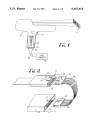
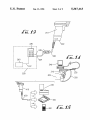
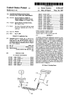
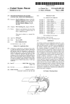
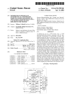
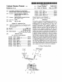
FIG. 1 is a diagrammatic view of a handheld laser
scanner attached to a host computer according to the
Heretofore there have been several systems for
achieving proper con?guration between the host com
puter and the peripheral. In a typical system, a particu
lar peripheral is con?gured to work with a particular
host computer, that is, the peripheral has contained a
single dedicated interface. Similarly, the host computer
present invention;
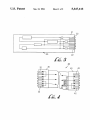
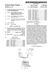
FIG. 2 is a diagrammatic view of an interface connec
tor system according to the present invention;
35
connector as in FIG. 2;
ent host computer, it was necessary to replace the inter
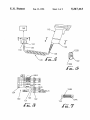
FIG. 5 is a diagrammatic view of an alternate periph
face software and hardware in the peripheral.
eral con?guration system;
The host computer may include a software selection
FIG. 6 is an end view of an end connector in FIG. 5
program in which the user inputs information identify
taken along line 6-—6;
ing the particular peripheral enabling the system to
FIG. 7 is an end view of an end connector in FIG. 5
have proper operation. Such an operation requires the
user to correctly input information into the host com
puter identifying the particular peripheral. Alternately,
taken along line 7—-7;
45
FIG. 5;
of the peripheral which informs the computer of the
host of the type of peripheral and software provides the
desired con?guration. Many of these systems still re
quire correct interface hardware.
FIG. 8 is a connector schematic illustrating an exam
ple cable connection scheme for the cable connector of
means are provided for scanning a code on the outside
type of peripheral. Some peripherals actually include
identifying signals which again inform the particular
FIG. 3 is a detailed diagrammatic view of a printed
circuit board of FIG. 2;
FIG. 4 is a detailed diagrammatic view of an edge
was con?gured to accept only a particular type of pe
ripheral. Any time the peripheral was moved to a differ
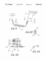
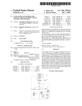
FIG. 9 is a diagrammatic view of an alternate periph
eral con?guration system;
50
'
FIG. 10 is an end view of an end connector in FIG.
9 taken along line 10—10;
FIG. 11 is an end view of an end connector in FIG.
9 taken along line 11-11;
In another con?guration technique, the peripheral
FIG. 12 is a connector schematic illustrating an exam
includes interface hardware for more than one host 55 ple cable connection scheme for the cable connector of
computer. When con?guring, the printed circuit board
of the peripheral requires certain hardware con?gura
FIG. 9;
tion in order to be correctly linked to a host computer.
bodiment;
FIG. 13 illustrates an alternate cable connection em
Such hardware con?guration may be effectuated by
FIG. 14 illustrates a cable scanning code operation;
manually actuable external switches or by internal 60 and
switches or “jumpers” within the printed circuit board
FIG. 15 illustrates various peripheral/host pairs.
(and/or within the host computer) which activate or
DESCRIPTION OF THE PREFERRED
deactivate certain components. Such an operation typi
EMBODIMENTS
cally requires the expertise of an electronics technician
or skilled user and is not a desirable ?eld operation to be 65
The preferred embodiments will now be described
performed by the typical user. It is desirable to have an
with reference to the drawings.
inexpensive and easy to use interconnection system
In FIG. 1, an example computer peripheral is illus
which can be effectively used by the average user.
trated as a handheld laser scanner 10 used for scanning