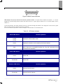
1
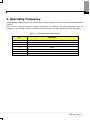
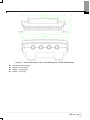
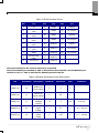
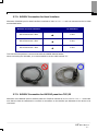
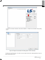
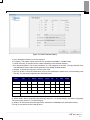
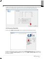
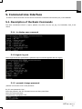
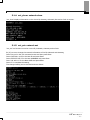
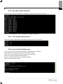
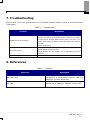
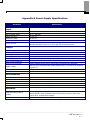
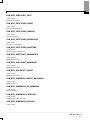
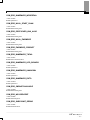
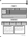
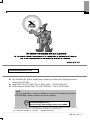
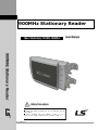
( 900MHz Stationary Reader Neo Stationary XCODE-IU9004 900MHz Stationary Reader Safety Precautions ● Read the safety precautions for an accurate use of the product. ● After reading the User Manual, place it in a location for other product users to easily read it. User Manual Thank you for purchasing the XCODE Reader of the LS Industrial Systems Co., Ltd. Safety Precautions The safety precautions are to prevent any accidents or dangers by using the product safely, so do comply with them. The safety precautions are classified into 2 types – “Caution” and “Warning” – and the respective details are as the following: Caution Warning Any cases in which severe injuries or death may occur if the instruction is not kept Any cases in which minor injuries or damages to the product may occur, if the instruction is not kept. The symbols in the product and the user manual have the following meanings. It is a symbol for you to be cautious of any dangers. It is a symbol for you to be cautious of any electric shock that may occur. After reading the user manual, place it in a location for other product users to easily read it. Before using the product, please fully read the user manual. Caution Do not deliver in an overload. It may cause physical or product damages. Input power in accordance to the conditions set in the product power rating standards. It may cause electric shock, fire, malfunctioning and damages or deterioration to the product. Only the experts are allowed to perform the maintenance work. It may cause physical damages and malfunctioning. Unplug the power cord and the Ethernet line when there is a severe lightning. It may cause lightning strike or fire. -2- Do not use the device near the hazardous location with potential of explosion. It may impact the high-frequency device. Do not disassemble or impact the product. It may cause electric leakage or fire. Do not use chemical substances or detergents to cleanse the reader. It may damage the product, so wipe off using a soft cloth. If the reader is severely heated during the use, unplug the power cord and contact us. It may cause fire. If the product is not used, turn off the power. It may shorten the device life and cause fire. Warning Make sure that the product is not exposed to rain or snow during the delivery. It may degrade the product performance. Do not store the product in a place that may wet or moist it. It may cause dielectric breakdown or degrade the product performance. Do not use it under high temperature or at highly wet areas. It may damage the product or degrade the product performance. Do not place the reader near magnetic objects including a credit card, a phone card, a bankbook or a ticket. The information may be damaged due to the reader magnetism. Dispose the product only at the designated location not to impact the environment. It may cause environmental pollution. Be careful not to impose too much pressure on the Antenna Port. When connecting the Antenna to the Reader, use appropriate torque for connection. Be careful not to drop the device. Although the product passed the standard drop performance test, it may influence the device life. Do not use or store it under extreme setting. It may impact the device performance. -3- Precautions for Use (1) Delivery & Installation Use an appropriate method to deliver the product in accordance to the weight. Do not pile up multiple devices without conforming to the set standards. Install in accordance to the rules set in the user manual. Do not open the cover when delivering the product. Do not place a heavy object on top of the product. Use ONLY the charger with a suitable power rating. Do not disassemble on your own, but consult with the expert. Use the product under the following conditions. Operating Temperature Humidity -10 ~ +50℃ -10% ~ 90% RH or under (No dew formation) Storage Temperature - 20 ~ 60℃ Environmental Setting No corrosive gas, combustible gas, oil residue or dust Altitude· Vibration Air Pressure Altitude of 1000m or under · 5.9m/sec²(=0.6g) or under 70 ~ 106 kPa (2) Control under Test Run (Operation) Check various program settings before operating the product. Do not input voltage that exceeds the voltage range specified in the user manual. (3) How to Use Do not remodel the interior of the product. Use the provided program and the user-convenient program. (4) Preventing the Malfunctioning If the reader is damaged and cannot be controlled, there are cases in which the device is left without caution. In such a circumstance, unplug the power and have it stored via A/S. -4- (5) Disposal Make sure that it is discarded as an industrial waste. (6) General The figures presented in the user manual for an accurate description may not correspond exactly to the actual product. -5- Overview XCODE-IU9004, a fixed type reader is able to communicate with the tag at the maximum speed of 400kbps. It is a reader designed to optimize the user application software and the reader itself. This user manual contains information on installing, connecting, setting, operating and upgrading the XCODE IU-9004 READER as well as the troubleshooting related matters, assuming that users acknowledge the network related information and the basic information on the EPC Global Gen2 and the RFID. -6- SRRC (State Radio Regulatory Commission) Approval This device is tested and designed in accordance to the regulations on the SRRC RFID equipments. Therefore, if the product is not used under the instructions specified in the user manual, there may be interference in the wireless communications due to the wireless power generated, used and emitted. If this is believed to impact the operation of the wireless devices including radios and televisions, switch on/off the power of the reader in order to identify whether there is any impact. The following methods can be applied to solve the interference generated: Changing the direction or the location of an antenna; Spacing between the device and the receiver (ex: Radio, Television); Consulting the matter with the expert on receivers. Caution: If the structure or the circuit of the device is altered, this may be violating the MIC rules, depriving the user rights. <Before You Begin> ! Warning Fully acknowledge the user manual before using the XCODE-IU9004 READER, and do not disassemble or remodel the reader without a permission to do so; otherwise it will invalidate the warranty. -7- Contents 1. OPERATING FREQUENCY ........................................................................................... 오류! 책갈피가 정의되어 있지 않습니다. 2. XCODE-IU9004 FUNCTIONS..........................................................................................................................................................- 11 2.1. RFID .......................................................................................................................................................................................................... - 11 2.2. HOST INTERFACE...................................................................................................................................................................................... - 11 2.3. RS232C PASSTHRU TCP/IP................................................................................................................................................................. - 11 2.4. GPIO.......................................................................................................................................................................................................... - 11 2.5. MANAGEMENT ........................................................................................................................................................................................... - 11 3. XCODE-IU9004 READER SETTING ............................................................................................................................................- 12 3.1. MINIMUM REQUIREMENTS OF THE SYSTEM & DEVICE ...................................................................................................................... - 12 3.2. READER I/O PORTS & STATUS .............................................................................................................................................................. - 13 3.3. READER INSTALLATION......................................................................................................................................................................... - 17 3.4. POWER CONNECTION ............................................................................................................오류! 책갈피가 정의되어 있지 않습니다. 3.5. ANTENNA CONNECTION.........................................................................................................오류! 책갈피가 정의되어 있지 않습니다. 3.5.1. Reader Output Setting ..................................................................................................................................................................- 17 3.6. ETHERNET CONNECTION(TCP/IP) ....................................................................................................................................................... - 18 3.7. SERIAL CONNECTION............................................................................................................................................................................... - 19 3.7.1. RS232C Connection for CLI........................................................................................................................................................- 19 3.7.2. RS232C Connection for Host Interface.......................................................................................................................................- 20 3.7.3. RS232C Connection for RS232C pass thru TCP/IP...................................................................................................................- 20 4. HOW TO USE THE READER.....................................................................................................................................................................- 21 4.1. DEMO GUI PROGRAM (NAME: XCODE) INSTALLATION ................................................................................................................. - 21 4.2. DESCRIPTION OF THE DEMO GUI PROGRAM (NAME: XCODE) .................................................................................................... - 21 4.3. TAG INVENTORY DEMO............................................................................................................................................................................ - 22 4.3.1. XCODE-IU9004 Setting ..............................................................................................................................................................- 22 4.3.2. Inventory Start/Exit.......................................................................................................................................................................- 25 5. COMMAND LINE INTERFACE .........................................................................................................................................................- 26 5.1. DESCRIPTION OF THE BASIC COMMANDS............................................................................................................................................ - 26 5.1.1. h : display user command ............................................................................................................................................................- 26 5.1.2. logout : log out..............................................................................................................................................................................- 26 5.1.3. passwd: change password............................................................................................................................................................- 26 5.1.4. net_show: network show ..............................................................................................................................................................- 27 5.1.5. net_set: network set ......................................................................................................................................................................- 27 5.1.6. sys_log: system log show..............................................................................................................................................................- 28 5.1.7. ver: system version show..............................................................................................................................................................- 28 5.1.8. host_if: host Interface set..............................................................................................................................................................- 28 5.1.9. bootloader: bootloader mode access command .........................................................................................................................- 29 5.1.10. fw_upgrade: firmware upgrade...................................................................................................................................................- 29 5.1.11. reboot ............................................................................................................................................................................................- 30 6. DESCRIPTION OF THE LSRCP (LSIS READER CONTROL PROTOCOL) PROTOCOL ................................- 31 6.1. OVERVIEW ...............................................................................................................................오류! 책갈피가 정의되어 있지 않습니다. 6.2. LSRCP CALL FLOW OF THE XCODE-IU9004 OPERATION ........................................................................................................... - 31 - -8- 7. TROUBLESHOOTING............................................................................................................................................................................- 33 8. REFERENCES..............................................................................................................................................................................................- 33 9. PURCHASE INFORMATION ....................................................................................... 오류! 책갈피가 정의되어 있지 않습니다. 10. QA SERVICE STANDARDS.............................................................................................................................................................- 44 10.1. INTRODUCTION TO THE QUALITY ASSURANCE SERVICE STANDARDS.......................................................................................... - 44 10.2. A/S TIPS................................................................................................................................................................................................. - 45 10.3. WARRANTY TERMS & CONDITIONS..................................................................................오류! 책갈피가 정의되어 있지 않습니다. -9- 1. Operating Frequency XCODE-IU9004 READER provides the instructions in using the product under the frequency bandwidth defined in Korea. SRRC requires using the frequency hopping method for the domestic UHF RFID bandwidth under the conditions of 4W or below. (Hopping in the intervals of 250 KHz for the 920.125 MHz~924.875 MHz range). Table 1-1 Operating Frequency by Channel No FREQ [MHz] 0 865.0 1 865.5 2 866.0 3 866.5 4 867.0 5 867.5 6 868.0 - 10 - 2. XCODE-IU9004 Functions 2.1. RFID The XCODE-IU9004 Reader supports ISO18000-6B/6C (EPC Global Gen2). It supports 4 mono-static antennas, and as an option, built-in antennas can be mounted. Contact our sales team on installing the built-in antennas before purchasing the device. 2.2. Host Interface The XCODE-IU9004 Reader is interfaced with the Host via Ethernet (TCP/IP, Port Number: 49380) or RS232C (115200 bps) and performs the Host Commands through the LSRCP (LS Industrial Systems‟ Reader Control Protocol) packet. 2.3. RS232C pass thru TCP/IP The XCODE-IU9004 Reader provides 2 RS232C (9600 bps) ports other than the RS232C port for Host Interface. The Host is able to transmit and receive the Raw Data with these two RS232C ports via TCP/IP. This function enables the Host to communicate with the external devices using the RS232C ports via TCP/IP in a remote place. The TCP/IP Port Number for each RS232C port is 49381 and 49382. 2.4. GPIO The XCODE-IU9004 Reader supports TTL Level-based 8 Output Channels and 4 Input Channels. 2.5. Management The XCODE-IU9004 Reader provides the Command Line Interface (hereinafter referred to as CLI) via telnet (TCP/IP) or RS232C (115200 bps) and also offers the Web Management. - 11 - 3. XCODE-IU9004 READER Setting The XCODE-IU9004 READER must be input with 24VDC power and refer to Appendix B for further details on the power supply unit. ! Caution It may damage the Reader, if a different type of power supply unit is used. 3.1. Minimum Requirements of the System & Device Windows 2000 (or higher), XP, or Linux O/S Installed Personal Computer: - RS-232 serial port - An Ethernet port The TCP/IP network equipment to connect the READER to a PC, MAC or any other Network terminals Ethernet port Standard Ethernet cable(s) UHF RFID antenna(s), relevant RF cables and RP-TNC male connector interface approved by LS Industrial Systems Standard, grounded DB9 serial cable - 12 - 3.2. Reader I/O Ports & Status Refer to Figure 3-1 for main part names of the XCODE-IU9004 READER. The XCODE-IU9004 READER supports the following ports. RJ-45 Ethernet port 4 Female RP-TNC RF antenna connectors Female DB-9 connector (RS232C for CLI, GND No5, TXD No2 and RXD No3) Female DB-25 connector It includes one RS232C port for Host Interface, two RS232C ports for pass thru TCP/IP, four TTL-level inputs and eight TTL-level outputs. Refer to Table 3-2 for further details on the electrical characteristics of the GPIO. Refer to Figure 3-3 for the Pin location. ` Figure 3-1 XCODE-IU9004 Reader Port Connections of the LS Industrial Systems - 13 - Figure 3-2 External Dimensions of the LS Industrial Systems XCODE-IU9004 Reader Horizontal: 190.00 [mm] Vertical: 137.00 [mm] Height: 70.50 [mm] Weight: 2.50 [kg] - 14 - Table 3-1 DB-25 Connector Pin-Out Pin I/O Pin I/O Pin I/O 1 5V 10 GPIN3 19 GPOUT5 11 GPIN2 20 No connect 12 GPIN1 21 GPOUT6 13 GPIN0 22 No connect 14 GPOUT0 23 GPOUT7 15 GPOUT1 24 No connect 25 No connect RS232C RXD (Ch0) RS232C TXD (Ch0) RS232C RXD (Ch1) RS232C TXD (Ch1) RS232C RXD (Ch2) 2 3 4 5 6 7 GND 16 GPOUT2 8 RS-232 TXD (Ch2) 17 GPOUT3 9 No connect 18 GPOUT4 Note) Pins labeled as ‘No connect’ shall not be connected. Note) The RS232C port marked as ‘Ch0’ is allocated for Host Interface and the RS232C port marked as ‘Ch1’ or ‘Ch2’ is allocated for RS232C pass thru TCP/IP. Table 3-2 Electrical Specifications of the GPIO Interface Pin Parameter Description Minimum Maximum Unit GPIN[3:0] VIH HIGH-level input voltage 2 5 V GPIN[3:0] VIL LOW-level input voltage 0 0.8 V GPIN[3:0] ILI Input Leakage Current -5 5 μA Vin=0–5V GPOUT[7:0] VOH HIGH-level output voltage 3 3.3 V Iout = 100 μA VOL LOW-level output voltage 0 0.25 V Iout = -100 μA GPOUT[7:0] Conditions - 15 - Figure 3-3 DB-25 Female Connector LED displays the power, status and antenna operation status. The parts where marked as Antenna 1, 2, 3 and 4 display the corresponding antenna status and when turned on, a green light is switched on. For further details, refer to Table 3-3. In the initial booting, the reader antenna function is checked through the Reader’s self-diagnosis function and a green light is turned on the LED after the function is checked. It is not an abnormal operation. Instead it displays a normal status of the antenna port. Table 3-3 LED Status Indicators Status LED Action Red/Green Light Switching On/Off (1 Hz) Green Reader Operation Displays the Boot loader mode Displays the Reader mode (Displays the Normal status) Red Displays the Reader mode (Displays the Error status) Error code can be identified through the “sys_log” command of the Command Line Interface. Power LED Action Reader Operation Green Power ON Turned ON Power OFF Antenna LED Action Green Turned ON Reader Operation Antenna Port RF Active Antenna Port RF Inactive - 16 - 3.3. READER Installation When installing the Reader, avoid direct sunlight, humid places, extremely high/low temperatures, severe vibrations, magnetic impacts or several combinations of the mentioned environmental settings. These settings may degrade the reader‟s performance or shorten the device life. 3.4. Power Connection When the reader is connected to the power (100-240VAC, 50-60Hz), a green light is turned on the LED. It takes about 5 seconds for the reader to boot after the light is turned on. No commands are able to control the reader before the booting ends. After the booting is completed, a green light is turned on the Status LED. 3.5. Antenna Connection The XCODE-IU9004 READER supports 4 two-way, full duplex TX/RX ports (Mono - Static). Caution) The antennas unused must be disconnected for storage. 3.5.1. Reader Output Setting The XCODE-IU9004 READER is able to set the output within the range specified below in accordance to the KCC standards. When delivered from the factory, it is set as 30dBm in consideration of the antenna gain of 6dBi. Up to 32dBm can be output. Below is a list of antennas compatible with the antennas provided by LS Industrial Systems. Cushcraft Model Number S9028PCL/R (left- or right-hand CP); 6 dBi gain, with integrated pigtail to RP-TNC female connector Sensormatic Electronics Corp. model number IDANT20TNA25 with 25 foot Belden 7806A RG-58 coaxial cable (0.1 dB per foot loss); 5.5 dBi composite gain Sensormatic Electronics Corp. model number IDANT10CNA25 with 25 foot Belden 7806A coaxial cable (0.1 dB per foot loss); 3.5 dBi composite gain Sensormatic Electronics Corp. model number IDANT10CNA25 with 6 foot Belden 7806A coaxial cable (0.1 dB per foot loss); 5.4 dBi composite gain Caution) If incompatible antennas are used, they may degrade the reader performance. - 17 - 3.6. Ethernet Connection (TCP/IP) Ethernet port is used to connect the Reader to the network. If the network is able to communicate with the Reader via a default IP configuration (192.168.1.100/ 255.255.255.0), check the connection as described below. Make sure that the Host Computer is in the same Subnet as the Reader. Reader Computer Ethernet HUB Ethernet Figure 3-4 Ethernet Connection Apply either method to connect the Ethernet port of the Computer to the XCODE-IU9004 READER. Use the Ethernet Router or the Switch in the Reader subnet for connection. Use the Ethernet Cross Cable to directly connect to the PC and use the IP address designated as the fixed value to the Reader subnet. Use the “ping” command at the Host through the command input interface of the PC on the reader‟s IP to check the TCP/IP connection. - 18 - 3.7. Serial Connection 3.7.1. RS232C Connection for CLI The DB-9 pins and the PC COM ports are connected to the RS232C Direct Cable as described below to connect the XCODE-IU9004 READER CLI via RS232C. RS232C for CLI PC COM Port DB-9 Connector 2 Pins → 2 Pins DB-9 Connector 3 Pins → 3 Pins DB-9 Connector 5 Pins → 5 Pins The Hyper Terminal provided from Microsoft Windows or a similar program (Tara Term for Window or Minicom for Linux) is used for CLI connection. Communication parameters of the Hyper Terminal must be set as shown in Figure 3-5. Figure 3-5 Serial Port Configuration When a screen is displayed, insert the password. In default, it is set as below. Password: xcode - 19 - 3.7.2. RS232C Connection for Host Interface Allocation of RS232C pins for Host Interface is marked as „Ch0‟ in Table 3-1 and it is connected to the PC COM as described below. RS232C for Host Interface PC COM Port DB-25 Connector 2 Pins → 3 Pins DB-25 Connector 3 Pins → 2 Pins DB-25 Connector 7 Pins → 5 Pins The Host uses the packet to communicate with the XCODE-IU9004 Reader. When connecting the 232Cable, it is recommended to use the cable marked “O”. 3.7.3. RS232C Connection for RS232C pass thru TCP/IP Allocation of the RS232C pins for RS232C pass thru TCP/IP is marked as „Ch1‟ or „Ch2‟ in Table 3-1 and make sure that the data is transmitted or received in accordance to the RS232C pin allocated to the device to be connected. - 20 - 4. How to Use the READER 4.1. Demo GUI Program (Name: XCODE) Installation Execute „setup.exe‟ in the CD for installation. After the installation is completed, a shortcut icon as shown below is created on screen. 4.2. Description of the Demo GUI Program (Name: XCODE) Configure Settings Button: Select and set a Host Interface Type (TCP/IP or RS232cC) to be connected to the XCODE-IU9004 reader. Exit Button: It ends the program. Start Inventory Run Button: It starts the Tag Inventory function. Clear Inventory Button: It deletes the tag displayed on screen. - 21 - 4.3. Tag Inventory Demo This is a Tag Inventory Demo that is applied with the Demo GUI Program (Name: XCODE). Double click on the XCODE icon displayed on screen to execute it. Figure 4-1 is the main screen of the Demo GUI Program (Name: XCODE; hereinafter referred to as „Program‟). Figure 4-1 Reader Controller Program 4.3.1. XCODE-IU9004 Setting 1) Connection: Click on the „Configure Settings’ button as shown below to display a “Reader Setting” dialog box. - 22 - 2) Select the Connection Interface: Select either „RS232C‟ or „TCP/IP‟ from the Reader setting dialog screen. Figure 4-2 Program Communication Port Setting (When ‘TCP/IP’ is selected) 3) Select the Gen2 Parameter: It is able to set the Antenna and Gen2 related parameters from the Reader setting dialog screen. - 23 - Figure 4-3 Gen2 Parameter Setting a) Ant: It displays whether to use the antenna. b) Tx(dBm): The reader output power can be set within the 22dBm ~ 32dBm range. c) Dwell Time(ms): It sets the time of reader operating in the selected antenna. d) Rx Sensitivity(dBm): The receive sensitivity of a Tag response is set here. The tag response time that falls below the set value will be ignored by the XCODE-IU9004 Reader. e) Region: It selects the frequency country to be used. f) Air Link Profile: It sets the parameters such as the transmission speed when communicating with the Tag. The set values supported are described below. Link Profile Mod X PW(us) Rtcal(us) Trcal(us) DR M TRExt LF(KHz) DSB 1.00 12.50 75.00 200.00 8.00 0 1 40 1 PR 0.50 12.50 62.50 85.33 21.33 4 1 250 2 PR 0.50 12.50 62.50 71.11 21.33 4 1 300 3 DSB 0.50 3.13 15.63 20.00 8.00 0 1 400 Index Type 0 4 Exclusive for IS0 18000-6B g) Search Mode: When recognizing the fixed tag, select „A<->A (Single Target)‟ and when recognizing the moving tag, select „A<->B (Dual Target). h) Session: It is a field to select the tag session mentioned in ISO18000-6C (EPC Global Gen2). i) Init Q: It is a field to set the initial Q value. - 24 - 4) Apply the Set Value: Click on the „Apply‟ button to set the XCODE-IU9004 Reader with the selected values. Up to 2 XCODE-IU9004 readers can be executed with the Reader Setting dialog box. 4.3.2.Inventory Start/Exit 1) Click on the „START Inventory Run’ button to implement the Tag Inventory function. 2) When the Tag Inventory function is started with the START Inventory Run button, this button is changed to the START Inventory Stop button. Click on the START Inventory Stop button to stop the Inventory function. - 25 - 5. Command Line Interface A Serial or Telnet connection can be used to access the Command Line Interface (CLI) of the READER. 5.1. Description of the Basic Commands The basic commands include h, logout, passwd, net_show, net_set, sys_log, ver, bootloader, host_if and reboot. 5.1.1. h: display user command 5.1.2.logout: log out Insert „logout‟ and then press Enter. A password input command appears after the logout. 5.1.3. passwd: change password „passwd‟ is a function to set a new password. Ex) If a new password is „lsis'; Insert the passwd in the CLI command screen and then press Enter. Insert „lsis‟ and press Enter. The password is changed to ‘lsis‟. - 26 - 5.1.4. net_show: network show „net_show‟ displays information on the device IP, Gateway, Submask, Mac and so forth on screen. 5.1.5. net_set: network set „net_set‟ is a function to set the current IP, Submask, Gateway and so forth. Ex) If you are to change the network information of the IP, Submask and Gateway; Insert „net_set‟ in the CLI command screen and then press Enter. Insert „192.168.1.102‟ for the New IP and press Enter. Insert „255.255.255.0‟ for the New SUBMASK and press Enter. Inert „192.168.1.1‟ for the New GWIP and press Enter. Insert „Y‟ to complete the setting. The changed setting can be checked as shown below. - 27 - 5.1.6. sys_log: system log show Insert „sys_log‟ and then press Enter. It will display a system log message of the device. The Error Code displayed in the log message is described in Appendix C. 5.1.7. ver: system version show Insert „ver‟ and then press Enter. It will display a system version of the device. 5.1.8. host_if: host Interface set „host_if‟ is a function to set the host interface as either Ethernet or RS232C. Ex) If „RS232C‟ is selected for the host communication mode; Insert „host_if‟ in the CLI command screen and then press Enter. Insert „0‟ to select the Ethernet communication. Insert ‘y’ and then press Enter to complete the setting. Refer to the screen shown below. - 28 - 5.1.9. bootloader: bootloader mode access command Insert „bootloader‟ and then press Enter. After 5 seconds, it is operated under the bootloader mode. In the bootloader mode, the Status LED flickers in red and yellow for every second. Under the bootloader mode, the commands such as h, logout, passwd, net_show, net_set, fw_upgrade, reboot and so forth can be executed. These commands - h, logout, passwd, net_show, net_set and reboot – are the same as the basic commands. To exit the bootloader mode, rebooting should be executed with the reboot command. 5.1.10. fw_upgrade: firmware upgrade „fw_upgrade‟ command is used to upgrade the firmware through the TFTP server. The distributed firmware is a binary file called „app.bin‟. Ex) If the TFTP server is 192.168.1.152, follow the procedure described hereinafter. Insert „fw_upgrade‟ in the CLI command screen and then press Enter. Insert „192.168.1.152‟ for IP and then press Enter. Insert „Y‟. Upgrade is under progress as shown below. - 29 - Refer to “How to upgrade XIU9004‟s firmware with Tftp32”, if a demo freeware, Tftp32 is recommended for the TFTP server. 5.1.11. reboot Insert „reboot‟ and then press Enter. The device will be rebooted. - 30 - 6. Description of the LSRCP (LSIS Reader Control Protocol) 6.1. Overview LSRCP is a LS Industrial Systems Protocol with more functions that is developed based on the Mobile RFID Reader Control Protocol (MRFS-1-06). The XCODE-IU9004 Reader supports the LSRCP via TCP/IP or RS232C. Further details on the LSRCP supported by the XCODE-IU9004 Reader are contained in the “LSRCP for XIU9004” document. A separate SDK is offered to use the LSRCP under the C# and Java settings. 6.2. LSRCP Call flow for the XCODE-IU9004 Operation The LSRCP Call flow for a general Tag Inventory of the XCODE-IU9004 Reader is as shown below. Tag Writing, Reading, Kill, Lock and so forth also conform to this Call flow. - 31 - - 32 - 7. Troubleshooting Refer to Table 7-1 to solve general issues. For an additional technical support, contact LS Industrial Systems (1588-2080). Table 7-1 Troubleshooting Troubles Resolutions In most cases, the READER OS is still booting or the TCP/IP is disconnected. Retry it or “ping” the Reader to check the connection. READER TCP/IP access denied. If more than 50 seconds elapse after the power is turned on, turn off the power and try to reconnect. Retry the Reader “ping” after 50 seconds. Check the IP setting. Identify the error causes through the „sys_log‟ command. Tag cannot be read. Check whether the Tag is correct. Check whether the Link profile is set in accordance to the Air protocol. Power LED cannot be turned ON. Check the power and the adaptor connection status. 8. References Table 8-1 Reference MIB-2 RFC 1213 RFC 3986 Reference Description Management Information Base for Network Management of TCP/IP-based internets: MIB-II. K. McCloghrie, M. Rose. March 1991. Uniform Resource Identifier (URI): Generic Syntax. T. Berners-Lee, R. Fielding, L. Masinter. January 2005. - 33 - Appendix A LSIS Factory Default Configuration Password: xcode IP: 192.168.1.100 Gateway IP: 192.168.1.1 Subnet mask: 255.255.255.0 Host Interface: Ethernet (TCP/IP, Port Number: 49380) - 34 - Appendix B Power Supply Specifications Parameter Specification Input Rated input voltage Input voltage range Rated frequency Frequency range Rated input current 100 V ~ 240 V ac 90 V ~ 264 V ac 50~60 Hz 47~63 Hz 1.5 A at 115 / 0.75 A at 230 V ac (full load) Inrush current Under the Full load, nominal ac input voltage, 25°C, cold start (Neither damages will occur nor the input fuse be disconnected.) Output Output voltage Output min. current Line regulation Load regulation Over voltage protection Over current protection Short circuit protection Ripple voltage Efficiency Leakage current 24 V dc at 2.5 A 0A ± 2% ± 5% ≤ 31 V dc max.(Zener clamp ) ≤ 5 A (Auto recovery function) Electric leakage during the DC output will not generate any damages. 240 mV (p-p) (at 20 MHz and output parallel with 0.1 µF and 10 µF capacitor to ground.) 80% min. (at nominal input voltage and full load) 0.25 mA Environmental Cooling Storage temperature Operating temperature Storage humidity Operating humidity by natural convection -20°C ~ +60° C -10°C ~ +50° C 5~95% RH (non-condensing) 20~85% RH (non-condensing) Reliability Mean time before failure (MTBF) Power supply unit is designed to have 50,000 hours of mean time between failures (MTBF) when operated under the following conditions: 80% max. load at 25°C, nominal input voltage. Burn-in test 4 hours at 40°C max., nominal input voltage, 80% of max. load - 35 - Appendix C Error Code CSM_ERR_MBPRDADDR • Value: 0x0005 R2000 Register Connection Error CSM_ERR_MBPWRADDR • Value: 0x0006 R2000 Register Connection Error CSM_ERR_SUBSYSINIT_CPU • Value: 0x0007 R2000 Initialization Error CSM_ERR_SUBSYSINIT_DBG • Value: 0x0008 R2000 Initialization Error CSM_ERR_SUBSYSINIT_CSM • Value: 0x0009 R2000 Initialization Error CSM_ERR_SUBSYSINIT_OEMCFG • Value: 0x000A R2000 Initialization Error CSM_ERR_SUBSYSINIT_HOSTIF • Value: 0x000B R2000 Initialization Error CSM_ERR_SUBSYSINIT_TILIF • Value: 0x000C R2000 Initialization Error CSM_ERR_SUBSYSINIT_BIST • Value: 0x000D R2000 Initialization Error CSM_ERR_SUBSYSINIT_GPIO • Value: 0x000F R2000 Initialization Error CSM_ERR_SUBSYSINIT_RFTC • Value: 0x0010 R2000 Initialization Error - 36 - CSM_ERR_SUBSYSINIT_PROT • Value: 0x0011 R2000 Initialization Error CSM_ERR_PROTSCHED_UNKST • Value: 0x0012 R2000 Malfunctioning Error CSM_ERR_PROTSCHED_AMBANT • Value: 0x0013 Antenna Setting Error CSM_ERR_PROTSCHED_BADREGION • Value: 0x0017 Operating Area Setting Error CSM_ERR_PROTSCHED_BADFTIME • Value: 0x0018 Frequency Hopping Setting Error CSM_ERR_SUBSYSINIT_OEMHWOPTS • Value: 0x001A R2000 Initialization Error CSM_ERR_SUBSYSINIT_NVMEMUPD • Value: 0x001B R2000 Initialization Error CSM_ERR_DEV_RESET_FAILED • Value: 0x001D R2000 Initialization Error CSM_ERR_NVMEMUPD_ABORT_MACERRNO • Value: 0x001E R2000 Update Error CSM_ERR_NVMEMUPD_INT_MEMBNDS • Value: 0x001F R2000 Update Error CSM_ERR_NVMEMUPD_ENTRYKEY • Value: 0x0020 R2000 Firmware Check Sum Error CSM_ERR_NVMEMUPD_NVFLUSH • Value: 0x0021 - 37 - CSM_ERR_NVMEMUPD_WRVERFAIL • Value: 0x0022 R2000 Update Error CSM_ERR_INVAL_START_CHAN • Value: 0x0023 R2000 Malfunctioning Error CSM_ERR_PROTSCHED_UNK_ALGO • Value: 0x0024 R2000 Malfunctioning Error CSM_ERR_INVAL_PWRMODE • Value: 0x0025 R2000 Malfunctioning Error CSM_ERR_PWRMODE_CORRUPT • Value: 0x0026 R2000 Malfunctioning Error CSM_ERR_NVMEMUPD_TXFAIL • Value: 0x0027 R2000-Host Transmission Error CSM_ERR_NVMEMUPD_UPD_BOUNDS • Value: 0x0028 R2000 Update Error CSM_ERR_NVMEMUPD_UNKNOWN • Value: 0x0029 R2000 Update Error CSM_ERR_NVMEMUPD_RXTO • Value: 0x002A R2000 Update Error CSM_ERR_CMDNOTAVAILABLE • Value: 0x002D R2000 Malfunctioning Error CSM_ERR_NOCORDICDEF • Value: 0x002E R2000 LBT Setting Error CSM_ERR_SUBSYSINIT_DEBUG • Value: 0x002F R2000 Initialization Error - 38 - CSM_ERR_SUBSYSINIT_TRACE • Value: 0x0030 R2000 Initialization Error HOSTIF_ERR_RXUNKNOWN • Value: 0x0107 R2000 Malfunctioning Error HOSTIF_ERR_TXUNKNOWN • Value: 0x0108 R2000 Malfunctioning Error HOSTIF_ERR_BADIFSTATE • Value: 0x0109 R2000 Communication Error HOSTIF_ERR_STRDESCINIT • Value: 0x010D R2000 Initialization Error HOSTIF_ERR_INVALIDSETFREQARG • Value: 0x011E R2000 Frequency Setting Error RFTC_ERR_BADFRQCHAN • Value: 0x0300 R2000 PLL Setting Error RFTC_ERR_BADHOPMODE • Value: 0x0301 R2000 Hopping Frequency Setting Error RFTC_ERR_PLLFAILEDTOLOCK • Value: 0x0302 R2000 PLL Lock Error RFTC_ERR_XCVRADC_TIMEDOUT • Value: 0x0303 R2000 Malfunctioning RFTC_ERR_FILTTUNE_TIMEOUT • Value: 0x0304 R2000 Malfunctioning RFTC_ERR_AMBIENTTEMPTOOHOT • Value: 0x0305 R2000 Ambient Temperature Error - 39 - RFTC_ERR_XCVRTEMPTOOHOT • Value: 0x0306 R2000 Surface Temperature Error RFTC_ERR_PATEMPTOOHOT • Value: 0x0307 PA Temperature Error RFTC_ERR_PADELTATEMPTOOBIG • Value: 0x0308 PA Temperature Error RFTC_ERR_REVPWRLEVTOOHIGH • Value: 0x0309 Antenna Disconnection Error RFTC_ERR_BADIFLNAGAIN • Value: 0x030A R2000 IF PA Gain Setting Error RFTC_ERR_TXRF_BIT_FAILED • Value: 0x030B R2000 RF Transmitting Malfunction Error RFTC_ERR_TXRF_BYTE_FAILED • Value: 0x030C R2000 RF Transmitting Malfunction Error RFTC_ERR_TXRF_EOT_FAILED • Value: 0x030D R2000 RF Transmitting Malfunction Error RFTC_ERR_TXRF_PREAM_FAILED • Value: 0x030E R2000 RF Transmitting Malfunction Error RFTC_ERR_TXRF_FSYNC_FAILED • Value: 0x030F R2000 RF Transmitting Malfunction Error RFTC_ERR_RXRF_ISR_TIMEOUT • Value: 0x0310 R2000 RF Receiving Malfunction Error RFTC_ERR_INVALIDLINKPARMS • Value: 0x0311 R2000 Link Profile Parameter Setting Error - 40 - RFTC_ERR_RXRF_INTERPKTTIMEOUT • Value: 0x0312 R2000 RF Receiving Malfunction Error RFTC_ERR_NO_LINKPROFHDR • Value: 0x0313 R2000 Link Profile Parameter Setting Error RFTC_ERR_PROFILE_INVALID • Value: 0x0314 R2000 Link Profile Data Error RFTC_ERR_DBMVALOUTOFRANGE • Value: 0x0315 R2000 Malfunctioning Error RFTC_ERR_FWDPWRLEVTOOHIGH • Value: 0x0316 R2000 PA Output Error RFTC_ERR_NO_GROSSPWRENTRY • Value: 0x0317 R2000 Internal Data Error RFTC_ERR_TARGETPWRTOOHIGH • Value: 0x0318 R2000 PA Output Setting Error RFTC_ERR_ANTENNADISCONNECTED • Value: 0x031A R2000 Antenna Disconnection Error RFTC_ERR_UNREC_HWOPTFORMAT • Value: 0x031B R2000 Internal Data Error RFTC_ERR_HWOPT_BADFWDPWROPT • Value: 0x031C R2000 Internal Data Error RFTC_ERR_HWOPT_BADREVPWROPT • Value: 0x031D R2000 Internal Data Error RFTC_ERR_HWOPT_BADDRMFILTOPT • Value: 0x031E R2000 Internal Data Error - 41 - RFTC_ERR_HWOPT_BADAMBTEMPOPT • Value: 0x031F R2000 Internal Data Error RFTC_ERR_HWOPT_BADPATEMPOPT • Value: 0x0320 R2000 Internal Data Error RFTC_ERR_HWOPT_BADXCVRTEMPOPT • Value: 0x0321 R2000 Internal Data Error RFTC_ERR_HWOPT_BADANTSENSOPT • Value: 0x0322 R2000 Internal Data Error RFTC_ERR_BADIFLNAAGCRANGE • Value: 0x0323 R2000 Malfunctioning Error RFTC_ERR_BAD_RFLNA_GAIN_REQ • Value: 0x0327 R2000 Internal Gain Setting Error RFTC_ERR_BAD_IFLNA_GAIN_REQ • Value: 0x0328 R2000 Internal Gain Setting Error RFTC_ERR_BAD_AGCMIX_GAIN_REQ • Value: 0x0329 R2000 Internal Gain Setting Error RFTC_ERR_HWOPT_BADFWDPWRCOMPOPT • Value: 0x032A R2000 Internal Setting Error RFTC_ERR_INVALID_PLL_DIVIDER_VALUE • Value: 0x032B R2000 PLL Setting Error RFTC_ERR_SJC_EXTERNALLOTOOLOW • Value: 0x032C R2000 SJC Malfunctioning Error RFTC_ERR_SJC_EXTERNALLONOTSELECTED • Value: 0x032D R2000 SJC Malfunctioning Error - 42 - RFTC_ERR_BADLOSOURCE • Value: 0x032E R2000 Internal Setting Error RFTC_ERR_INVALID_OEM_PROFILE_HEADER • Value: 0x0331 R2000 Internal Data Error RFTC_ERR_FWDPWRLEVERROR • Value: 0x0336 R2000 PA Level Output Error RFTC_ERR_HWOPT_BADPABIASDACCTL • Value: 0x0337 R2000 Internal Data Error RFTC_ERR_GROSSGAIN_CONFIG_INVALID • Value: 0x033A R2000 Internal Data Error TILDENIF_ERR_RDFAILSAFE • Value: 0x0602 R2000 Internal Register Error TILDENIF_ERR_INVALPWRST • Value: 0x0603 BIST_ERR_RF_IO_REG_CHK • Value: 0x0701 R2000 Malfunctioning Error BIST_ERR_RF_REG_BITS • Value: 0x0702 R2000 Malfunctioning Error - 43 - 9. Purchase Information Model Name: Date of Purchase: Serial No: Memo: _____________________________________________________________________________ _____________________________________________________________________________ _____________________________________________________________________________ _____________________________________________________________________________ _____________________________________________________________________________ _____________________________________________________________________________ _____________________________________________________________________________ _____________________________________________________________________________ _____________________________________________________________________________ _____________________________________________________________________________ _____________________________________________________________________________ _____________________________________________________________________________ 10. Quality Assurance Service Standards 10.1. Introduction to the Quality Assurance Service Standards QA Related Claims Repair Possible Performance/Function Troubles under a normal operation Repair Impossible In case of a Defect Recurring troubles for the same defect repaired (4th time) Although there are repair parts, it is not possible to perform the repair. When the critical part must be repaired right after the purchase Performance/Function Troubles due to the Customer‟s intentional negligence Repair Possible An abnormal appearance cannot be Repair repaired; only the Impossible performance troubles can be fixed QA Related Claims Within the After the Warranty Warranty Period Period Free Repair Free Repair Exchange the product Charged Repair Exchange the product - Exchange the product - Charged Repair Exchange the product after collecting the amount equivalent to the charged repair - - 44 - 10.2. A/S Tips ■ If any abnormalities occur as using the product, reread the user manual and then contact our customer service team by (041)550-8437 or 1544-2080. We will promptly take appropriate actions. 10.3. Warranty Terms and Conditions ■ Free A/S Service We will repair the product free-of-charge, if the product is malfunctioning under a normal status from the date of purchase to the warranty termination. ■ Charged A/S Service Under the following situations, we will repair the product by charging a suitable service fee (repair cost, parts cost and etc): 1. The warranty period has terminated; 2. If within the warranty period; ● Troubles owing to the natural disasters (fire, salt damage, gas damage, earthquake, damage from storm and flood, lightning strike, abnormal power input and etc); ● Troubles due to the careless handling and use (drop, impact and damage) ● Troubles because a person other than the service center engineer repaired the product; ● If the product is disassembled or the name plate is not attached; ● Troubles due to the abnormal power input; ● If it is used for other purposes; ● If an user remodeled the interior part; ● Unexpected problems occurred which were impossible to be anticipated at the time the product was manufactured; ■ We are not responsible for any safety accidents that occur due to the customer‟s negligence. - 45 - Warranty Product Name LS Industrial Systems XCODE Date of Purchase Model Name XCODE-IU9004 Warranty Period Name Address Phone No. Name Address Phone No. Customer Sales Store This product is manufactured under a strict quality control and inspection processes by the LS Industrial Systems Technical Team. The warranty period is generally 12 months from the date of purchase. If the date of purchase is not filled in, 12 months from the date of manufacture will be applied. However, this can be changed in accordance to the contract terms and conditions. User Manual Version No. Issued Date Revision Version No. 1 2010.05 First Version 1.00 Remarks Environment Management How to Dispose the Product LS Industrial Systems prioritizes the LS environmental in designed to protect the environment. all When discarding the product, the managing the preservation company, and executives and staff members do their Industrial Systems Reader is aluminum parts can be recycled. best to achieve a more pleasant environment for all to share. - 46 - We cherish the relations with our customers! We, LS Industrial Systems, are an enterprise for customers and of customers prioritizing the quality and the customer service and endeavoring to satisfy all customers. We, LS Industrial Systems, prioritize the product quality and customer service. 소비자를 위한 소비자에 의한 기업임을 굳게 다짐하며 고객 여러분의 만족을 위해 최선을 다하겠습니다. LS Industrial Systems Co. Ltd. HQ: LS Tower(4F) 1026-6, Hogye-dong, Dongan-gu, Anyang City, Gyeonggi Province, Postal Code: 431-848 Sales Team: TEL.(02) 2034-4071~5, 4080, 4090 FAX.(02) 2034-4077 RFID Customer Service Team: TEL.(041) 550-8439 FAX.(041) 550-8425 A/S For any troubles or inquires related to using the LS Industrial Systems RFID READER, please contact our service center. Technical Support & A/S Service Center Call (Country-wide): 1544-2080 ※ The product contained in the user manual may not be manufactured, or be changed, so please check before the purchase. ※ Contact LS Industrial Systems for any abnormalities or inconveniences in using the product. ⓒ LS Industrial systems Co., Ltd 2007 All Rights Reserved. - 47 -