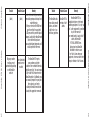
1
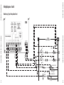
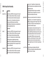
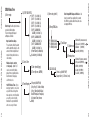
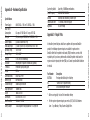
USER’S GUIDE
USER’S GUIDE
XR50 User’s Guide
494 S. Emerson Ave., Suite E, Greenwood, IN 46143
Telephone 317-885-6330 • [email protected]
www.omnisite.com
v. 2.0
USER’S GUIDE
494 S. Emerson Ave., Suite E, Greenwood, IN 46143
Telephone 317-885-6330 • [email protected]
www.omnisite.com
v. 2.0
USER’S GUIDE
XR50 User’s Guide
©2009 OmniSite
OmniSite XR-50 User’s Guide
INSPECT CONTENTS IMMEDIATELY
AND FILE CLAIM WITH DELIVERING
CARRIER FOR ANY DAMAGE
Seller shall not be liable for any injury, loss or damage direct or consequential
arising out of the use or the ability to use the product. This warranty gives specific legal
rights. You may have other rights that vary from state to state. Some states do not
allow the exclusion or limitation or incidental or consequential damages, so that the
above limitation of exclusion may not apply to you
YOU ARE RESPONSIBLE FOR DAMAGE TO YOUR
UNIT IF RETURNED IMPROPERLY PACKED.
NOTICE
SAVE THE BOX
AND
PACKING MATERIAL
OmniSite XR-50 User’s Guide
If it appears within one (1) year from the date of delivery to Purchaser that any products
or component parts do not conform exactly to the specifications and physical dimensions referred to above, and the Purchaser, at its expense, returns the product or component parts to the Seller together with a report of defects, the Seller shall review the
inspection report and inspect the items and shall authorize, at its option, either the
repair or replacement of any non-conforming products or component parts, whether on
warranty, contract of negligence, shall not in any case exceed the amount to be paid by
the Seller in obtaining and repair or
replacement of non-conforming products or component parts, and upon expiration of the
warranty period, all liability of the Seller shall be terminated. This warranty does not cover
damage due to acts of God (fire, flood, lightning, etc.) nor product misuse and accidental damage.
©2009 OmniSite
Limited Warranty
4
3
WARNING: The individual user should take care to determine prior to use whether
this device is suitable, adequate or safe for the use intended. Since individual applications are subject to great variation, the manufacturer makes no representation or
warranty as to suitability or fitness of these devices for any specific application.
©2009 OmniSite
OmniSite XR-50 User’s Guide
Danger: means if the safety information is not followed, someone will be
seriously injured or killed.
WARNING: To reduce risk of fire, electric shock, or injuries
always disconnect all sources of electrical power
before servicing or cleaning.
Warning: means if the safety information is not followed, someone could be seriously injured or killed.
Introduction
Caution: means if the safety information is not followed, someone may be
seriously injured or killed.
Congratulations - you just bought the best. The OmniSite system provides two-way
communications using our patented WINGS™ (Wireless Information Network Gateway
Standard) over a cellular network. The low cost of the OmniSite method makes
remote monitoring very affordable, and allows our devices to operate on GSM
networks worldwide. We have the most complete coverage and best reputation in the
industry.
1. To reduce the risk of fire or shock hazard, connect OmniSite RTU
directly to a 120 VAC electrical circuit. Do not use extension cords
for permanent installation.
2. Cover of OmniSite RTU must be securely closed to prevent water
damage and electrical shock.
3. Never operate your OmniSite RTU while any part is missing or
damaged in any manner.
OmniSite wireless monitoring devices provide a low cost wireless system for remote
monitoring, measurement, and data collection anywhere wherever there is GSM
service, Worldwide.
4. To reduce the risk of electrical hazard or damage, do not tilt, jolt or
tip RTU while unit is powered-on.
Overview
5. To reduce the risk of accidental electrical shock, do not touch the
electrical terminals or controls with wet hands.
6. Note the warning label shown below.
The OmniSite XR50 is a 10-channel monitoring device that has been optimized
for use by the water and wastewater utilities. It is designed for indoor or
outdoor environments, and operates from 120VAC or +15-20 VDC solar panels and
OmniSite XR-50 User’s Guide
6
5
Safety Signal Words
©2009 OmniSite
General Safety Instructions
Installation and Operation is Very Simple:
Please note that your OmniSite product is a cellular device. No matter how
good the installation looks, without cellular reception, your device will not work!
Therefore, your first step is to determine that suitable cellular service is available at
the installation location BEFORE you start your actual installation. Connect your
OmniSite unit to a temporary extension cord, and plug it in at the installation location.
Look at the cellular signal strength LED on the XR50. If it is GREEN, you have a good
signal, and can proceed with installation. If NOT GREEN, call OmniSite at 317-8856330 to determine that your cellular signal strength is suitable. Once this is verified
you can move-on to installing your equipment with confidence.
OmniSite RTU's can be mounted indoors or outdoors OmniSite's cellular devices
can be mounted directly outdoors (if you purchased the NEMA 4X polycarbonate
enclosure option), or inside of your existing electrical control panel if room allows. A
common installation technique is to mount the RTU inside the existing electric control panel you are monitoring; mount our “Phantom” antenna on top of your existing
panel; then connect the antenna to the RTU using an OmniSite supplied coax jumper
cable. Note that your antenna must be mounted outside of any metal electrical
enclosure
Little Known Fact about Solar Power: If you are planning on using a solar array to
power the XR50, this will obviously have an impact on your installation location. A
solar array must have unobstructed sunlight during the day, which means it cannot be
partially covered by a leaf shadow, or shadow of any kind. Solar arrays are wired in
series, and if any part of it is in a shadow, then the entire array is dead (i.e. not put-
8
©2009 OmniSite
7
Observe good wiring practices - DO NOT MIX high and low voltage wiring
inside your pump control panel. This creates a situation where high voltage cables
can “induce” false signals onto your low voltage OmniSite inputs.
CAUTION - If you mount your OmniSite RTU inside of your existing electrical cabinet,
then take extra care to ensure that the antenna coaxial cable is NOT routed with
high voltage cables or alarm horn power wires. This can lead to unpredictable
cellular reception or damage to the radio circuitry.
OmniSite XR-50 User’s Guide
OmniSite XR-50 User’s Guide
The standard operating program of the RTU monitors all (10) digital inputs and
reports any changes. This information is immediately displayed on the web site, and
user selectable alarm notifications for critical events can be sent via pager, e-mail,
telephone call or any combination thereof. In addition, equipment status reports can
be time scheduled in advance or requested at any time.
OmniSite low voltage cables should be routed inside low voltage wiring duct
in your existing control panels. If you are not sure if high & low voltages are mixed
inside your panel, you can always “tie-wrap” your OmniSite sensor wires to the outside of the wiring duct. This technique still provides an
attractive installation while providing suitable separation from high voltages.
©2009 OmniSite
power supplies. The module's internal cellular modem module provides two-way
communications through the fully automated OmniSite operations center to the
www.OmniSite.com web site.
STEP (2)
Using the Local Display and Keypad
We have good news for you. If you have physically connected your field wires
according to STEP-1 using the wiring diagrams in this manual, and you are using
the XR50 to merely monitor alarms, and provide pump runtime and on/off cycle
information, then there are not any parameters that you have to set with the local
display and keypad. The XR50 default settings have been optimized for a typical
sewage lift station at our factory, and it is going to work as such.
• This is a cellular device like a telephone, and has an associated monthly
cellular service fee. YOU MUST contact OmniSite at 317-885-6330 with your
billing information or this unit will not transmit alarms. We will activate the cellular service and provide the User ID and Password you will use to sign-on to your
secure web pages.
• Sign-on to the OmniSite website at www.omnisite.com using your newly selected User ID and Password.
• Once signed-on select “Setup” and then “Callout list” and also “Device Setup”.
• Follow the steps on the screen to complete the alarm message delivery.
OmniSite devices can automatically send emails, text messages and voice calls
in any sequence in response to an alarm event. These features are configured
using the website interface.
• Helpful hint - If you get stumped use the “Help” link that is at the top of each
page. It has very specific information as to how to fill-out the form you are
currently working-on.
• Don't like computers? No problem. OmniSite will setup your alarm
message deliveries for a small fee. Simply call us at 317-885-6330.
We will do the setup for you.
10
©2009 OmniSite
9
However, the XR50 does have some “neat” software features, available through the
local display and keypad. If you are interested in getting “more” out of your new
XR50 product, then refer to APPENDIX A - LOCAL PROGRAMMING
Once your installation is complete, configuring your equipment on the
OmniSite website is easy:
OmniSite XR-50 User’s Guide
OmniSite XR-50 User’s Guide
STEP (1) Connect the OmniSite XR50 to the equipment to be
monitored using the wiring diagrams in this manual and turn it on.
The monitor will automatically establish 2 way communications over the public cellular network to the www.OmniSite.com web site.
STEP (3) Configuring Your Equipment on the
OmniSite Website
©2009 OmniSite
ting out much, if any, power). Therefore, pick your solar panel location wisely, and
face it to the south at a 45 degree angle. Also, if you are using solar power you will
need to configure the XR50 unit to use its low power mode. The default mode is for
the cellular radio to remain powered on at all times when power is applied to the
XR50 to allow remote control from the web site. In low power mode, the radio is powered off after 1 minute of inactivity (see how to set low-power-mode in “Appendix A”)
©2009 OmniSite
Example - Monitoring Dry, Unpowered Contacts
The XR50 Field Terminal Strip
User
Selectable
Alarm
Input or
Pulse
Counter
2
3
4
5
6
7
1
8
9
10 +
-
2
1
3
2
4
3
5
4
6
5
P1 P2 P3
8 9 10 +
7
6
7
8
XR50
Reserved for
Pump 1,2, 3
Runtim e
Accumulation
9
Batter y
Backed
12VD C
10 +
-
L G N
-
L G N
Field Jumper
1
2
3
4
5
6
Any signal 12 VAC/VD C
to 120 VAC/VDC. No polarity req’d.
Typical for inputs 1-10
Note: Different voltages can be
applied to different input channels
as needed (I.E. Don’t all have to
be the same)
7
8
9
10 +
-
120 VAC
Input Power
0.3 amps max
120 VAC
Input Power
0.3 amps max
Pump 3
Run Contacts
Pump 2
Run Contacts
NOTE: The XR50 Universal
Voltage Inputs cannot directly
monitor a dr y contact.
Example showes them being
powered by Onboard 12VD C
supply , but could be any source.
Pump 1
Run Contacts
( )
Pulse
( Each
= 0.01˝ )
Flow Meter 30 H Z
Pulse Output Max
Rain Gauge
Pulse Output
12
11
Dedicated Alarm Inputs
Batter y
Backed
12VD C
Dedicated Alarm Inputs
1
XR50
Reserved for
Pump 1,2, 3
Runtim e
Accumulation
User
Selectable
Alarm
Input or
Pulse
Counter
OmniSite XR-50 User’s Guide
OmniSite XR-50 User’s Guide
User
Selectable
Alarm
Input or
Rain
Gauge
User
Selectable
Alarm
Input or
Rain
Gauge
©2009 OmniSite
Wiring Diagrams
User
Selectable
Alarm
Input or
Pulse
Counter
2
1
3
2
4
3
5
4
6
5
12VD C
P1 P2 P3
8 9 10 + -
7
6
7
8
9
10 +
120 VAC
CONTROL CIRCUI T
X1
L G N
-
X2
D1-8
OFF
HAND
X-2
X-1
X-2
D1-9
D1-2
D1-1
Field Jumper
M
Pump-1
Starter
M
Pump-2
Starter
AUTO
OFF
HAND
D1-9
AUTO
SEAL
D1-2
FAILURE
HIGH
LEVEL
FLOAT
D1-1
SEAL FAIL REL AY
SEAL
FAILURE
LIGHT
HIGH LEVEL REL AY
HIGH LEVEL LIGHT
14
13
X2
X2
OmniSite XR-50 User’s Guide
1
XR50
Reserved for
Pump 1,2, 3
Runtim e
Accumulation
Batter y
Backed
Dedicated Alarm Inputs
D1-8
©2009 OmniSite
Monitoring a Typical Pump Control Panel
User
Selectable
Alarm
Input or
Rain
Gauge
OmniSite XR-50 User’s Guide
©2009 OmniSite
Wiring Diagrams - Cont’d
©2009 OmniSite
OmniSite XR-50 User’s Guide
(Inputs 1 thru 4)
Connection of any “ON/OFF style” voltage signal in the range of
12VDC or 12 VAC thru 120 VAC or 120 VDC can be connected
directly to these input circuits to monitor alarm signals (pilot
lights, relays, coils, etc). No polarity has to be observed on
these inputs, and different inputs can have different
polarities/voltages. All alarm inputs have user adjustable alarm
time delays adjustable thru the local
display/keypad.
(Input 5)
Connection of any “ON/OFF style” voltage signal in the range of
12VDC or 12 VAC thru 120 VAC or 120 VDC can be connected
directly to this input circuit to monitor alarms (pilot lights,
relays, coils, etc). No polarity has to be observed on this input.
All alarm inputs have user adjustable alarm time delays
adjustable thru the local display/keypad. Alternatively, this input
can monitor and totalize pulses from a rain gauge (used to plot
rainfall vs. well inflow rate)
(Inputs 6 and 7)
Connection of any “ON/OFF style” voltage signal in the range of
12VDC or 12 VAC thru 120 VAC or 120 VDC can be connected
directly to these input circuits to monitor alarms (pilot lights,
(Inputs 8 thru 10)
These inputs are reserved to monitor the coil or auxiliary contacts from Pump-1,2, and 3 motor starters. Connection of any
“ON/OFF style” voltage signal in the range of 12VDC or 12 VAC
thru 120 VAC or 120 VDC can be connected directly to these
input circuits to monitor the pump run
status. No polarity has to be observed on these inputs. These
inputs provide daily reports of Pump-1,2,3 on/off cycles, total
runtime, and GPM using timed draw downs on the well, as well
as total station flow without the need for a flow meter. (Note:
Flow calculations DO NOT work on stations using variable
speed drives, and note that inputs 8,9,10 must be used with
normally open contacts to correctly accumulate runtime (e.g.
voltage is applied to input 8,9, or 10 when the respective pump
is running)
(+ and - Terms)
These terminals supply a continuous, battery backed
12 VDC to any dry un-powered contacts providing alarm monitoring in the absence of AC power
16
15
DESCRIPTION
OmniSite XR-50 User’s Guide
INPUT
©2009 OmniSite
relays, coils, etc). No polarity has to be observed on these
inputs. All alarm inputs have user adjustable alarm time delays
adjustable thru the local
display/keypad. Alternatively, these inputs can monitor and
totalize pulses from a pulse output device at a max. rate of
30Hz (used to read flow and electric meters)
XR50 Field Input Circuit Functionality
©2009 OmniSite
1) Need Help?
Easily navigate the XR50 display as follows:
• 4-button interface. Buttons will be UP, DOWN, ENT, EXIT.
• Display is 2x16.
2) View Inputs
UP
DOWN ENTER
EXIT
• While working through menu structure:
- Pressing UP or DOWN will select the next or previous menu item in the list.
To select that item, press ENTER.
- Pressing and holding EXIT for 2 seconds will return the user to the main menu.
- Pressing and releasing EXIT will return the user to the previous menu.
• While editing a value:
- If the value is numeric, the cursor will blink on the digit being edited.
- UP and DOWN will be used to scroll through lists and increment and
decrement numeric digits.
- EXIT will cancel any editing WITHOUT saving the changes.
- ENTER will move the cursor to the next position. If currently editing the last
position or a list value, the value will be saved and the user returns to the
menu mode.
3) Input 3 (ON/OFF)
4) Input 4 (ON/OFF)
5) Input 5 (ON/OFF)
6) Input 6 (ON/OFF)
7) Input 7 (ON/OFF)
8) Pump 1 (ON/OFF)
9) Pump 2 (ON/OFF)
10) Pump 3 (ON/OFF)
11) Rain Pulses: (---/0-99)
12) Counter-1: (---/0-9999)
13) Counter-2 (---/0-9999)
14) P1 GPM: (0-2000)
15) P1 Runtime: (hrs:mins)
16) P1 Starts: (0-999)
17) P1 Drawdwn: (hrs:mins)
18) P2 GPM: (0-2000)
19) P2 Runtime: (hrs:mins)
20) P2 Starts: (0-999)
21) P2 Drawdwn: (hrs:mins)
22) P3 GPM: (0-2000)
23) P3 Runtime: (hrs:mins)
24) P3 Starts: (0-999)
25) P3 Drawdwn: (hrs:mins)
26) Well Fill: (mins:secs)
27) Inflow Rate: (0-99999)
View Inputs: Use this menu
option to view all connected
equipment and operational
status since the RTU last
reported to your web page.
18
17
NOTE: The XR50 RTU must be disabled with the Intelligent ID key before setup
changes can be made. When finished with setup, again use your Intelligent ID key
to put the XR50 RTU back into service.
Call OmniSite Ph. 317-885-6330
Or visit us online
www.omnisite.com
Key: (range or options;
1) Input 1 (ON/OFF)
default)
2) Input 2 (ON/OFF)
OmniSite XR-50 User’s Guide
OmniSite XR-50 User’s Guide
XR50 Menu Tree
©2009 OmniSite
Appendix A - Local Programming
©2009 OmniSite
OmniSite XR-50 User’s Guide
1) SETUP DIG INPUTS
1) INP 1 (1s-3600s; 5s)
2) INP 2 (1s-3600s; 5s)
3) INP 3 (1s-3600s; 5s)
4) INP 4 (1s-3600s; 5s)
5) INP 5 (ALARM/RAIN;
ALARM) (1s-3600s; 5s)
6) INP 6 (ALARM/COUNT;
ALARM) (1s-3600s; 5s)
7) INP 7 (ALARM/COUNT;
ALARM) (1s-3600s; 5s)
8) Power Failure (1s-3600s; 60s)
9) Low Battery (1s-3600s; 2s)
Enter Setup: Use this option to make
any desired field settings.
The most frequently changed
settings are as follows:
• Input alarm time delays For each alarm, define the alarm
and the alarm time delay (i.e. the
amount of time the input must
remain in that position before a
call is made).
• Make an input a counter
or rain gauge - Inputs 5,6,7
can be converted to totalize
pulses from any pulsing device
like flow meter, rain gauge,
electric meter, etc.
2) Date & Time
• Set RTU Date & Time - If you
want your reports to come in at
a specific time each day, then
make sure the correct time/date
are set. If you do not set the
time/date the reports will still
arrive once every 24 hours.
3) Timed Reports
1) Date: (mm/dd/yyyy)
2) Time: (hh:mm, AM/PM)
1) Reports: (ON-OFF; ON)
2) Rep Freq: (15-1440m; 1440m)
3) Rep 1: (AlrmStats/InFlwData/
RainFall/PumpCalcs; PumpCalcs)
4) Scheduled Time: (hh:mm;
00:00)
3) Enter setup (cont’d)
4) Pump GPM Calcs
1) P1 GPM (0-2000)
2) P2 GPM (0-2000)
3) P3 GPM (0-2000)
Enter Pump GPM Rating and Well size - You
have to answer these questions if you want
the XR50 to calculate station flow, and calculate pump GPM rate.
2) Tank Shape
1) Cylinder xxx
2) Rectangle xxx
5) SD DATA LOG
1) Trend Log (ON/OFF; OFF)
2) Sample Rate (0-720 min; 2min)
1) Decimal Pos. (xxx,xx.x,x.xx; xxx)
2) Stop-Lead (0-999ft; 0)
3) Diameter (0-999ft; 0)
4) Lead Vol. (0-99999g)
1) Decimal Pos (xxx, xx.x, x.xx;xxx)
2) Stop-Lead (0-999ft; 0)
3) Width (0-999ft; 0)
4) Length (0-999ft; 0)
5) Lead Vol. (0-99999g)
OmniSite XR-50 User’s Guide
20
19
3) Enter setup
©2009 OmniSite
XR50 Menu Tree
©2009 OmniSite
OmniSite XR-50 User’s Guide
1) RTU Status
Diagnostics - This section is
reserved for OmniSite trained field
service personnel. Call OmniSite
at 317-885-6330
with questions about this section.
2) Radio
1) Maint. Key# (--/00-99)
2) Battery (< 5.0=BAD/5.0 to 13.2V)
3) RTU Temp (-20.0 to 150.0F)
4) DC Power (0-18.0V)
5) Cell RSSI (-106dB to 0dB)
6) RTU Enabled (YES/NO)
7) PwrCycles (0-999;0)
8) CellCycles (0-999;0)
9) FailNetConns (0-999;0)
10) FailSrvConns (0-999;0)
11) SuccSrvConns (0-999;0)
12) AbandRpts
(0-999;0)
13) Signal OK (0-100%;0%)
14) Network OK (0-100%;0%)
15) CellState
(0-999;0)
16) DailyCellCycles (0-999;0)
17) Low Pwr Mode (ON/OFF; OFF)
18) EDIT POWER MODE
(1) Low Power Mode
Select: (Disabled/Enabled; Disabled)
19) Firmware: 50.xxxxx
20) CLEAR DIAG CNTRS
1) Lst FOCC Rcvd (--/00-99)
2) Domain Name:
rtu.omnisite.com
3) Domain IP Addr:
68.255.116.1
4) Domain Port Num: 5001
5) Unit ID: XXXX (If you want to verify
this number call OmniSite)
6) Server ID: OMNI
4) Diagnostics (cont’d)
7) Network APN
C1.korem2m.com
8) Sim ID: (xxxxxxxxxxxxxxxxxxxx)
9) Ctrl. Rev. (X.X)
10) Soft. Rev. v (X.X.X)
11) Exec. Radio Test
12) Get Radio Log
13) Clear Radio Log
14) SELECT PROVIDER
1) Provider: (KM2M/AGSM; KM2M)
3) Clear All Calc’s
1) Clear all calc’d values?
(YES/NO)
4) Smart ID Keys
1) ID: (xx xxxxxxx)
2) Remove id? (YES/NO)
OmniSite XR-50 User’s Guide
5) Bootload
1) Update radio (YES/NO)
2) Update main (YES/NO)
22
21
4) Diagnostics
©2009 OmniSite
XR50 Menu Tree
©2009 OmniSite
OmniSite XR-50 User’s Guide
Power Supply
Max. Power
Consumption
DI Inputs
Counter Inputs
Rain Gauge Input
Operating Temp.
Storage Temp.
Humidity
Enclosure
Terminals
Weight
Communications
Memory Type
Isolation Voltage
Input Impedance
Surge
Dimensions
Aux. Power Out
Battery Charger
80-265 VAC +/-10% or 15-20 VDC +/-10%
0.3 amps @ 120 VAC or 2.1 amps @15 VDC
(10) universal input 12VDC/VAC thru 120 VDC/VAC +/-10%
(2) avail. At 30Hz max. Freq
(1) Avail for pulse only. Each pulse must = 0.01˝ rain
-20 to 150 F
-20 to 180 F
5-95% RH, non-condensing
Weatherproof, equivalent to NEMA 4X (Optional)
Removable, spring clamp style
5.6 lbs.
Local RS232 Port
EEPROM, Flash
4000 VAC opto-isolated
10Kohm min.
ANSI C37.90.1
8.25w x 8.6h x 2.75d
100 mA @ 12 VDC
15 VDC capable of charging 800 mAH -17 AH gell cell
Smart Key, 100 Million combinations
850/900/1800/1900 Mhz
850/900/1800/1900 MHZ, phantom style
1-2 seconds, field-to-web page
UL 508 Pending
Appendix C - Repair Parts
In the unlikely event that you should have a problem with your new OmniSite
product, the following replacement parts are available for purchase from
OmniSite. Note that the printed circuit boards (PCB), themselves, are not a field
repairable part. If you have a problem with an OmniSite printed circuit board, the
repair consists of replacing the entire (PCB) unit. Contact your OmniSite distributor
for details.
Part Number
BATTI208
KE
EN
Description
Rechargeable 800 mA gel cell battery
“Crew on-site” replacement key
XR-50 Weatherproof enclosure
OmniSite XR-50 User’s Guide
*- All items are typically “in-stock” for immediate delivery
• For the repair or replacement parts you need call (317) 885-6330 between
8 am - 5 pm, Monday - Friday Eastern Daylight Time.
24
23
Specifications:
System Key Switch
Radio Frequency
Antenna
Transmission Time
Approvals
©2009 OmniSite
Appendix B - Hardware Specification
©2009 OmniSite
• For the location of an OmniSite repair service center in your area call OmniSite
at 317-885-6330.
• For information on purchasing an OmniSite Maintenance Agreement or
to inquire about an existing Agreement call (317) 885-6330 between
8 am - 5 pm, Monday - Friday Eastern Daylight Time.
Probable Cause
Remedy
Unit does not transmit
alarms, and no control
panel lights are
illuminated.
No Power
Check 120 VAC or 12
VDC power source.
Unit does not transmit
alarms and power source
is present
Cellular signal
reception is
not suitable
Inspect the cellular signal
strength LED on the face of the XR50.
If it is not GREEN, then you MAY have
a weak signal. Call OmniSite at 317885-6330.
We will observe the transmitted
signal strength suggest options
for you, which may include
replacing the antenna or
relocating the antenna.
My field alarm
Wiring problem
The OmniSite RTU will
contacts open and close, or contacts have transmit an alarm signal if, it changes
but the
not remained open
“state” and remains in
OmniSite unit
or closed for at
that “state” for at least 5 seconds.
does not appear to
least
Note - this is a user adjustable
be doing anything.
5 seconds
time delay, and may be longer for
your application. Next - disconnect the
field wires from the RTU for the alarm
input in question. Using a volt-ohm
26
25
• When requesting service or ordering parts, always provide the following
information: Serial number, model number and part description.
Trouble
OmniSite XR-50 User’s Guide
OmniSite XR-50 User’s Guide
• The model number will be found on the OmniSite identification label.
Appendix D - Troubleshooting Chart
©2009 OmniSite
• For on-site repair service 24 hours a day, 7 days a week contact your
local OmniSite distributor in your area.
©2009 OmniSite
OmniSite XR-50 User’s Guide
(Con’t)
My pump runtime
readings are not
automatically updating
on the OmniSite
website
Time Scheduled
reports are not
enabled
The OmniSite RTU reports
pump runtimes and other
values on time scheduled intervals
(typically once/day). You must manually “enable” this feature from the
OmniSite website. Additionally, you
can manually request the pump runtime values at any time by
visiting the OmniSite website and
issuing the appropriate command.
Trouble
The OmniSite units
keeps calling me with
alarms, and when I
visit the site, I can
not find any problems.
Probable Cause
Remedy
Your OmniSite RTU is a
OmniSite RTU is
sophisticated piece of electronic
receiving “false”
monitoring equipment. It is only “as
alarms.
good” as the equipment it is monitoring. In other words, if
your control panel is issuing “false”
alarms, the OmniSite
RTU WILL REPORT them.
Contact your local OmniSite
distributor to locate causes
for “false” alarms from your
equipment, or increase alarm time
delays to eliminate “false” alarms.
28
27
(Con’t)
Remedy
meter, determine that your contacts
are actually opening and closing. If not,
make field repair.
If they are, check on the XR50 front
panel to see that the associated
LED goes on/off as your field signal
changes. Lastly, visit the OmniSite website to confirm that you have
an associated alarm trigger and a call
out list specified for the event.
OmniSite XR-50 User’s Guide
Probable Cause
©2009 OmniSite
Trouble
©2009 OmniSite
OmniSite XR-50 User’s Guide
Unit
Web Site
Enter input time delays
√
Enter wet well dimensions
√
Enter datalogging parameters
√
View current pump calculations & counter readings
√
√
View current digital input status
√
√
Setup GPM override
√
Setup recipient email, phone and text information
√
Setup call-out list order and delays
√
Setup alarm state for inputs
√
Setup notification events
√
View charts, graphs and export data
√
View logs and history
√
Analyze inflow and rainfall
√
OmniSite XR-50 User’s Guide
30
29
NOTES
Process
©2009 OmniSite
Appendix E - Location for Setting Software Parameters
OmniSite XR-50 User’s Guide
OmniSite XR-50 User’s Guide
31
©2009 OmniSite
NOTES
©2009 OmniSite
NOTES
32