1
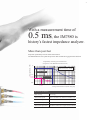
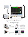
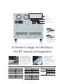
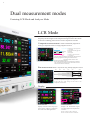
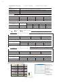
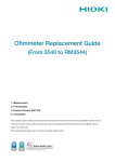
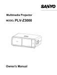
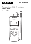
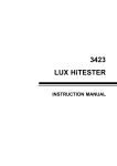
IMPEDANCE ANALYZER IM7580
Component measuring instruments
300 MHz
World’s
fastest
*
Speed up cycle times and accelerate productivity with
high-speed measurement and superior repeatability
*Among impedance analyzers with a frequency bandwidth of 1 MHz to 300 MHz.
2
3
With a measurement time of
0.5 ms, the IM7580 is
history’s fastest impedance analyzer.
More than just fast
Improved repeatability ensures stable measurement.
Repeatability (Z, 3 CV)
The IM7580 delivers the speed and precision that manufacturing applications demand.
Repeatability and analog measurement times
(Comparison of the IM7580 and the Hioki 3535)
1%
Sample: 600 Ω Beads
Measurement frequency: 100 MHz
1/10 the variability
0.1%
Precision
0.046%
0.01%
3535
Faster speed
IM7580
0.1
As fast
as 0.5 ms
1
10
100
1000
Analog measurement time (index time) [ms]
IM7580 basic specifications
Basic accuracy
±0.72% rdg.
Measurement speeds*1
FAST: 0.5 ms / MED: 0.9 ms / SLOW: 2.1 ms / SLOW2: 3.7 ms
Measurable range
100 mΩ to 5 kΩ
Measurement frequency
1 MHz to 300 MHz
Measurement signal level
-40.0 dBm to +7.0 dBm / 4 mV to 1,001 mV / 0.09 mA to 20.02 mA
*1
Analog measurement time
4
268 mm (10.55 in)
215 mm (8.46 in)
IM7580 external view
24 mm (0.94 in)
200 mm
(7.87 in)
55 mm
(2.17 in)
61 mm (2.40 in)
Superior productivity in
a small package
Compact, half-rack
footprint
A test head that fits in
the palm of your hand
The ability to fit two instruments
into a single rack and use them
simultaneously lets you carry out a
variety of measurements faster. This
size is essential for boosting volume
on production lines.
The IM7580’s test head is small
enough to fit in the palm of your
hand, enabling it to be placed closer
to the measurement target. The
ability to position the test head next
to the measured object makes testing
less susceptible to noise and other
adverse effects, increasing accuracy.
Turntable
Fixture
Large display
The display’s brightness, color, and
text size can be changed according to
the needs of your application, while
the touch screen provides a
convenient and intuitive user
experience.
Number of display
digits (3/4/5/6)
Absolute value
display
Customizable
display color
(Background color
and display color)
Customizable
text size
5
1. GP-IB
2. RS-232C
3. EXT I/O
(Handler interface)
4. LAN
5. USB (for PC connectivity)
GP-IB INTERFACE Z3000
RS-232C INTERFACE Z3001
* The GP-IB and RS-232C
INTERFACE are optional.
Extensive range of interfaces
for PC-based management
Save measurement
conditions and results
on a USB flash drive
Extensive range of
interfaces for
external control
Use the USB slot on the front of the
IM7580 to store measurement results,
screens, and measurement conditions
saved on the instrument’s internal
memory on a USB flash drive.
Use the IM7580’s LAN, USB, GP-IB,
RS-232C, and EXT I/O interfaces to
control the instrument from an
external device.
LAN
*The GP-IB and RS-232C interfaces are optional.
GP-IB (optional)
EXT I/O
Connector
RJ-45 connector
Connector
24-pin
Transmission
method
10Base-T, 100Base-Tx,
1000Base-T
Standard
IEEE 488.1 1987
Protocol
TCP/IP
Reference standard
IEEE 488.2 1987
Terminator
CR+LF, LF
USB (for PC connectivity)
RS-232C (optional)
Connector
USB Type B
Connector
D-sub 9-pin
Electrical
specifications
USB 2.0 (High Speed)
Flow control
Software
Transmission speed
9600 / 19200 / 38400 /
57600 bps
Connector
D-sub 37-pin
Female #4-40 inch thread
DC-37P-ULR (solder)
Compatible
connectors
DCSP-JB37PR (crimp)
Japan Aviation Electronics
Industry, Ltd.
*For more information, see page 15.
6
Dual measurement modes
Featuring LCR Mode and Analyzer Mode
LCR Mode
Use LCR Mode to make measurements by applying the desired
frequency and level signal to the component being measured. This mode
is ideal for evaluating passive devices such as capacitors and coils.
Comparator measurement: Yields a PASS/FAIL judgment for
the target component based on a single judgment criterion.
HI
Upper limit
Greater than or equal to upper limit
HI is displayed.
IN
Reference
value
Within range defined by upper and
lower limits
IN is displayed.
LO
Lower
limit
Less than or equal to lower limit
LO is displayed.
Upper and lower limit judgment: Set the upper and lower limits.
Percentage judgment:Set the upper and lower limits as
percentages of the reference value.
Deviation percentage judgment:
Set the upper and lower limits as percentages of the reference
value. The instrument will display deviation of the measured
value from the reference value (Δ%).
Bin measurement: Ranks components using multiple judgment criteria.
BIN1
BIN2
BIN3
BIN4
IN
BIN5
....
BIN10
Measurement
standard range
Set upper and lower limits for each bin. The instrument
will rank components using up to 10 categories.
*Upper and lower limit settings are the same as for
comparator measurement.
Display
Zoom function
Monitor function
Displays measured values using larger
text for better visibility on production
lines and in other field applications.
Displays the measurement signal
level being applied to components in
real time.
Monitor voltage: 0.0 mV to 1000.0 mV
Monitor current: 0.000 mA to 20.000 mA
7
Measurement parameters: Measure up to four parameters simultaneously.
Z
Impedance
G
Conductance
Rp
Equivalent parallel resistance
Cp
Equivalent parallel capacitance
Y
Admittance
B
Susceptance
Ls
Equivalent series inductance
D
Loss factor tan δ
θ
Phase angle
Q
Q-factor
Lp
Equivalent parallel inductance
V
Monitor voltage*
X
Reactance
Rs
Equivalent series resistance (ESR)
Cs
Equivalent series capacitance
I
Monitor current*
*Analyzer mode only
Analyzer Mode
Use Analyzer Mode to perform measurement while sweeping through a
range of measurement frequencies and measurement signal levels. This
mode is ideal for checking frequency characteristics and level characteristics.
Normal/segment sweep operation: Discover component
characteristics by sweeping through a range of frequencies and levels.
Normal
Segment
Sweep parameters
Performs measurement after you set
the sweep parameter (frequency or
level), sweep range, number of sweep
points, and measurement conditions.
Allows you to set the sweep parameter,
sweep range, number of sweep points,
and measurement conditions on a
segment-by-segment basis.
Frequency/signal level (power, voltage, current)
Sweep range
1 MHz to 300 MHz, -40.0 dBm to +7.0 dBm
Number of sweep points/segments
Up to 801 points / Up to 20 segments (with a total of 801 points)
Measurement condition settings
Frequency, level, speed, average
Interval sweep operation: Discover element characteristics over
time under set conditions.
Measurement condition settings
Frequency, level, speed, average
Time interval
0 sec. to 1,000 sec.
Number of sweep points/segments
Up to 801 points / Up to 20 segments (with a total of 801 points)
Display
The graph display can be switched based on
the type of measurement being performed
(with a total of 7 layouts available).
Sweep graph display (1-graph/4-graph display)
XY graph display (1-graph/2-graph display)
Multi-display (simultaneous display of sweep and XY)
List display
Peak display
8
Intelligent measurement and analysis
Convenient functionality for performing measurement, reviewing measurement results,
and judging measured values
Analyzer Mode
LCR Mode
C
A
A
B
C
B
C
B
A: Panel numbers set for continuous measurement; B: Measured values;
C: Parameter judgment results
A: Cursor; B: Search result point; C: Measured values at result point
Continuous
measurement function
Measured value search
function
Conduct continuous measurement by
progressively loading multiple sets of previously
saved measurement conditions using the panel
save function. Measurements can combine LCR
and Analyzer Mode measurement conditions.
The cursor can be moved automatically to a
user-selected measured value point for one set
of sweep measurement results.
Continuous measurement can be performed using up
to 46 measurement condition combinations, and can
be implemented from EXT I/O.
Selecting an Analyzer Mode
panel displays the waveform.
Search options
Maximum value
Moves the cursor to the maximum value.
Minimum value
Moves the cursor to the minimum value.
Target
Moves the cursor to a user-set measured
value.
L-Max value
Moves the cursor to the local maximum
value (a filter can be set).
L-Min value
Moves the cursor to the local minimum
value (a filter can be set).
Select a measurement parameter to search for.
Select the search type.
(If target, enter the value.)
Select whether to search for a rising waveform or
falling waveform.
Panel save and load function
Save previously configured measurement
conditions, compensation values, and
compensation conditions in LCR or Analyzer
Mode and load saved measurement conditions.
Number of panels that can be saved
LCR Mode measurement conditions
30
Analyzer Mode measurement conditions
16
Select whether to use a filter.
(Local maximum and local minimum values only)
Auto search function
Move the cursor automatically according to
user-configured settings once sweep
measurement is complete.
9
A
Area judgment screen
A: Analysis results
Peak judgment screen
Area and peak
comparison functions
Equivalent circuit
analysis function
Check whether measured values fall inside a
previously configured judgment area. These
functions are ideal for use in verifying nondefective products.
Analyze individual component values (L/C/R) for
elements in the following five circuits based on
measurement results:
R1
C1
Area judgment: Obtaining an overall
judgment for each sweep
L1
L1
L1
Define a range by setting upper and lower limits
and display the judgment results as IN or NG.
C1
Peak judgment: Identifying resonance
points
Define a range by setting upper, lower, left, and right
limits and display the judgment results as IN or NG.
R1
R1
L1
IN judgment: Inside area NG judgment: Outside
area
R1
C1
L1
Judgment area
C1
C1
R1
Simulation function/
residual error display
Perform a simulation based on equivalent circuit
analysis results and compare the results to
measured values to verify their accuracy. The
residual error display allows you to check the
quantitative difference between measured values
and simulation results.
Judgment area
Difference
Z
IN judgment: Inside area
NG judgment: Outside
area
Measured values
Simulated values
Frequency
10
Absolute accuracy
The IM7580 features the functionality you need to make accurate, reliable measurements.
Contact check
Compensation function
The instrument checks the state of contact between
the measurement terminals and circuit elements to
verify the state of contact and detect contact errors.
To truly measure accurately, all analyzers
should first be set up to their optimal state.
DCR measurement: Checking contact before
Test head terminals
(Calibration reference
surface)
and after measurement
This capability is ideal for carrying out contact checks of inductive
components with low DC resistance values such as inductors,
ferrite cores, and common-mode filters.
Judgments based on user-configured upper and lower contact resistance limits
Guaranteed accuracy range
0.1 Ω to 100 Ω
Measurement timing
Before measurement, after measurement, or before and after measurement
Measured value > Upper limit: Displays “HI.”
Upper limit ≥ Measured value ≥ Lower limit: Displays “IN.”
Measured value < Lower limit: Displays “LO.”
Sample connection
terminals
(Calibration reference
surface)
Measurement
sample
1 m cable (optional: 2 m)
Connector/cable/test fixture
Test head
IM7580
Open, short, and load calibration
Hi-Z reject function: Judging the contact state
based on measurement results
The compensation process involves calibrating the measurement
setup, from the IM7580 to the reference surface (either the test
head terminals or the sample connection terminals).
Each of three standards (open, short, and load) is connected and its
calibration data measured to eliminate potential sources of error.
Activate this function in order to output a measurement terminal
contact error if the impedance measured value is greater than a
user-configured reference value.
Electrical length compensation
Valid setting range
1 Ω to 10000 Ω
Enter the length of the electrical connection between the reference
surface and the measurement sample connection surface to allow
compensation of error caused by phase shift.
Waveform judgment function: Detecting
If mounting a fixture on the test head, it is necessary to enter the fixture’s electrical
Verify that components and terminals are in contact during
measurement. The instrument will output an error if fluctuations in
the RMS value exceed a user-configured range that has been set using
the initially acquired RMS value waveform as the reference value.
Open and short compensation
chatter during measurement
Valid setting range
0.01% to 100.0% of the reference value
Output format
Screen error display or EXT I/O error output
length.
Open and short compensation eliminates sources of error from
the calibration reference surface to the sample connection
surface (including the fixture, measurement cables, etc.).
11
1
A
TRIG
B
EOM
EOM
2
Reset on
ERR
Reset off
Previous
Current
Previous
Current
TRIG
3
EOM
A
Pulse
A
Delay
B
Previous
ERR
4
Hold
Current
INDEX
Signal
External control I/O
Key lock function
When using external control, you can regulate
the input and output signal timing as desired.
You can lock the instrument’s keys to prevent
erroneous or unauthorized screen operation.
1. Trigger input:
Timing and enable/disable settings
A.Choose to enable or disable trigger input during measurement. By
disabling input, you can prevent erroneous input caused by chatter.
Full key lock
Disables all setting changes.
Set key lock
Enables only comparator and bin
judgment settings.
*Before activating the key lock function, check the passcode setting.
B.Select whether to base input timing on the trigger’s rising edge or
falling edge.
2. Reset
Audio Signal
judgment result
You can set the timing at which judgment results are reset.
On: Reset the previous judgment results at the measurement
complete signal’s rising edge.
Off:Reset the previous judgment results when the next judgment
results are output.
3. Measurement complete signal:
Output method and output delay
A.Select whether to use pulse or hold output for the measurement
complete signal.
Pulse:You can set the duration for which the measurement
complete signal is placed in the “on” state.
Hold: The measurement complete signal switches from “on” to
“off” at trigger input.
B.You can set the duration of the delay from output of judgment
results to output of the measurement complete signal.
4. Analog measurement
Output delay
signal:
When using trigger-synchronized output, you can ensure that the
analog measurement signal is only output once the measurement
signal has turned off.
Trigger-synchronized output: The measurement signal is only
applied to the sample during measurement.
You can turn the beep tone on or off based on
the comparator judgment results.
The key tone can also be turned on or off.
Beep types: 14
Volume: 3 settings
Warm-up function
The instrument will display a message
indicating that warm-up operation is complete
about 60 minutes after it is powered on.
(A warm-up period of 60 minutes is required in order for
the instrument to perform at its defined accuracy.)
12
Applications
Common-mode filter measurement
Panel save and continuous measurement
When one component must be measured two different ways or when compensation values and measurement conditions differ
for each measurement point, the IM7580 streamlines the measurement process by automatically switching among compensation
values and measurement conditions.
When one component must be measured two different ways
Automatic
switching
Common mode
Differential mode
Halve cycle times by using two instruments…
Thanks to a compact design, two IM7580s can be stored in one
rack. Using two impedance analyzers simultaneously can
dramatically reduce cycle times.
When compensation values and measurement conditions differ for each
measurement point
4
3
2
1
Progressive switching of
compensation values and
measurement conditions
1→2→3→4
PASS/FAIL judgments for power inductors
Comparator function
By using the comparator function’s area and peak judgment functions, you can easily differentiate between defective and
non-defective components.
Set the judgment area and then check whether component
measurement results fall inside that area. This approach
is well suited to differentiating between defective and
non-defective components.
Non-defective: IN
Defective: NG
As illustrated to the left, you can
set a range around the peak value
and use it to make judgments.
Area judgment
13
Measurement parameters and measurement conditions
Z
Y
θ
X
G
B
Q
Measurement
parameters
Display range
Z
Y
θ
X
G
B
Q
Impedance
Admittance
Phase angle
Reactance
Conductance
Susceptance
Q-factor
Rs
Rp
Ls
Lp
Cs
Cp
D
Equivalent series resistance (ESR)
Equivalent parallel resistance
Equivalent series inductance
Equivalent parallel inductance
Equivalent series capacitance
Equivalent parallel capacitance
Loss factor tan δ
0.00m to 9.99999G Ω
0.000n to 9.99999G S
±(0.000° to 999.999°)
±(0.00m to 9.99999G Ω)
±(0.000n to 9.99999G S)
±(0.000n to 9.99999G S)
±(0.00 to 9,999.99)
Rs
Rp
Ls
Lp
Cs
Cp
D
Δ%
±(0.00m to 9.99999G Ω)
±(0.00m to 9.99999G Ω)
±(0.00000n to 9.99999G H)
±(0.00000n to 9.99999G H)
±(90.00000p to 9.99999G F)
±(0.00000p to 9.99999G F)
±(0.00000 to 9.99999)
±(0.000 to 999.999%)
Measurable range
100 mΩ to 5 kΩ
Output impedance
50 Ω (at 10 MHz)
Measurement
frequency
Measurement
signal level
Range
1 MHz to 300 MHz
Resolution
1.0000 MHz to 9.9999 MHz: 100 Hz steps
10.000 MHz to 99.999 MHz: 1 kHz steps
100.00 MHz to 300.00 MHz: 10 kHz steps
Accuracy
±0.01% of setting or less
Range
Power: -40.0 dBm to +7.0 dBm
Voltage: 4 mV to 1,001 mV
Current: 0.09 mA to 20.02 mA
User-configured power, voltage, and current
Resolution
0.1 dB steps
Accuracy
±2 dB (23°C ±5°C) / ±4 dB (0°C to 40°C)
Speed and accuracy
Measurement speed
(analog
measurement)
Averaging
Basic accuracy
Guaranteed
accuracy range
Guaranteed
accuracy period
Terminal design
FAST
MED
: 0.5 ms
: 0.9 ms
SLOW
SLOW2
: 2.1 ms
: 3.7 ms
Valid setting range: 1 to 256 (in steps of 1)
Z: 0.72% rdg. θ: 0.41°
100 mΩ to 5 kΩ (impedance)
1 year
2-terminal design
Supplementary functionality
Trigger function
Compensation
function
Contact check
*1
User-selectable internal or external trigger (EXT I/O,
interface, manual)
Trigger delay: 0 sec. to 9 sec.
Trigger-synchronized output: Stabilization wait time of 0
sec. to 9 sec.
INDEX signal delay time of 0 sec. to 0.1 sec.
Trigger types: Sequential, repeat, step*1
Open/short/load calibration: From IM7580 to test head
Open/load compensation: Compensation of fixture
component
Electrical length compensation: 0 mm to 100 mm
Correlation compensation: Compensation of display values
based on user-input compensation coefficient
DCR measurement, Hi-Z reject function, waveform
judgment function
Analyzer mode only
Recording and interface
Measurement modes
Measurement modes
LCR mode: Measurement using a single set of conditions
Analyzer mode: Sweep measurement and equivalent circuit
analysis
Continuous measurement mode: Continuous measurement
using previously saved conditions
LCR mode
Bin measurement: 10 categories for 4 measurement parameters
Measurements
Comparator measurement: Hi, IN, and Lo judgments for 4
parameters
Functionality
Monitor function
Monitor voltage range: 0.0 mV to 1000.0 mV
Monitor current range: 0.000 mA to 20.000 mA
Display
Zoom display function: Enlarged display of measured values
Analyzer mode
Measurements
Functionality
Display
Display and sound
Key lock function
Beep tone
Warm-up function
Selection of number
of display digits
Display settings
Sweep measurement
Up to 801 sweep points with user-configurable point delay
Normal sweep: Measurement of up to 801 points
Segment sweep: Up to 20 segments (with a total of 801
points)
Display
Time interval measurement
Interval of 0.00000 sec. to max. 1,000.00 sec., 801 points
Other
Equivalent circuit analysis: 5 circuit models
Cursor function: Automatically search for maximum and
minimum values, target, local maximum and minimum
values
Comparator function: Area and peak judgment
List display graph display, XY graph display, judgment
results display
Scaling: Linear or logarithmic
Continuous measurement mode
Measurements
LCR Mode: 32000
Number of measured
Analyzer Mode: 100 sweeps
values that can be
Measured values are stored in the instrument and then saved
stored in memory
all together.
Measurement conditions: 30 sets for LCR mode, 16 sets for
Panel save and load
Analyzer mode
functions
Compensation values only: 30 sets for LCR mode
HANDLER, USB, LAN, GP-IB (optional), RS-232C
Interfaces
(optional)
Continuous measurement using up to 46 combinations of the
following measurement conditions:
30 LCR mode measurement conditions and 16 analyzer
mode measurement conditions
Operating
temperature and
humidity range
Storage temperature
and humidity range
Operating
environment
Power supply and
maximum rated
power
Dielectric strength
Standards compliance
Dimensions and
weight
Accessories
Lock operation of the instrument using the panel. Unlock by
entering a passcode.
Enable or disable for judgment results and key operation.
The instrument will display a message 60 minutes after it is
powered on.
3, 4, 5, or 6 digits
LCD display on/off
Backlight brightness adjustment
Measurement screen background color (white or black)
Switchable parameter colors
8.4-inch color TFT with touch panel
0°C to 40°C, 20% RH to 80% RH, non-condensing
-10°C to 50°C, 20% RH to 80% RH, non-condensing
Use indoors at an elevation of 2,000 m or less in an
environment with a maximum pollution level of 2.
100 V to 240 V AC (50/60 Hz), 70 VA
1.62 kV AC for 1 min. between power line and ground line
EMC: EN 61326, EN 61000
Safety: EN 61010
Approx. 215 W × 200 H × 268 D mm (8.46 W × 7.87 H ×
10.55 D in) , approx. 6.5 kg (229.3 oz)
Test head ×1, Connection cable ×1, Power cord ×1, Instruction
manual ×1, LCR application disc (Communications user manual) ×1
14
Measurement accuracy
Z: ±(Ea + Eb) [%]
θ: ±0.58 × (Ea + Eb) [°]
Conditions
Guaranteed accuracy temperature
and humidity range
0°C to 40°C, 20% RH to 80% RH (non-condensing)
However, must be within ±5°C of the temperature at the time of calibration.
Guaranteed accuracy period
1 year (Open, short, and load calibration should be performed daily before measurement.)
Warm-up time
At least 60 min.
Measurement conditions
Frequency, power, and speed points at which open, short, and load calibration have been performed
Ea = 0.5 + Er
Er: For power of -7 dBm to +7 dBm
Frequency
FAST
MED
SLOW
SLOW2
1 MHz to 100 Mhz
0.09
0.06
0.036
0.03
100.01 MHz to 300 MHz
0.108
0.078
0.039
0.036
Er: For power of -40 dBm to -7.1 dBm
Eoff
Frequency
Er
FAST
MED
SLOW
SLOW2
1 MHz to 100 MHz
3 × 10 (-0.046P + Eoff)
-1.8
-2
-2.15
-2.3
3 × 10
-1.75
-1.9
-2.1
-2.25
100.01 MHz to 300 MHz
(-0.048P + Eoff)
P: Power setting [dBm]
)
Eb =
(
Zs =
( 20 + Zsr + 0.5 × F )
[Ω] ( F: Measurement frequency [MHz] )
1000
Zs
+ Yo· Zx
Zx
× 100 [%] ( Zx :Z measured value in [Ω])
Zsr: For power of -7 dBm to +7 dBm
FAST
MED
SLOW
SLOW2
13.5
9
5.1
3.9
Zsr: For power of -40 dBm to -7.1 dBm
Zoff
Zsr
3 × 10
(-0.048P + Eoff)
FAST
MED
SLOW
SLOW2
0.35
0.2
0
-0.15
P: Power setting [dBm]
Yo =
( 30 + Yor + 0.15 × F )
[S] ( F: Measurement frequency [MHz] )
1000000
Yor: For power of -7 dBm to +7 dBm
FAST
MED
SLOW
SLOW2
7.5
5.7
3.3
2.4
Yor: For power of -40 dBm to -7.1 dBm
Zoff
Yorr
3 × 10
(-0.046P + Yoff)
FAST
MED
SLOW
SLOW2
0.1
0
-0.2
-0.4
P: Power setting [dBm]
Basic measurement confirmation table*
Free software for
calculating accuracy
Z [Ω]
1000
100
10
0.8 %
1%
2%
5%
10 %
1
1
10
100
Measurement frequency [MHz]
*For -7 dBm to +7 dBm, SLOW2.
Free software for
automatically
calculating
measurement accuracy
based on user-entered
measurement
conditions and
measurement results
can be downloaded
from Hioki’s website.
15
External control
List of EXT I/O handler interface signals
19 18 17 16 15 14 13 12 11 10
9
8
7
6
5
4
3
Pin
I/O
1
IN
TRIG
2
IN
Unused
3
IN
Unused
4
IN
LD1
5
IN
LD3
TRIG
External trigger
6
IN
LD5
LD0 to LD6
Panel number selection
7
IN
Unused
8
-
ISO_5V
EOM
Measurement complete signal
ISO_COM
INDEX
Analog measurement complete signal
Detection level error
2
1
Signal
37 36 35 34 33 32 31 30 29 28 27 26 25 24 23 22 21 20
Signal
Function
9
-
10
OUT
ERR
ERR
11
OUT
PARA1-HI,BIN1,PARA1-NG
LD_VALID
Panel load
12
OUT
PARA1-LO,BIN3,PARA2-NG
13
OUT
PARA2-IN,BIN5,PARA3-NG
ISO_5V
Isolated power supply 5 V input
14
OUT
AND,BIN7
ISO_COM
Isolated power supply common
Comparator judgment result: HI judgment
15
OUT
PARA3-IN,BIN9,PARA4-IN
PARA1-HI to PARA4-HI
16
OUT
PARA4-HI
PARA1-IN to PARA4-IN
Comparator judgment result: IN judgment
17
OUT
PARA4-LO
18
OUT
Unused
PARA1-LO to PARA4-LO
Comparator judgment result: LO judgment
19
OUT
OUT_OF_BINS,CIRCUIT_NG
OUT_OF_BINS
Bin measurement result
20
IN
Unused
BIN1-BIN10
Bin judgment allocation: Bin 1 to Bin 10
CIRCUIT_NG
Equivalent circuit analysis: Comparator judgment result
PARA1-NG to PARA4-NG
Peak judgment result
PARA1-IN to PARA3-IN
Peak judgment result
AND
Result of applying a logical AND operation to judgment
results for measured values for four parameters (output
when all judgment results are IN)
21
IN
Unused
22
IN
LD0
23
IN
LD2
24
IN
LD4
25
IN
LD6
26
IN
LD_VALID
ISO_COM
27
-
28
OUT
EOM
29
OUT
INDEX
30
OUT
PARA1-IN,BIN2,PARA1-IN
31
OUT
PARA2-HI,BIN4,PARA2-IN
32
OUT
PARA2-LO,BIN6,PARA3-IN
Connector
used
33
OUT
PARA3-HI,BIN8,PARA4-NG
34
OUT
PARA3-LO,BIN10,
35
OUT
PARA4-IN
36
OUT
Unused
37
OUT
Unused
D-sub 37-pin
Female #4-40 inch thread
Input
signals
Electrical
Output
specifications signals
DC-37P-ULR (solder)
Compatible
DCSP-JB37PR (crimp)
connectors
Japan Aviation Electronics Industry, Ltd.
Photocoupler-isolated, no-voltage contact input
Input “on” voltage: 0 V to 0.9 V / input “off” voltage: open or 5 V to 24 V
Isolated NPN open collector output
Maximum load voltage: 30 V / maximum output current: 50 mA/channel
Residual voltage: 1 V or less (10 mA) or 1.5 V or less (50 mA)
Built-in isolated Voltage: 4.5 V to 5 V / maximum output current: 100 mA
power supply
Floating relative to protective ground potential and measurement circuit
Timing chart
Example of LCR Mode measurement timing
TRIG
(Measurement
start signal)
EOM
(Measurement
complete signal)
Chuck
OFF
ON
ON
ON
Previous
ERR judgment result
(Error signal)
OFF
OFF
TRIG
(Measurement
start signal)
(Judgment result output)
Judgment result
LD_VALID
LD0 to LD6
LD0 to LD6
*In this example, the TRIG signal’s active edge is the falling edge (ON).
ON
ON
ON
Previous
ERR judgment result
(Error signal)
LD_VALID
Chuck
OFF
ON
INDEX
(Analog measurement
complete signal)
ON
Open
Chuck
Connection state
EOM
(Measurement
complete signal)
ON
INDEX
(Analog measurement
complete signal)
(Judgment result output)
Open
Chuck
Connection state
Example of Analyzer Mode measurement timing
OFF
ON
Judgment result
EOM: Off from trigger input to end of measurement processing
INDEX: Off during probe chuck (probe cannot be removed from target)
OFF
Instrument
IMPEDANCE ANALYZER IM7580
IMPEDANCE ANALYZER IM7580-02
Standard accessories*1
• Test head
• Connection cable (IM7580: 1 m / IM7580-02: 2m)
• Instruction manual
• LCR application disc (Communications user manual)
• Power cord
Free software for calculating
accuracy
(LCR application disc)
Free software for automatically
calculating measurement accuracy
based on user-entered measurement
conditions and measurement results
can be downloaded from Hioki’s
website.
*1 The instrument does not ship with a test fixture or probe. A test fixture designed
specifically for use with the Impedance Analyzer IM7580 is required. For more
information, please contact your Hioki distributor.
Options
Interfaces
GP-IB INTERFACE Z3000
GP-IB CONNECTION CABLE 9151-02
Cable length: 2 m (6.56 ft)
RS-232C INTERFACE Z3001
RS-232C CABLE 9637
Cable length: 1.8 m (5.91ft)
Any interlink-compatible cross-cable can be used as the RS-232C CABLE.
Test fixtures and associated options: Available in December 2014 (tentative)
• TEST FIXTURE STAND IM9200
• ADAPTER IM9906 (3.5 mm to 7 mm)
• SMD TEST FIXTURE IM9201
Note: Company names and Product names appearing in this catalog are trademarks or registered trademarks of various companies.
HIOKI (Shanghai) SALES & TRADING CO., LTD.:
TEL +86-21-63910090 FAX +86-21-63910360
http://www.hioki.cn / E-mail: [email protected]
DISTRIBUTED BY
HIOKI INDIA PRIVATE LIMITED:
TEL +91-124-6590210 FAX +91-124-6460113
HEADQUARTERS:
E-mail: [email protected]
81 Koizumi, Ueda, Nagano, 386-1192, Japan
TEL +81-268-28-0562 FAX +81-268-28-0568 HIOKI SINGAPORE PTE. LTD.:
http://www.hioki.com / E-mail: [email protected] TEL +65-6634-7677 FAX +65-6634-7477
E-mail: [email protected]
HIOKI USA CORPORATION:
HIOKI KOREA CO., LTD.:
TEL +1-609-409-9109 FAX +1-609-409-9108 TEL +82-42-936-1281 FAX +82-42-936-1284
http://www.hiokiusa.com / E-mail: [email protected] E-mail: [email protected]
All information correct as of Sept. 10, 2014. All specifications are subject to change without notice.
IM7580E2-49B
Printed in Japan