1
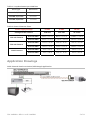
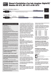
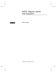
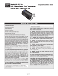
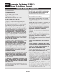
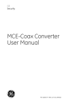
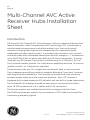
GE
Security
Multi-Channel AVC Active
Receiver Hubs Installation
Sheet
Introduction
GE Security Multi-Channel AVC Active Receiver Hubs are advanced devices that
feature Automatic Video Compensation (AVC) technology. AVC incorporates a
sophisticated microprocessor controlled analog circuit that continuously
analyzes incoming video signals and compensates for cable attenuation
independent of video signal content. It provides high-resolution color or black
and white video over unshielded twisted pair wires of category 2-7, at distances
up to 6,000 feet (1,830 m) when used with any GE Active Transmitter. It can be
used with any GE Passive Transceiver for distances up to 3,500 feet (1,067 m).
The 8 channel models provide 1 to 4 distribution amplifiers while the 16 channel
models include 1 to 2 distribution amplifiers.
These receiver hubs are 1U in height and can be wall, desk or rack mounted.
Their integrated ground loop isolation prevents disturbing "hum-bars" common
with long distance installations. Their excellent crosstalk and noise immunity
provides quality video up to the maximum distance. Each UTP channel is
equipped with a video presence LED indicator and has built-in surge suppression.
The included RJ-45 adapters provide an easy way to connect active hubs to
other GE VPD products via Cat-5 cables and RJ-45 connectors.
The Active receivers are unidirectional and do not support Up-the-Coax
Pan/Tilt/Zoom telemetry signals. Any unused pair of UTP cable can be used for
transporting telemetry signals.
1 of 11
© 2010 GE Security, Inc.
P/N 1069681 • REV 1.0 • ISS 14APR10
The following model numbers are covered in this document:
•
GEC-4VARHUB-4
•
GEC-8VARHUB-4
•
GEC-16VARHUB-4
•
GEC-32VARHUB-4
•
GEC-8VARHUB-6.5
•
GEC-16VARHUB-6.5
•
GEC-32VARHUB-6.5
Important Safety Warnings
•
Installation should be made by a qualified service person and should
conform to all local codes.
•
DO NOT bundle UTP signals in the same conduit as high-voltage wiring.
•
To reduce the risk of fire or electrical shock, do not expose these products to
rain, moisture, dripping or splashing.
•
No objects filled with liquids, such as vases, shall be placed on GE equipment.
•
DO NOT block ventilation openings to let sufficient airflow to the UTP devices.
•
The Main fuse for models with built-in AC power supply is 5 A at 110 VAC or
at 3 A 220 VAC. Each camera power fuse is 2 A and can be accessed by
removing the front panel. Fuses may be replaced by a qualified service
person only when the unit is off and AC power cord is unplugged.
•
Use only the power cord and plug supplied with the unit for connecting to AC
outlets.
•
Only unplugging the power cord is considered as a main power disconnect.
•
DO NOT connect multiple outputs together.
•
Make sure that the mains Voltage input is set to the proper local voltage.
2 of 11
P/N 1069681 • REV 1.0 • ISS 14APR10
IMPORTANT IMPORTANT
SAFETY INSTRUCTIONS
SAFETY INSTRUCTIONS
1) Read these instructions.
2) Keep these instructions.
3) Heed all warnings.
4) Follow all instructions.
5) Do not use this apparatus near water.
6) Clean only with a dry cloth.
7) Do not block any ventilation openings.
8) Install in accordance with the manufacturer’s instructions.
9) Do not install near any heat sources such as radiators, heat registers, stoves or other
apparatus (including DVRs) that produce heat.
10) Do not defeat the safety purpose of the polarized or grounding-type plug. A polarized plug
has two blades with one wider than the other. A grounding type plug has two blades and a
third grounding prong. The wider blade or the third prong are provided for your safety. If the
provided plug does not fit into your outlet, consult an electrician for replacement of the
obsolete outlet.
11) Protect the power cord from being walked on or pinched particularly at plugs, convenience
receptacles, and the point where they exit from the apparatus.
12) Only use attachments/accessories specified by the manufacturer.
13) Unplug this apparatus during lightning storms or when unused for long periods of time.
14) Refer all servicing to qualified service personnel. Servicing is required when the apparatus
has been damaged in any way, such as a power supply cord or plug is damaged, liquid has
been spilled, or objects have fallen into the apparatus, the apparatus has been exposed to
rain or moisture, does not operate normally, or has been dropped.
CAUTION
RISK OF ELECTRIC SHOCK
DO NOT OPEN
CAUTION: TO REDUCE THE RISK OF ELECTRICAL SHOCK,
DO NOT REMOVE COVER. NO USER SERVICEABLE
PARTS INSIDE. REFER SERVICING TO QUALIFIED
SERVICE PERSONNEL.
WARNING! - To reduce the risk of fire or electric shock, do not expose this apparatus to
rain or moisture. This apparatus shall not be exposed to dripping or splashing and no objects
filled with liquids, such as vases shall be placed on the apparatus.
WARNING! - This apparatus is a Class I product. This product must be connected to a
mains socket outlet with a
protective earthing connection.
WARNING! - The mains plug is used as the disconnect device and shall remain readily
operable.
The lightning flash with arrowhead symbol, within an equilateral triangle, is intended to alert the user to the presence of uninsulated
"dangerous voltage" within the product's enclosure that may be of sufficient magnitude to constitute a risk of electric shock to persons.
The exclamation point within an equilateral triangle, is intended to alert the user to the presence of important operating and
maintenance instructions in the literature accompanying the appliance.
P/N 1069681 • REV 1.0 • ISS 14APR10
3 of 11
Wiring Technical Notes
These technical notes should all be considered prior to installing these devices.
•
Use point to point unshielded twisted pair wire 24-16 AWG (0, 5-1, 3 mm)
stranded or solid, Category 2 or better.
•
The video signal may coexist in the same wire bundle as other video,
telephone, data, control signals, or low-voltage power. You can run GE video
signals in or near electromagnetic fields (in accordance with National
Electrical Code, local or other local safety requirements).
•
DO NOT USE SHIELDED TWISTED PAIR WIRE. Multi-pair (8 pair or more) wires
with an overall shield are fine.
•
DO NOT USE UN-TWISTED WIRE.
•
DO NOT place a transmit and a receive signal in the same wire bundle. It
may cause interference.
•
DO NOT send Up-the-Coax Pan/Tilt/Zoom signals through active (amplified)
GE transmitters or receivers. Passive GE transceivers can transmit video and
Up-the-Coax P/T/Z control signals up to 750 ft. (228 m).
•
We recommend using short 18 AWG solid wires for ground connections.
•
GE VPD products follow the EIA/TIA 568 standard. There are two wire colorcode standards: EIA/TIA 568A and EIA/TIA 568B. Either standard can be used
for making connections as long as the RJ-45 jacks at both ends of each
cable follow the same standard.
•
Measure wire distance by:
1.
Shorting the two conductors together at the far end, and measuring
the loop-resistance by an Ohmmeter.
2.
Use the Loop Resistance table to calculate the distance.
•
DO NOT connect coax cables longer than 100 ft. (30 M) to the BNC
connectors of any GE UTP equipment.
•
All measured distances should include any coax cables in the path.
•
Verify camera current requirements and wire resistance limits for the
maximum distance that power can travel. Use the Power Distance Chart to
verify the wire distance.
•
GE VPD products require Unshielded Twisted-Pair (UTP) wires Category 2 or
better, 24 AWG (0,5 mm) or thicker.
4 of 11
P/N 1069681 • REV 1.0 • ISS 14APR10
Table 1: Loop Resistance per 1000 feet
Wire Type
Resistance
24 AWG /0,53 mm
52 ohms
23 AWG /0,57 mm
42 ohms
22 AWG /0,64 mm
33 ohms
Table 2: Power Distance Chart
Power Supply Voltage
12 VDC
24 VAC
28 VAC
Voltage at the Camera
10.8 VDC
21.6 VAC
21.6 VAC
Dual 24 AWG
448 ft. / 137 m
896 ft. / 273 m
2,388 ft. / 728 m
Dual 23 AWG
564 ft. / 172 m
1,130 ft. / 345 m
3,012 ft. / 918 m
Dual 24 AWG
150 ft. / 46 m
300 ft. / 92 m
796 ft. / 243 m
Dual 23 AWG
190 ft. / 58 m
378 ft. / 115 m
1,004 ft. / 306 m
Dual 24 AWG
46 ft. / 14 m
90 ft. / 28 m
240 ft. / 73 m
Dual 23 AWG
58 ft. / 18 m
114 ft. / 35 m
300 ft. / 92 m
100 mA Camera
300 mA Camera
1 AMP Camera
Application Drawings
Multi-channel Passive to Active (Mid-Range) Application
P/N 1069681 • REV 1.0 • ISS 14APR10
5 of 11
Multi-channel Active to Active (Long-Range) Application
Camera End Installation
Video:
Passive Transceiver
•
Connect the baseband Video signal output of the camera to the BNC of the
GE single-channel passive transceiver.
•
Connect the ground screw connector to a qualified earth ground using a
short thick wire (GEC-PVTC-FCSP, GEC-PVTC-MSP).
•
Connect the UTP to the terminal block of the GE transceiver.
Active Transmitter
•
Connect the baseband video output of the camera to the BNC input of the
GE active transmitter.
•
Connect the UTP to the terminal block of transmitter.
•
Connect the ground screw connector to a qualified earth ground using a
short thick wire.
•
Set the distance switch to the appropriate position based on the measured
camera distance.
Power:
•
Connect a qualified 12 VDC or 24 VAC power supply cable to the
transmitter’s input power terminal block.
6 of 11
P/N 1069681 • REV 1.0 • ISS 14APR10
Control Room Installation
UTP:
•
Connect the UTP wires carrying video signals to the terminal block input of
the receiver hub. If the UTP is terminated with a RJ-45 connector, then use
either the RJ-45 connector or provided RJ-45 adapter to connect to the
transceiver hub.
•
Make sure that the same UTP pair and polarity are used on both transmit
and receive sides.
Video:
•
Use provided 2-foot (60 cm) coax patch cords to connect the BNC video
inputs of video receiving devices such as DVRs or matrix switches.
Power:
GEC-4VARHUB-4
•
Connect the ground screw connector to a qualified earth ground using a
short thick wire.
•
Connect the external power supply cable to the power input connector of the
GEC-4VARHUB-4.
Note: This product is intended to be supplied by a UL Listed Direct Plug-In Power
Unit marked “Class 2” or “LPS” and output rated 12 VDC, 1 Amp minimum.
All other models
•
Connect the AC power cord to a grounded AC power outlet.
•
The receiver hubs do not require any adjustments. They are equipped with
Automatic Video Compensation (AVC) circuit that automatically adjusts the
video quality regardless of video content.
P/N 1069681 • REV 1.0 • ISS 14APR10
7 of 11
•
If the picture is scrambled change the polarity of the twisted pair wires to the
corresponding terminal block.
Technical Specifications*
Electrical
Video Format
NTSC, PAL, SECAM
Frequency
20 Hz to 6 MHz
Adjustment
Automatically controlled by internal microprocessor
Coax
75 Ohm
Twisted Pair
100 Ohms +/- 20%, 24 AWG min., unshielded Category 2-7 up to 750 ft.
(228m)
CMRR
70 dB
Video Present
Green LED’s, one per channel
Power indicator
Red LED
Connectors
UTP inputs: Detachable terminal blocks, RJ-45 or Optional RJ-45 Adapter
(Included)
Video Outputs: BNC
Power: IEC380 AC power inlet (excluding GEC-4VARHUB-4)
Standard P1J DC inlet receptacle 2.1 x 5.5 mm, center positive (GEC4VARHUB-4)
Main AC Fuse
1 A at 115 VAC/3 A at 220 VAC, 5x20 mm, 8 channel models
1.5 A at 115 VAC/5 A at 220 VAC, 5x20 mm, 16 channel models
2 A at 115 VAC/5 A at 220 VAC, 5x20 mm, 32 channel models
A spare fuse is located inside the fuse holder.
Environmental
Humidity
0 to 95%, noncondensing
Temperature
Operating: -10° to +50° C
Storage: -30° to +70° C
8 of 11
P/N 1069681 • REV 1.0 • ISS 14APR10
Model
Number of
Channels
Max. Range
w/Passive TX
Max. Range
with Active TX
Power Supply
Voltage
Power Supply
Current (max.)
GEC-4VARHUB-4
4
2,000 feet
4,000 feet
12 VDC/24 VAC
400 mA
GEC-8VARHUB-4
8
2,000 feet
4,000 feet
80-240 VAC
125 mA
GEC-16VARHUB-4
16
2,000 feet
4,000 feet
80-240 VAC
200 mA
GEC-32VARHUB-4
32
2,000 feet
4,000 feet
80-240 VAC
250 mA
GEC-8VARHUB-6.5
8
3,500 feet
6,000 feet
80-240 VAC
125 mA
GEC-16VARHUB-6.5
16
3,500 feet
6,000 feet
80-240 VAC
200 mA
GEC-32VARHUB-6.5
32
3,500 feet
6,000 feet
80-240 VAC
250 mA
Model GEC-4VARHUB-4:
This product is intended to be supplied by a UL Listed Direct Plug-In Power Unit
marked “Class 2” or “LPS” and output rated 12 VDC, 1 Amp minimum.
Mechanical
Material
GEC-4VARHUB-4: ABS plastic, UL rating of 94V-0
All other models: Extruded Aluminum and sheet metal
Dimensions (W x H x D) GEC-4VARHUB-4: 4.97 x 1.74 x 1.77 in. (12.6 x 4.2 x 4.5 cm)
GEC-8VARHUB-4: 17 x 1.74 x 8 in. (43 x 4.2 x 203 cm)
GEC-16VARHUB-4: 17 x 1.74 x 8 in. (43 x 4.2 x 203 cm)
GEC-32VARHUB-4: 17 x 1.74 x 8 in. (43 x 4.2 x 203 cm)
GEC-8VARHUB-6.5: 17 x 1.74 x 8 in. (43 x 4.2 x 203 cm)
GEC-16VARHUB-6.5: 17 x 1.74 x 8 in. (43 x 4.2 x 203 cm)
GEC-32VARHUB-6.5: 17 x 1.74 x 8 in. (43 x 4.2 x 203 cm)
Weight
GEC-4VARHUB-4: 0.31 lb. (142 g)
GEC-8VARHUB-4: 4.5 lb. (2.04 kg)
GEC-16VARHUB-4: 4.6 lb. (2.09 kg)
GEC-32VARHUB-4: 5.6 lb. (2.54 kg)
GEC-8VARHUB-6.5: 4.5 lb. (2.04 kg)
GEC-16VARHUB-6.5: 4.6 lb. (2.09 kg)
GEC-32VARHUB-6.5: 5.6 lb. (2.54 kg)
*Specifications are subject to change without notice.
P/N 1069681 • REV 1.0 • ISS 14APR10
9 of 11
Included Accessories
(Excluding the GEC-4VARHUB-4)
•
Mounting brackets for front, rear or wall installations
•
Rubber feet for desk applications
•
(8, 16, or 32) 2 ft. (60 cm) coax jumper cables
•
RJ-45 Adapter
•
Molded IEC power inlet cord 7 ft. (200 cm)
EIA/TIA 568A, B Color Codes
10 of 11
P/N 1069681 • REV 1.0 • ISS 14APR10
Regulatory information
Manufacturer
GE Security, Inc.
HQ and regulatory responsibility:
GE Security, Inc., 8985 Town Center Parkway,
Bradenton, FL 34202, USA
EU authorized manufacturing representative:
GE Security B.V., Kelvinstraat 7,
6003 DH Weert, The Netherlands
Regulatory
information
N4131
Note: C-Tick mark applies to model GEC-4VARHUB-4 only.
North American
standards
UL 60065
FCC Compliance
This equipment has been tested and found to comply with the limits for a
Class B digital device, pursuant to part 15 of the FCC Rules. These limits are
designed to provide reasonable protection against harmful interference in a
residential installation. This equipment generates, uses and can radiate
radio frequency energy and, if not installed and used in accordance with the
instructions, may cause harmful interference to radio communications.
However, there is no guarantee that interference will not occur in a
particular installation. If this equipment does cause harmful interference to
radio or television reception, which can be determined by turning the
equipment off and on, the user is encouraged to try to correct the
interference by one or more of the following measures:
•
Reorient or relocate the receiving antenna.
•
Increase the separation between the equipment and receiver.
•
Connect the equipment into an outlet on a circuit different from that to
which the receiver is connected.
•
Consult the dealer or an experienced radio/TV technician for help.
2002/96/EC (WEEE directive): Products marked with this symbol cannot be
disposed of as unsorted municipal waste in the European Union. For proper
recycling, return this product to your local supplier upon the purchase of
equivalent new equipment, or dispose of it at designated collection points.
For more information see: www.recyclethis.info.
Contact information
For contact information see our Web site: www.gesecurity.com.
For contact information see our Web site: www.gesecurity.eu.
P/N 1069681 • REV 1.0 • ISS 14APR10
11 of 11