1
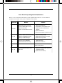
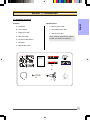
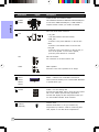
User’s Manual Intel i945P mainboard for Intel Soc ket 775 pr ocessor Sock processor TRADEMARK All products and company names are trademarks or registered trademarks of their respective holders. These specifications are subject to change without notice. Manual Revision 1.0 March 30, 2006 60000125PJ310 DISCLAIMER OF WARRANTIES: THERE ARE NO WARRANTIES WHICH EXTEND BEYOND THE DESCRIPTION ON THE FACE OF THE MANUFACTURER LIMITED WARRANTY. THE MANUFACTURER EXPRESSLY EXCLUDES ALL OTHER WARRANTIES, EXPRESS OR IMPLIED, REGARDING ITS PRODUCTS; INCLUDING ANY IMPLIED WARRANTIES OF MERCHANTABILITY, FITNESS FOR A PARTICULAR PURPOSE OR NONINFRINGEMENT. THIS DISCLAIMER OF WARRANTIES SHALL APPLY TO THE EXTENT ALLOWED UNDER LOCAL LAWS IN THE COUNTRY PURCHASED IN WHICH LOCAL LAWS DO NOT ALLOW OR LIMIT THE EXCLUSION OF THE IMPLIED WARRANTIES. HANDLING PROCEDURES: Static electricity can severely damage your equipment. Handle the mainboard and any other device in your system with extreme care and avoid unnecessary contact with system components on the mainboard. Always work on an antistatic surface to avoid possible damage to the mainboard from static discharge. Always have the power supply unplugged and powered off when inserting and removing devices within the computer chassis. The Manufacturer assumes no responsibility for any damage to the mainboard that results from failure to follow instruction or failure to observe safety precautions. CAUTION The mainboard is subject to damage by static electricity. Always observe the handling procedures. ii Post Port Frequently Asked Questions Below is a list of some basic POST Codes, possible problems and solutions. For more detailed information about POST Codes, refer to Appendix in this manual. Post Code FFh or CFh Problem Solution 1. BIOS chip inserted incorrectly 1. Reinsert the BIOS chip 2. Incorrect BIOS update version 2. Download the correct BIOS version update from the manufacturer's Web site 3. Mainboard problem 4. Add-on card inserted incorrectly 3. Replace mainboard 4. Remove and replace the add-on card C1h - C5h 2Dh 26h 07h - 12h 1. Memory module inserted incorrectly 1. Reinsert memroy module 2. Memory compatibility problem 2. Replace memory with correct type 3. Memory module damaged 3. Replace memory module 1. Error occured in VGA BIOS 1. Replace VGA card 2. VGA card inserted incorrectly 2. Reinsert the VGA card Overclock error Clear CMOS or press the insert key to power on the system 1. Initial Keyboard controller error 1. Ensure the Keyboard and mouse are 2. RTC error connected correctly 2. Replace the RTC battery iii Table of Contents Page Section 1-- Introduction ............................................................................ 1 1-1 Package Contents ................................................................................ 1 1-2 Mainboard Features .............................................................................. 2 1-3 Mainboard Specification ......................................................................... 4 1-4 System Block Diagram ........................................................................... 6 Section 2-- Installation ............................................................................... 7 2-1 CPU Installation .................................................................................... 7 2-2 Jumper Settings ................................................................................... 8 2-3 System Memory Configuration ............................................................... 9 2-4 Rear I/O Port ........................................................................................ 10 2-5 Internal Connectors .............................................................................. 10 Section 3-- BIOS Setup ............................................................................ 13 3-1 Main Menu ............................................................................................ 13 3-2 Standard CMOS Setup .......................................................................... 14 3-3 Advanced BIOS Features ...................................................................... 14 3-4 Power BIOS Features ............................................................................ 16 Section 4-- Driver & Utiltiy ........................................................................ 19 Section 5-- Ghost BIOS ............................................................................ 20 Section 6-- Appendix ................................................................................. 21 6-1 Post Codes ........................................................................................... 22 iv Introduction Section 1 -- Introduction 1-1 Package Contents Contents English Optional items A. Mainboard H. SATA II power cable B. User’s manual I. Extra USB2.0 port cable C. Floppy drive cable J. Thermo Stick cable D. HDD drive cable If you need the optional item, please E. CD (drivers and utilities) contact your dealer for assistance. F. I/O Shield G. SATA II data cable E USER’S MANUAL C D B A H G I F J 1 Introduction 1-2 Mainboard Features Brief Introduction Socket 775 English Socket 775-based motherboards are designed to provide performance enhancements for Intel Pentium ® 4 processor-based systems, and it also expected to be the next-generation of platform innovations. For more details about the Pentium® 4 processor, please visit the Intel Web site at http:// www.Intel.com. Chipset The board is designed with Intel (945P+ICH7) chipset, featuring performance and stability with the most innovative technology and features. For more details about the Intel Chipset, please visit the Intel Web site at http://www.Intel. com. DDR2 DDR2 ushers in the new era of DDR memory technology. DDR2 memory offers faster speed, higher data bandwidth and lower power consumption over DDR. GLI mode (Graphics Link Interface) GLI mode allows two PCI-Express VGA cards to be installed on the same mainboard to enjoy dual display experience. With this technology you can expand your desktop space across two monitors and have independent display on each monitor. PCI-Express (PCI-E) Next generation peripheral interface to succeed to current PCI bus for the next decade. With smaller slot size and 250MB/sec (PCI-E*1) or 4GB/sec(PCI-E*16) maximum transfer, PCI-Express overcomes PCI bus bottleneck. Jumper Configurable PCI-Express This mainboard is cleverly designed with a jumper configurable PCI-Express slot that lets user select the bandwidth required. This allows high speed PCI-E devices such as RAID controller or VGA cards to be supported on this mainboard. Dual Channel Supports dual channel of DDR2 memory to give you twice the memory bandwidth for greater system performance. Hardware Monitoring Hardware monitoring enables you to monitor various aspects of the system operation and status. This includes CPU temperature, voltage and fan speed in RPMs. GbE LAN The new Gigabit Ethernet LAN allows data transmission at 1,000 megabits per second (Mbps), which runs 10 times faster than conventional 10/100BASE-T Ethernet LANs. Serial ATA II S-ATA II is the second generation SATA interface with double the transferring speed up to 300MB/sec. It supports NCQ to provide faster reading speed for your storage devices. USB2.0 A popular USB standard for plugging in peripherals with up to 480Mbps transfer speed while maintaining backward compatibility with older USB1.1 device. 2 Introduction 8ch Delivers 8 channel audio to bring you the latest in audio realism from DVD movies and games. Perfect for your home theatre system. English Special Features BIOS Features: Ghost BIOS No more worries if BIOS gets corrupted leaving your system unable to boot. The onboard backup BIOS will rescue & recover main BIOS in just a few easy steps. Thunder Probe A hardware diagnostic software to monitor voltage, temperature and speed of a variety of hardware. It also includes an ingenious built in fan control feature called Smart Fan. Thunder Flash A Windows based innovation tool to provide safe and easy BIOS rescue function, BIOS flash function and personal start up screen. Magic Health Reports your system hardware status for every boot-up to help detect faults early. Monitor hardware status including CPU temperature, CPU/Memory/Chipset voltage, fan RPM speed for chassis fan, CPU fan & Power supply fan. EZ-Boot Simply press “ESC” to select your bootable device. No more hassle to search the BIOS menu, change and re-start. PowerBIOS Supporting a full range of overclocking setting via BIOS. Various adjustable feature include FSB/ Memory/Chipset voltage tweaking. H/W Features: Post Port An onboard LED-display trouble-shooting device, facilitating user to detect boot-up problems. QuickSPDIF On board SPDIF-out connector for quick connection to multi-channel speakers. Not only removes cable cluttering but also delivers loss-free digital audio to let you enjoy DVD movies and games with crystal clear sound. Thermo Stick (Optional) Flexible thermometer to let you measure any temperature by software. Ideal for monitoring VGA card, chipset or even disk drives temperatures. 3 Introduction 1-3 Mainboard Specification Processor Socket LGA775 for Intel ® Celeron D ® 3xx series, Intel ® Pentium 4 ® 5xx/6xx series Support Intel Pentium D ® with Dual core processor English Support 533/800/1066MHz front-side bus Socket Intel CPU manufactured with 65nm process Chipset Intel ® i945P + ICH7 Main Memory Four 240-pin DDR2 SDRAM DIMM sockets Support 1.8v DDR2-400/533/667 DIMMs with dual channel architecture Support single-sided or double-sided, non-ECC, DIMMs with 256Mb/512Mb/1Gb devices Supports up to 4GB memory size Expansion Slots Three PCI connectors compliant with PCI v2.3 Two PCI-Express (x1) connectors compliant with PCI Express 1.0a (Jumper selectable) One PCI-Express (x16) connectors compliant with PCI Express 1.0a One PCI Express (x4) connector for extra PCI-E VGA in GLI (Graphics Link Interface) mode (Jumper selectable) USB Eight USB connectors compliant with USB2.0 from embedded USB controller (4 connectors at rear panel) LAN One Gb Ethernet from Realtek RTL8110S PCI controller P-ATA IDE One IDE interface (up to 2 IDE devices) with UDMA-33/66/100 support from embedded IDE controller S-ATA II Four S-ATA II ports with up to 300MB/s bandwidth from ICH7 I/O Onboard EPoX EP1308 LPC bus I/O controller Legacy peripheral interface for PS/2 keyboard & mouse, FDD, Parallel, Serial, and IrDA (v1.0 compliant) Support Hardware Monitoring for fan speed monitoring and CPU temperature sensing Intelligent fan speed control for CPU-fan (PWM) for quiet operation Audio Selectable 2, 6 or 8-CH audio from ALC880 Azalia compliant CODEC with 20-bit ADC and 24-bit DAC - Support CD-In - Support Jack detection for fool-proof audio device installation 4 Introduction - Rear panel audio jacks configuration: Phone Jack Color 2 channel 6 channel Light Blue Line-in Line-in 8 channel Line-in Lime Line-out Front stereo-out Front stereo-out Pink Mic-in Mic-in Mic-in Side stereo-out Black Rear stereo-out Rear stereo-out Orange Center&Subwoofer Center&Subwoofer English Gray BIOS Flash EEPROM with Award Plug&Play BIOS Support EZ Boot for fast bootable device selection Support Magic Health for system hardware status report during system boot-up Support Ghost BIOS for BIOS Recovery Peripheral Interfaces ) At Rear Panel PS/2 keyboard and mouse ports One Parallel (printer) port One S/PDIF-Out Coaxial jack One Serial port One RJ45 LAN connector Four USB2.0 ports Six Audio jacks ) Onboard connector and pin-header One floppy drive connector One ATA-100 IDE connectors Four extra USB2.0 ports One CD-IN connector One IR connector Four S-ATA II connectors Three Fan connectors Front Panel Controller Supports Reset & Soft-Off switches Supports HDD & Power LEDs Supports PC speaker Supports Front Panel Audio connector Special Features Support KBPO function – Keyboard power on, turn on the computer from keyboard Support Wake-On-LAN by PME Onboard Post Port LED display for system debugging PowerBIOS for excellent overclocking features: - Programmable FSB and PCI-E Clock output frequency with 1MHz fine tuning - Support BIOS adjustable CPU multiplier, FSB clock, PCI-E x16 clock and DIMM frequency - Support BIOS adjustable CPU Core voltage, Chipset voltage and DIMM voltage 5 Introduction Support Thermo Stick temperature (Optional) Support Ghost BIOS - Rescue, recover BIOS in an easy step and no more worry of BIOS being corrupted. Powerful utilities for Windows English Support Thunder Probe - A hardware diagnostic software to monitor voltage, temperature and speed of a variety of hardware. It also includes an ingenious built in fan control feature called Smart Fan. Support Thunder Flash - A Windows based innovation tool to provide safe and easy BIOS rescue function, BIOS flash function and personal start up screen. Form Factor 305mm x 245 mm ATX size Supported Operating System Windows 2000, Windows XP Depending on the model you purchased, some components are optional and may not be available. 1-4 System Block Diagram 6 Introduction Section 2 -- Installation English Always have the power supply unplugged and powered off when inserting and removing devices within the computer chassis. 2-1 CPU Installation Step 1 Open load plate ( A ) , DO NOT touch socket contacts ( B ). Step 2 Remove protective cover ( C ) from load plate. Please do not discard the protective cover. Always replace the protective cover if the processor is removed from the socket. Step 3 Remove the processor from the protective cover. Do not touch the bottom of the processor. The processor cover should not be discarded. Always replace the processor cover if the processor is removed from the socket. Step 4 Hold the processor with thumb and index fingers as shown. Ensure fingers align to the socket cutouts ( D ) , processor notches ( E ) align to socket convexes ( F ). Place the processor straight down without tilting or sliding in the socket. The CPU is keyed to prevent incorrect insertion, do not force the CPU into the socket. If it does not go in easily, check for mis-orientation. Fan Clips Step 5 Place the fan heatsink onto the mainboard with the fasteners align to the holes. Be care not to damage the thermal interface material attached to the bottom of the heatsink. Rotate the clips 90 degrees to lock the CPU cooler in place. Connect the fan cable to the mainboard header JCPU_FAN. When sending the mainboard for repair, please put back this protective cover onto the socket. 7 Introduction 2-2 Jumper Settings English JCMOS: Clear CMOS data Jumper If the CMOS data becomes corrupted or you forgot the supervisor or user password, clear the CMOS data to reconfigure the system back to the default values stored in the ROM BIOS. Settings: 1-2: Normal (Default) 2-3: Clear CMOS JUSB: USB S3 Wake up Jumper This jumper disconnects 5V standby voltage to USB devices. This means USB devices will not be able to wake-up the system from S3 (Suspend to RAM) power saving mode. JUSB JPCIE1 JPCIE2 Settings: 1-2: Enabled (S3 enabled) 2-3: Disabled (No S3) JCMOS JPCIE1~JPCIE2: PCI-E slot Control Jumper These jumpers redirect the PCI-E signals from PCI-EXP2 and PCI-EXP3 to the PCI-EXP4 connector. This allows 4x bandwidth on PCI-EXP4 slot to cater for higher bandwidth cards such as VGA and RAID connectors. JPCIE2 JPCIE1 Settings: 1-2: PCI-E x4 mode (Default) 2-3: PCI-E x1 mode Supported Configuration: JPCIE1/JPCIE2 Settings PCI-EXP4 1-2 x4 O O 2-3 x1 x1 x1 PCI-EXP2 PCI-EXP3 Set both jumpers to 1-2 to use PCI-EXP4 as high bandwidth PCI-E x4 slot. Set both jumpers to 2-3 to use PCI-EXP2 and PCI-EXP3 slots. Jumpers JPCIE1 to JPCIE2 must always be set to the same mode. 8 Introduction 2-3 System Memory Configuration The mainboard accommodates four 240-pin DDR2 DIMM sockets. Supports up to 4GB of 400/533/667MHz DDR2 SDRAM. • Supports unbuffered DIMM configurations defined in JEDEC DDR2 DIMM specification. English • Dual Channel interface: • Dual channel memory access offers increased system performance. • For dual channel to operate, both channel must be populated with same amount of memory, preferably of the same type. • The four DIMM sockets are divided into two colors to help you identify the channel pairs <Figure 1>. Each dual channel pair has the same color, e.g. DIMM1 and DIMM3. To obtain best performance, simply mount DIMM sockets of the same color. DDR2-A1 DIMM 1 DDR2-A2 DIMM 2 Channel A Dual Channel 1 <Figure 1> Dual Channel 2 Channel B DDR2-B2 DIMM 4 Memory configurations supported: 1 DIMM (64-bit) DIMM#1 DIMM#2 2 DIMMs (128-bit) SS/DS 2 DIMMs (64-bit) SS/DS SS/DS DIMM#3 DIMM#4 SS/DS SS/DS SS/DS SS/DS SS/DS SS/DS 3 DIMMs (128-bit) 4 DIMMs (128-bit) SS/DS SS/DS SS/DS SS/DS SS/DS SS/DS SS/DS SS/DS SS/DS SS/DS SS/DS SS/DS SS/DS * SS: Single-Sided DIMM, DS: Double-Sided DIMM Memory Installation : To install, align the notch on the DIMM module with the connector. Press straight down as shown in the figure until the white clips close and the module fits tightly into the DIMM socket. Notch 9 Introduction 2-4 Rear IO Port The I/O back panel for this mainboard is shown below. When installing the mainboard into the computer case, use the bundled I/O shield to protect this back panel. RJ45 LAN Parallel Port English PS/2 Mouse PS/2 Keyboard S/PDIF-out Coaxial Jack COM USB2.0 x 4 ports 7.1 Audio Channel 2-5 Internal Connectors 1 1 4 9 3 6 5 8 10 7 11 10 2 1 Introduction Connectors Descriptions CPU / Power / Chassis Fan Power Connectors JCPU_FAN JPWR_FAN Control Ground Sense +12V JSYS_FAN Ground Sense +12V 2 JCPU_FAN: Connect the CPU fan to this connector. JPWR_FAN: Use this connector if you are installing an additional fan in the unit. JSYS_FAN: The chassis fan will provide adequate airflow throughout the chassis to prevent overheating the CPU. English 1 Figure Floppy Drive Connector FDD 1 3 Primary IDE Connector Connects to the IDE device, i.e. HDD and CD-ROM device. IDE1 1 Primary IDE When using two IDE drives on the same connector, one must be set to Master mode and the other to Slave mode. Refer to your disk drive user’s manual for details. PW1: 23 24 3.3V 4 PW1 +12V Ground +5V +12V +5V 5VSB PW12 3 The plugs of the power cables are designed to fit in only one orientation. +12V PW-OK Ground +5V Ground Ground Ground +5V PS-ON The PW1 and PW12 Power Connector must Ground 3.3V Ground -12V be used simultaneously. 4 +12V Ground +5V 1 2 -5V Ground Ground 24-pin ATX Power Connector PW12: 4-pin ATX12V Power Connector 3.3V 3.3V 1 11 Front Line-out-R NC NC MIC_In Front Line-out-L 5 CFPA 9 1 2 10 CFPA: Front Panel Audio Connector This audio connector connects to the audio jacks located on the front panel. Refer to your case manual to match the pin-out names. NC NC GND Key +5V 6 CD_IN_Right CD-IN CD_Reference 1 CD_IN_Left CD-IN: CD Audio-in connectors This connector is used to receive audio from a CD-ROM drive, TV tuner or MPEG card. 11 Introduction Connectors 7 Figure Descriptions CUSB3/CUSB4: Four USB2.0 header This mainboard includes 4 additional onboard USB ports. To use these additional USB ports, a USB bracket is required. Please contact your retailer for details. CUSB3 CUSB4 English CFP: Case Front Panel Connector 8 CFP HD_LED This LED indicates hard drive activity. PWR_LED Connects to the power indicator on the PC case. RST Connects to the RESET switch on the PC case. PW_ON Connects to the Power button on the PC case, to turn on the system. To turn off the system, press the power button for 4 seconds. 9 CIR CIR: IR connector For connection to an IrDA receiver unit. CSPK CSPK: Speaker Connects to the case’s speaker for PC beeps. SATA1 SATA2 SATA3 SATA4 GND B+ BA- A+ GND GND SATA1 ~ SATA4: Four Serial ATA II Connectors These connectors enable you to connect Serial ATA HDDs or optical drives type. 10 CP80P CP80P: Post Port Debug LED Provides two-digit POST code to show why the system fail to boot. Allows quick and easy optimization. The LED will display the CPU temperature when you run the bundled Thunder Probe software. 11 THM-ST Thermo Stick: Flexible thermometer to let you measure any temperature by software. Ideal for monitoring VGA card, chipset or even disk drives temperatures. (Optional) 12 1 Introduction Section 3 -- BIOS Setup 3-1 Main Menu English The ROM BIOS contains a built-in Setup program which allows user to modify the basic system configuration and hardware parameters. The modified data is stored in a battery-backed CMOS, so that data will be retained even when the power is turned off. In general, the information saved in the CMOS RAM will stay unchanged unless there is a configuration change in the system, such as hard drive replacement or a device is added. It is possible for the CMOS battery to fail causing CMOS data loss. If this happens you will need install a new CMOS battery and reconfigure your BIOS settings. The BIOS setup screen and description are for reference only, and may not exactly match what you see on your screen. The contents of BIOS are subject to change without notice. Please visit our website for BIOS updates. To enter the Setup Program : Power on the computer and press the <Del> key during the POST (Power On Self Test). The BIOS CMOS SETUP UTILITY opens. The main menu displays all the major selection items. Select the item you need to reconfigure. The selection is made by moving the cursor, press any direction (arrow key ) to the item and pressing the ‘Enter’ key. An on-line help message is displayed at the bottom of the screen as the cursor is moved to various items which provides a better understanding of each function. When a selection is made, the menu of the selected item will appear so that the user can modify associated configuration parameters. For more information regarding BIOS settings refer to the complete manual in the bundled CD. 13 Introduction 3-2 Standard CMOS Setup English Choose “STANDARD CMOS FEATURES” in the CMOS SETUP UTILITY Menu. Standard CMOS Features Setup allows the user to configure system settings such as the current date and time, type of hard disk drive installed, floppy drive type, and display type. Memory size is auto-detected by the BIOS and displayed for your reference. When a field is highlighted (use direction keys to move the cursor and the <Enter> key to select), the entries in the field can be changed by pressing the <PgDn> or the <PgUp> key. Notes: • If the hard disk Primary Master/Slave and Secondary Master/Slave are set to Auto, the hard disk size and model will be auto-detected. • The “Halt On:” field is used to determine when the BIOS will halt the system if an error occurs. 3-3 Advanced BIOS Features Selecting the “ADVANCED BIOS FEATURES” option in the CMOS SETUP UTILITY menu allows users to change system related parameters in the displayed menu. This menu shows all of the manufacturer’s default values for the board. Pressing the [F1] key displays a help message for the selected item. 14 Introduction CPU Feature This field is available only for Pentium® CPU Features. English Hard Disk Boot Priority This item allows you to select the hard disk boot priority. Options: Pri. Master, Pri. Slave, Sec. Master, Sec. Slave, USBHDD0, USBHDD1, USBHDD2, Bootable Add-in cards. Init Display First This item is used to select whether to initialize the PCI-E or PCI first when the system boots. Options: PCI Slot, PCI Express. Hyper-Threading Technology Enables the CPU Hyper-Threading Technology. Options: Enables, Disabled. It is recommend to enable Hyper-Threading Technology on system with Windows XP and Linux 2.4 and disabling it for legacy OS. First /Second/Third Boot Device The BIOS attempts to load the operating system from the devices in the sequence selected in these items. Options: Removable, Hard Disk, CDROM, Legacy LAN, Disabled. Boot Other Device When enabled, the system searches all other possible locations for an operating system if it fails to find one in the devices specified under the first, second, and third boot devices. Options: Enabled, Disabled. Boot Up Floppy Seek If this item is enabled, it checks the size of the floppy disk drives at start-up time. You don’t need to enable this item unless you have a legacy diskette drive with 360K capacity. Options: Enabled, Disabled. Boot Up NumLock Status This controls the state of the NumLock key when the system boots. On: The keypad acts as a 10-key pad. Off: The keypad acts like cursor keys. Security Option This category allows you to limit access to the System and Setup, or just to Setup. System: The system will not boot and access to Setup will be denied unless the correct password is entered at the prompt. Setup: The system will boot, but access to Setup will be denied unless the correct password is entered at the prompt. APIC Mode This item allows you to enable APIC (Advanced Programmable Interrupt Controller) functionality. Options: Enabled, Disabled. HDD S.M.A.R.T. Capability The S.M.A.R.T. (Self-Monitoring, Analysis, and Reporting Technology) system is a diagnostics technology that monitors and predicts device performance. S.M.A.R.T. Software resides on both the disk drive and the host computer. If a device failure is predicted, the host software, through the Client WORKS S.M.A.R.T applet, warns the user of the impending condition and advises appropriate action to protect the data. Options: Enabled, Disabled. 15 Introduction Full Screen LOGO Show This item allows you determine Full Screen LOGO display during POST. Options: Enabled, Disabled. English 3-4 POWER BIOS Features This page lets you adjust various parameters to obtain improved performance for overclocking. Warning: Overclocking requires expert knowledge and risks permanent damage to system components. We recommend you leave these parameters at their default values for proper operation. Auto Detect PCI Clk When enabled the mainboard automatically disables the clock source for a PCI slot which does not have a module in it, reducing EMI (ElectroMagnetic Interference). Options: Enabled, Disabled. Spread Spectrum If you enable spread spectrum, it can significantly reduce the EMI (ElectroMagnetic Interference) generated by the system. Options: Enabled, Disabled. Watch Dog Function If you select “Enabled” and overclock fail before POST code 26h, the system will reset automatically by default configuration. Options: Enabled, Disabled. CPU CLOCK/SPEED Enables you to increment the CPU’s clock generator at 1 MHz step. This works together with CPU Clock Ratio (below) to set the CPU operating frequency. CPU Clock Generator x CPU Clock Ratio = CPU Frequency For example, if you have a processor that is rated at 2.4GHz and the clock generator is 200MHz, then 200MHz x 12 = 2.4GHz Press <Enter> to display the following screen: 16 Introduction English (When FSB is 533MHz) (When FSB is 800/1066MHz) Key in the DEC (decimal) number for the CPU CLOCK/SPEED. Overclocking failure will cause no display on the monitor. To overcome this switch off the power supply and switch on again. Restart the system, press and hold < Insert> key. This will revert the BIOS to default or initial setting. PCI Express Freq Control Enables you to control the PCI Express Frequency. "Enabled" allows you to fine tune its frequency at 1MHz steps using the next selection item below. Selecting "Disabled" will lock the PCI-E frequency at 100MHz. "Auto" will increment the PCI-E frequency by a prefixed value according to FSB. Options: Auto, Enabled, Disabled. PCI Express Freq Enables you to subtle tune the PCI Express frequency at increments of 1MHz step. display the following screen: Press <Enter> to Key in the DEC (decimal) number for the PCI Express frequency. PCI Freq Sel Enables you to select the PCI Frequency. Options: Sync., 37.5MHz, 40MHz, 33.3MHz. System Memory Frequency Enables you to select a ratio of the DDRII DRAM to match the installed DRAM frequency. We recommend that you leave this item at the default value. Options available depend on system FSB. CPU Clock CPU FSB 133MHz 533MHz 2:3 => DDRII-400 2:4 => DDRII-533 DDRII frequency options 200MHz 800MHz 1:1 => DDRII-400 3:4 => DDRII-533 3:5=>DDRII-667 Auto => DDRII-667 (by SPD) 266MHz 1066MHz 4:3 => DDRII-400 4:5=>DDRII-667 Auto => DDRII-667 (by SPD) 1:1 => DDRII-533 Auto => DDRII-667 (by SPD) CPU Clock Ratio Use this item to select a multiplier to set the CPU frequency. See CPU Clock item below for explanation. If your CPU multiplier is locked this option will be unavailable. 17 Introduction Voltage Adjust Menu Scroll to Voltage Adjust Menu and press <Enter>. The following screen appears: English In the following items, “Default Voltage” indicates the original factory value, and “New Voltage” indicates the value that you assign. CPU Vcore Voltage This item allows you to adjust the CPU Vcore voltage. Options: -0.1000V to +0.2875V in 0.0125V increments and Force 1.625V to 1.850V in 0.025V increments. We recommend that you leave this at the default value. Chipset Voltage This item allows you to adjust the Chipset voltage. Options: -0.00V to +0.30V in 0.1V increments. We recommend that you leave this at the default value. VDIMM Voltage This item allows you to adjust the DIMM slot voltage. Options: +0.00V, +0.05V, +0.10V, +0.15V, +0.22V, +0.27V, +0.32V, +0.37V. We recommend that you leave this at the default value. 18 Introduction Section 4 -- Driver & Utility English Once the operating system has been installed, you need to install the drivers for the mainboard. Please select: Method 1 Auto Installation Method 2 Manual Installation Please visit www.windowsupdate.com to update Windows XP before installing INTEL series driver >> INTEL CHIPSET INF FILES >> REALTEK LAN Driver >> REALTEK High Definition Audio Driver >> USB 2.0 Driver Insert the bundled CD into the CD-ROM and the main menu screen will appear. The main menu displays links to the supported drivers, utilities and software. Method 1 This item installs all drivers automatically. Method 2 This item allows you to install the drivers selectively. Step 1 : Click “INTEL CHIPSET INF FILES” to install chipset driver. Step 2 : Click “REALTEK LAN Driver” to install LAN driver. Step 3 : Click “REALTEK High Definition Audio Driver” to install audio driver. Step 4 : Click “USB 2.0 Driver” to install USB 2.0 driver. Main menu items may vary depending on model you purchased. Once the drivers have been successfully installed, you may proceed to install the bundled utility software. 19 Introduction Section 5 -- Ghost BIOS Ghost BIOS helps you to recover from a corrupted BIOS situation, which normally would leave your system unable to boot. Ghost BIOS lets you repair the BIOS yourself saving the hassle of returning the mainboard for repair. English Preparing for Ghost BIOS: 1. Install the Thunder Flash utility found in the bundled CD. 2. Create a BIOS Recovery Disk (BRD) with this utility. “LOAD” Making BIOS Recovery Disk: 1. Run the Thunder Flash utility. 2. Connect to the internet. 3. Insert a blank floppy disk into floppy drive and click "LOAD". 4. Keep this floppy in a safe place for future use. If BIOS g ets cor r upted: gets When the BIOS is corrupted or failed, restart the system and this screen will appear. You may chose to recover the BIOS from BRD Floppy created earlier or from bundled driver CD. 1. Choose to recover from BIOS Recovery Disk floppy, insert the floppy disk created earlier and click "1". 2. Choose to recover from mainboard system driver CD, insert driver CD into optical drive and click "2". Note that system driver CD consists only of Safe Mode BIOS. Proper BIOS must be updated after it's recovered. 20 English Introduction If the screen below is shown, that means your BIOS version is not updated. Refer to Magic Flash steps to update the BIOS. 21 Introduction Section 6 -- Appendix 6-1 Post Codes English POST (hex) DESCRIPTION CFh C0h Test CMOS R/W functionality. Early chipset initialization: - Disable shadow RAM - Disable L2 cache (socket 7 or below) - Program basic chipset registers Detect memory - Auto-detection of DRAM size, type and ECC. - Auto-detection of L2 cache (socket 7 or below) Expand compressed BIOS code to DRAM Call chipset hook to copy BIOS back to E000 & F000 shadow RAM. Expand the Xgroup codes locating in physical address 1000:0 Reserved Initial Superio_Early_Init switch. Reserved 1. Blank out screen 2. Clear CMOS error flag Reserved 1. Clear 8042 interface 2. Initialize 8042 self-test 1. Test special keyboard controller for Winbond 977 series Super I/O chips. 2. Enable keyboard interface. Reserved 1. Disable PS/2 mouse interface (optional). 2. Auto detect ports for keyboard & mouse followed by a port & interface swap (optional). 3. Reset keyboard for Winbond 977 series Super I/O chips. Reserved Test F000h segment shadow to see whether it is R/W-able or not. If test fails, keep beeping the speaker. Reserved Auto detect flash type to load appropriate flash R/W codes into the run time area in F000 for ESCD & DMI support. Reserved Use walking 1’s algorithm to check out interface in CMOS circuitry. Also set real-time clock power status, and then check for override. Reserved Program chipset default values into chipset. Chipset default values are MODBIN able by OEM customers. Reserved Initial Early_Init_Onboard_Generator switch. Reserved Detect CPU information including brand, SMI type (Cyrix or Intel) and CPU level (586 or 686). Reserved C1h C3h C5h 01h 02h 03h 04h 05h 06h 07h 08h 09h 0Ah 0B-0Dh 0Eh 0Fh 10h 11h 12h 13h 14h 15h 16h 17h 18h 19-1Ah 22 1Bh 1Ch 1Dh 1Eh 1Fh 20h 21h 22h 23h 24-26h 27h 28h 29h 2A-2Ch 2Dh 2E-32h 33h 34-3Bh 3Ch 3Dh 3Eh 3Fh 40h 41h 42h 43h 44h 45-46h 47h 48h 49h Initial interrupts vector table. If no special specified, all H/Winterrupts are directed to SPURIOUS_INT_HDLR & S/W interrupts to URIOUS_soft_HDLR. Reserved Initial EARLY_PM_INIT switch. Reserved Load keyboard matrix (notebook platform) Reserved HPM initialization (notebook platform) Reserved 1. Check validity of RTC value: e.g. a value of 5Ah is an invalid value for RTC minute. 2. Load CMOS settings into BIOS stack. If CMOS checksum fails, use default value instead. 3. Prepare BIOS resource map for PCI & PnP use. If ESCD is valid, take into consideration of the ESCD’s legacy information. 4. Onboard clock generator initialization. Disable respective clock resource to empty PCI & DIMM slots. 5. Early PCI initialization: -Enumerate PCI bus number -Assign memory & I/O resource -Search for a valid VGA device & VGA BIOS, and put it into C000:0. Reserved Initialize INT 09 buffer Reserved 1. Program CPU internal MTRR (P6 & PII) for 0-640K memory address. 2. Initialize the APIC for Pentium class CPU. 3. Program early chipset according to CMOS setup. Example: onboard IDE controller. 4. Measure CPU speed. 5. Invoke video BIOS. Reserved 1. Initialize multi-language 2. Put information on screen display, including Award title, CPU type, CPU speed …. Reserved Reset keyboard except Winbond 977 series Super I/O chips. Reserved Test 8254 Reserved Test 8259 interrupt mask bits for channel 1. Reserved Test 8259 interrupt mask bits for channel 2. Reserved Reserved Test 8259 functionality. Reserved Reserved Initialize EISA slot Reserved 1. Calculate total memory by testing the last double word of each 64K page. 2. Program writes allocation for AMD K5 CPU. English Introduction 23 Introduction 4A-4Dh 4Eh English 4Fh 50h 51h 52h 53-54h 55h 56h 57h 58h 59h 5Ah 5Bh 5Ch 5Dh 5E-5Fh 60h 61-64h 65h 66h 67h 68h 69h 6Ah 6Bh 6Ch 6Dh 6Eh 6Fh 70-72h 73h 74h 75h 76h 24 Reserved 1. Program MTRR of M1 CPU 2. Initialize L2 cache for P6 class CPU & program CPU with proper cacheable range. 3. Initialize the APIC for P6 class CPU. 4. On MP platform, adjust the cacheable range to smaller one in case the cacheable ranges between each CPU are not identical. Reserved Initialize USB Reserved Test all memory (clear all extended memory to 0) Reserved Display number of processors (multi-processor platform) Reserved 1. Display PnP logo 2. Early ISA PnP initialization -Assign CSN to every ISA PnP device. Reserved Initialize the combined Trend Anti-Virus code. Reserved (Optional Feature) Show message for entering AWDFLASH.EXE from FDD (optional) Reserved 1. Initialize Init_Onboard_Super_IO switch. 2. Initialize Init_Onbaord_AUDIO switch. Reserved Okay to enter Setup utility; i.e. not until this POST stage can users enter the CMOS setup utility. Reserved Initialize PS/2 Mouse Reserved Prepare memory size information for function call: INT 15h ax=E820h Reserved Turn on L2 cache Reserved Program chipset registers according to items described in Setup & Autoconfiguration table. Reserved 1. Assign resources to all ISA PnP devices. 2. Auto assign ports to onboard COM ports if the corresponding item in Setup is set to “AUTO”. Reserved 1. Initialize floppy controller 2. Set up floppy related fields in 40:hardware. Reserved (Optional Feature) Enter AWDFLASH.EXE if : -AWDFLASH is found in floppy drive. -ALT+F2 is pressed Reserved Detect & install all IDE devices: HDD, LS120, ZIP, CDROM….. Reserved Introduction 80h-81h 82h 83h 84h 85h 86-92h 93h 94h 95h 96h FFh Detect serial ports & parallel ports. Reserved Detect & install co-processor Reserved 1. Switch back to text mode if full screen logo is supported. -If errors occur, report errors & wait for keys -If no errors occur or F1 key is pressed to continue: Clear EPA or customization logo. Reserved 1. Call chipset power management hook. 2. Recover the text font used by EPA logo (not for full screen logo) 3. If password is set, ask for password. Save all data in stack back to CMOS Initialize ISA PnP boot devices 1. USB final Initialization 2. NET PC: Build SYSID structure 3. Switch screen back to text mode 4. Set up ACPI table at top of memory. 5. Invoke ISA adapter ROMs 6. Assign IRQs to PCI devices 7. Initialize APM 8. Clear noise of IRQs. Reserved Read HDD boot sector information for Trend Anti-Virus code 1. Enable L2 cache 2. Program boot up speed 3. Chipset final initialization. 4. Power management final initialization 5. Clear screen & display summary table 6. Program K6 write allocation 7. Program P6 class write combining 1. Program daylight saving 2. Update keyboard LED & typematic rate 1. Build MP table 2. Build & update ESCD 3. Set CMOS century to 20h or 19h 4. Load CMOS time into DOS timer tick 5. Build MSIRQ routing table. Boot attempt (INT 19h) English 77h 78h-79h 7Ah 7B-7Eh 7Fh 25 Introduction English 26