1
Firmware rel. 1.3.x
Doc. 02655-0-E-M – ENG
22/11/05
Software
Manual
Tw Motors
With Integrated Servodrive
http://www.phase.it
Doc. 02655-0-E-M - ENG
Summary
1.
Introduction ..............................................................................................................................................7
1.1.
2.
CANopen protocol – DS301.....................................................................................................................7
2.1.
2.2.
2.3.
2.4.
2.5.
2.6.
2.7.
2.8.
2.9.
3.
Position encoder............................................................................................................................. 30
Current loops.................................................................................................................................. 31
Torque Mode .................................................................................................................................. 31
Rotary table control ........................................................................................................................ 32
Speed loop control ......................................................................................................................... 33
Auxiliary digital input....................................................................................................................... 34
Digital filters.................................................................................................................................... 34
Motor Led Behaviour ...................................................................................................................... 38
Firmware upgrade .......................................................................................................................... 38
Object Dictionary Reference..................................................................................................................39
5.1.
5.2.
5.3.
6.
Architecture of the drive ................................................................................................................. 20
Device Control................................................................................................................................ 21
Profile Position Mode ..................................................................................................................... 23
Profile Velocity Mode...................................................................................................................... 24
Interpolated position Mode............................................................................................................. 25
Homing Mode ................................................................................................................................. 27
Factor group ................................................................................................................................... 29
Tw Motor specific functions ..................................................................................................................30
4.1.
4.2.
4.3.
4.4.
4.5.
4.6.
4.7.
4.8.
4.9.
5.
CANopen Protocol Parameters........................................................................................................ 8
Object Dictionary .............................................................................................................................. 8
Data Type Encoding......................................................................................................................... 9
LSS – DSP305 ................................................................................................................................. 9
SDO................................................................................................................................................ 11
PDO................................................................................................................................................ 14
SYNC.............................................................................................................................................. 15
EMCY ............................................................................................................................................. 16
NMT................................................................................................................................................ 17
CANopen for digital motion controller – DSP402 ................................................................................19
3.1.
3.2.
3.3.
3.4.
3.5.
3.6.
3.7.
4.
Notation ............................................................................................................................................ 7
Communication objects .................................................................................................................. 39
Profile specific objects.................................................................................................................... 46
Manufacturer specific objects......................................................................................................... 62
Beginner’s Tips.......................................................................................................................................72
6.1.
6.2.
6.3.
6.4.
Basic communication settings........................................................................................................ 72
Configuring an application.............................................................................................................. 73
Running an application................................................................................................................... 75
Factor group setting ....................................................................................................................... 76
A.
Speed control loop schema...................................................................................................................78
B.
Tw Motor default PDO parameters........................................................................................................79
C.
Tw Motor default control parameters ...................................................................................................81
D.
Physical units vs. internal device units conversion............................................................................81
E.
Sorted index of the Object Dictionary ..................................................................................................81
2
Doc. 02655-0-E-M - ENG
References
/ 1: CiA DS301 V4.02
/ 2: CiA DSP305 V1.1
/ 3: CiA DSP402 V2.0
/ 4: Phase Motion Control Tw Motors User manual
/ 5: Phase Motion Control CANPC-S1 User manual
/ 6: Phase Motion Control Cockpit II manual
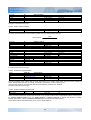
Figures
Figure 1: Relation between basic objects in the Tw Motor .................................................................................................. 7
Figure 2: State diagram of a device .................................................................................................................................. 18
Figure 3: Device Control State Machine............................................................................................................................ 21
Figure 4: Single set point................................................................................................................................................... 23
Figure 5: Change set immediately set point ...................................................................................................................... 24
Figure 6: Interpolation with ip sync every 2 SYNC ............................................................................................................ 26
Figure 7: Interpolation start-up synchronization (ip sync every 3 SYNC) .......................................................................... 26
Figure 8: Homing method 19 and 20................................................................................................................................. 28
Figure 9: Homing method 21 and 22................................................................................................................................. 28
Figure 10: Homing method 26 and 30............................................................................................................................... 29
Figure 11: Control loop performance measurements ........................................................................................................ 34
Figure 12: Leds identification ............................................................................................................................................ 38
Figure 13: Structure of Device Type.................................................................................................................................. 39
Figure 14: Structure of COB-ID Sync Message................................................................................................................. 40
Figure 15: Structure of COB-ID Emergency Message ...................................................................................................... 42
Figure 16: Structure of Revision Number .......................................................................................................................... 43
Figure 17: Structure of RPDO’s COB-ID ........................................................................................................................... 43
Figure 18: Structure of PDO Mapping Entry...................................................................................................................... 44
Figure 19: Structure of TPDO’s COB-ID ........................................................................................................................... 45
Figure 20: Structure of controlword ................................................................................................................................... 47
Figure 21: Speed loop main schema................................................................................................................................. 78
Figure 22: Speed loop output schema .............................................................................................................................. 79
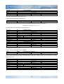
Tables
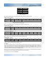
Table 1: Tw Motor CANopen features ................................................................................................................................. 8
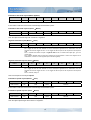
Table 2: Object dictionary layout ......................................................................................................................................... 9
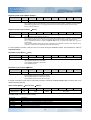
Table 3: Baud rates........................................................................................................................................................... 11
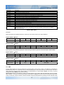
Table 4: Abort codes ......................................................................................................................................................... 14
Table 5: Error register reference ....................................................................................................................................... 16
Table 6: Tw Motor emergency codes reference ................................................................................................................ 17
Table 7: Trigger for state transition ................................................................................................................................... 18
Table 8: NMT states and defined communication objects ................................................................................................. 19
Table 9: Drive states ......................................................................................................................................................... 22
Table 10: State transition .................................................................................................................................................. 22
Table 11: Commands in the controlword........................................................................................................................... 22
Table 12: Device Control related objects .......................................................................................................................... 23
Table 13: Profile position commands ................................................................................................................................ 23
Table 14: Profile position status ........................................................................................................................................ 23
Table 15: Profile Position Mode related objects ................................................................................................................ 24
Table 16: Profile velocity commands................................................................................................................................. 24
Table 17: Profile velocity status......................................................................................................................................... 25
Table 18: Profile Velocity Mode related objects ................................................................................................................ 25
Table 19: Interpolated position commands........................................................................................................................ 26
Table 20: Interpolated position status ............................................................................................................................... 26
Table 21: Interpolated Position Mode related objects ....................................................................................................... 27
Table 22: Homing commands ........................................................................................................................................... 27
Table 23: Homing status ................................................................................................................................................... 27
Table 24: Homing Mode related objects............................................................................................................................ 27
Table 25: Factor group related objects.............................................................................................................................. 30
Table 26: Torque mode commands .................................................................................................................................. 32
Table 27: Torque Mode related objects............................................................................................................................. 32
Table 28: Rotary table commands .................................................................................................................................... 32
Table 29: Rotary table status ............................................................................................................................................ 32
3
Doc. 02655-0-E-M - ENG
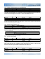
Table 30: Rotary table related objects............................................................................................................................... 33
Table 31: Leds behaviour.................................................................................................................................................. 38
Table 32: Firmware download abort code ......................................................................................................................... 39
Table 33: Controlword operating mode specific bits.......................................................................................................... 47
Table 34: Structure of the statusword ............................................................................................................................... 48
Table 35: Statusword operating mode specific bits ........................................................................................................... 48
Table 36: Default control parameters ................................................................................................................................ 81
4
Doc. 02655-0-E-M - ENG
History
Rev. B
Document modified for the firmware release V1.0.x:
• Notation chapter added (§1.1)
• Asynchronous PDO timing clarification (§2.6)
• Aux input triggered PDO added (§4.6 and object 530Ah.0h)
• Synchronisation Object timing clarification (§2.7)
• SYNC statistics added (§2.7 and objects 5110h.0h, 5111h.0h, 5112h.0h and 530Bh.0h)
• Error codes added and more details for some error codes in the Table 6
• Factor group approximation clarification (§3.7)
• Position error calculation clarification (§4.1)
• Torque mode chapter added (§4.3)
• Speed loop control chapter added (§4.5)
• Digital filters chapter added (§4.7)
• New led behaviour added (§4.8)
• Target position initial value clarification (object 607Ah.0h)
• Home offset enhancement (object 607Ch.0h)
• Hardware configuration object added (5311h.0h)
• User configuration version object added (5312h.0h)
• Objects 5102h.0h, 607Dh, 5380h.0h, 5012h.0h, 5013h.0h added
• Objects added to Velocity control parameters (object 60F9h)
• Adaptation to the new functions of the second application example (§6.2 and §6.3)
• Adaptation to the new functions of speed loop control schema (Appendix A)
• Cockpit configuration tool chapter removed
Rev. C
Document modified for the firmware release V1.1.x:
• LSS Switch modes clarification (§2.4)
• Error code object added (603Fh.0h)
• SYNC PDO overtime error code added in the Table 6
• CAN SW overrun / CAN HW overrun / PDO length error codes now trigger an Abort connection event
• More details on approximation of factor group (§3.7)
• More details on current and speed loops (§4.2 and §4.5)
• More details and wrong equations fixed in the digital filter (§4.7)
• Filtered velocity demand value object 5103h.0h added
• Disable software position limits flag added on object 5380h.0h
• More details on object 1011h
Rev. D
Document modified for the firmware release V1.2.x:
• New behaviour of the SYNC Controller alarm generation (§2.8)
• Enable rotary axis flag added on object 5380h.0h
• Enable signed position flag added on object 5380h.0h
• Homing mode chapter added (§3.6)
• Rotary table control chapter added (§4.4)
• New functionality added to auxiliary digital input (§4.6)
• Bits added to statusword (object 6041h.0h)
• New encoder type added (§4.1)
• COB-ID value range clarification
• Objects 6098h.0h, 6099h, 609Ah.0h, 5320h, 5321h.0h, 5322h.0h, 5323.0h added
5
Doc. 02655-0-E-M - ENG
Rev. E
Document modified for the firmware release V1.3.x:
• Application zero position in homing mode added (§3.6)
• Control loop performance measurements parameters added (§4.5)
• More details on rotary axis enabled bit (§4.1)
• More details on default values for the hardware configuration dependant objects (Appendix C)
• Objects 5120h.0h, 5121h.0h, 5122h.0h, 5123h.0h, 5124h.0h, 5330h.0h added
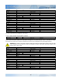
Please read also the changelog.txt file included in the firmware package for more information
6
Doc. 02655-0-E-M - ENG
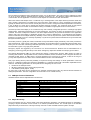
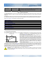
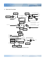
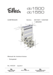
1. Introduction
The Tw drives use a subset of the standard CANopen protocol to provide access to whole drive parameters. Several
standard CANopen functions codes are supported as described in the CiA DS301.
DSP
305
Network
Controller
Can
Motion
Controller
DS
301
Object
Dictionary
Motor/
Encoder
DSP
402
Non-volatile
storage
Tw Motor
Figure 1: Relation between basic objects in the Tw Motor
The field bus that is used here is defined in ISO 11898 (Controller Area Network CAN for high-speed communication).
The Layer-1/2 protocol (Physical Layer/Data Link Layer) that is implemented in all CAN modules provides, amongst other
things, the requirements for data. Data transport or data request is made by means of a data telegram (Data Frame) with
up to 8 bytes of user data, or by a data request telegram (Remote Frame or RTR). Communication Objects (COB) are
labeled by an 11-bit Identifier (ID) that also determines the priority of Objects. A Layer-7 protocol (Application Layer) was
developed, to decouple the application from the communication. The service elements that are provided by the
Application Layer make it possible to implement an application that is spread across the network. These service
elements are described in the CiA DS301.
The Tw drives are slave systems and then they need a CANopen master system (master CANopen, PC with Cockpit
(refer to / 6), PC with CANopen configuration tool, PLC, etc.) to be configured via the CAN bus.
The Tw Motor uses also a subset of the CiA DSP402, which standardizes the objects necessary for the digital motion
controller.
1.1. Notation
In this manual all references from CiA standards are adapted to the specific Tw drives. These does not includes features
not implemented on the Tw drives.
All COBs are expressed in a structured table, including the COB-ID, where the length of the COB depends on how many
bytes (Bx) are represented.
All objects are articulated is in the form index.sub-index, e.g. 1018h.2h means index 1018h sub-index 2h. If only index
is specified then it means reference to the complete RECORD or ARRAY object, refer to §2.2.
All numerical data expressed inside a COB are always reordered starting from the least significant octet, refer to §2.3.
2. CANopen protocol – DS301
The CANopen protocol is one of the most common CAN protocols. Since 1995 the CANopen specification is handed
over to CAN in Automation (CiA) international users and manufacturers group. The European standardization authorities
7
Doc. 02655-0-E-M - ENG
have accepted the CANopen Device Specification version 4.01 as EN 50325-4. The main concept of CANopen is based
on use of an object dictionary (basically device’s variables, parameters, etc.). This dictionary gathers data related to the
communication and the application. To access to these objects two methods are used: SDO & PDO.
SDO mean Service Data Object and is a confirmed way to exchange data of the object dictionary between master and
slave. Usually a slave device is an SDO server, this mean that it could answer to a query originated by an SDO client,
typically the master device of the network. Usually this protocol is used to configure the internal parameters of the device;
in the Tw Motor it is used also to upgrade the firmware wherever necessary. The confirmed nature of this protocol
generate a large amount of traffic on the CAN bus making it unsuitable for high-speed real-time communication.
The PDO (Process Data Object) is an unconfirmed way and extremely configurable protocol to exchange high-speed
real-time data, maximizing advantages of the CAN architecture. The transfer of PDOs is performed with no protocol
overhead. The PDOs correspond to entries in the device Object Dictionary and provide the interface to the application
objects. Data type and mapping of application objects into a PDO is determined by a corresponding PDO mapping
structure within the Device Object Dictionary. Basically a PDO could be asynchronous (means that the transmission is
triggered on a specific event or is remotely requested) or synchronous (means that the transmission is synchronized with
the Synchronization Object).
The SYNC producer, typically the master, broadcasts the Synchronization Object periodically. This SYNC provides the
basic network clock. There can be a time jitter in transmission by the SYNC producer corresponding approximately to the
latency due to some other COB being transmitted just before the SYNC. In order to guarantee timely access to the CAN
bus the SYNC is given a very high priority identifier.
Emergency objects are triggered by the occurrence of a device internal error situation and are transmitted from an
emergency producer (typically the slave) on the device. Emergency objects are suitable for interrupt type error alerts.
The Network Management (NMT) is node oriented and follows a master-slave structure. NMT objects are used for
executing NMT services. Through NMT services, nodes are initialized, started, monitored, reset or stopped. All nodes are
regarded as NMT slaves. An NMT Slave is uniquely identified in the network by its node-ID, a value in the range of
[1..127]. NMT requires that one device in the network fulfils the function of the NMT Master.
LSS (Layer Setting Service) offers the possibility to inquire and change the settings of certain parameters of the local
layers on a CANopen module with LSS Slave capabilities by a CANopen module with LSS Master capabilities via the
CAN bus. The following parameters can be inquired and/or changed by the use of LSS:
• Node-ID of the CANopen Slave
• Bit timing parameters of the physical layer (baud rate)
• LSS address (Identity Object, 1018h)
By using LSS a LSS Slave can be configured for a CANopen network without using any devices like DIP-switches for
setting the parameters. Then the configuration can be stored on a non-volatile memory.
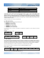
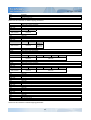
2.1. CANopen Protocol Parameters
Standard features that are implemented in Tw Motor are:
NMT:
Baud rate / node-ID:
Server SDO:
Tx PDO:
Rx PDO:
PDO Mapping:
PDO Modes:
Emergency object:
Sync object:
Time object:
Error control protocols:
Slave only
1000 / 800 / 500 / 250 / 125 / 100 / 50 kbps; node 1 ÷ 127
1
8
8
User programmable (only in pre-operational state)
All types supported
Yes
Yes
No
Boot-up / Node Guarding / Heartbeat
Table 1: Tw Motor CANopen features
2.2. Object Dictionary
The most important part of a device profile is the Object Dictionary description. The Object Dictionary is essentially a
grouping of objects accessible via the network in an ordered pre-defined fashion. The overall layout of the standard
Object Dictionary is shown below. This layout closely conforms to other industrial serial bus system concepts:
8
Doc. 02655-0-E-M - ENG
Index
0000h-0FFFh
1000h-1FFFh
2000h-5FFFh
6000h-9FFFh
A000h-FFFFh
Object
data definition / reserved
communication profile area (DS301)
manufacturer specific area (Tw Motor specific)
standardized device profile area (DSP402)
other profiles / reserved
Table 2: Object dictionary layout
A 16-bit index is used to address all entries within the Object Dictionary. In case of a simple variable (VAR) the index
directly references the value. In case of records (RECORD) and arrays (ARRAY) however, the index addresses the
whole data structure. To allow individual elements of structures of data to be accessed via the network a sub-index is
defined. For single Object Dictionary entries such as an UNSIGNED8, INTEGER32 etc. the value for the sub-index is
always zero. For complex Object Dictionary entries such as arrays or records with multiple data fields the sub-index
references fields within a data-structure pointed to by the main index. The fields accessed by the sub-index can be
composed of different data types.
All objects accessible in the Tw Motor are described in §5.
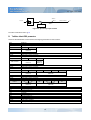
2.3. Data Type Encoding
Basic data types used for accessing the object dictionary are:
• INTEGER8 (8 bit signed integer)
• INTEGER16 (16 bit signed integer)
• INTEGER32 (32 bit signed integer)
• UNSIGNED8 (8 bit unsigned integer)
• UNSIGNED16 (16 bit unsigned integer)
• UNSIGNED32 (32 bit unsigned integer)
For transmission across a CAN bus a bit sequence is reordered into a sequence of octets, starting from the least
significant octet.
Examples:
Unsigned16 value: 18911 = 49DFh
B0
B1
⇒
49DFh
B0
B1
DFh
49h
Unsigned32 value: 98827716 = 05E3 FDC4h
B0
B1
B2
B3
⇒
05E3 FDC4h
B0
B1
B2
B3
C4h
FDh
E3h
05h
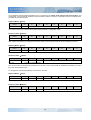
2.4. LSS – DSP305
Since in the LSS Protocol all LSS Slaves use the same COB to send information to the LSS Master, there must be only
one LSS Slave at a time that communicates with the LSS Master. For all protocols the LSS Master takes the initiative, a
LSS Slave is only allowed to transmit within a confirmed service after it has been uniquely switched into configuration
mode. Since there can be almost one confirmed LSS service outstanding at a time, the synchronization is established.
The factory default setting for the Tw Motor is node-ID equal to 1 and baud rate equal to 125kbps.
Master could switch the slave to configuration mode with the switch mode global command:
Request (Master → Slave)
COB-ID
B0
B1
7E5h
04h
01h
B2
B3
B4
B5
Reserved
The Tw Motor support also the switch mode selective (see / 2).
9
B6
B7
Doc. 02655-0-E-M - ENG
A non-standard command that find appliance only on Tw Motor is the switch mode selective with serial number. This
command let a network with all powered-on and connected Tw Motor to switch to configuration mode one selected drive,
providing only his serial number.
Request (Master → Slave)
COB-ID
B0
7E5h
80h
B1
B2
B3
B4
B5
serial number
B6
B7
Reserved
The response came only if desired slave exist and has switched to configuration mode.
Response (Slave → Master)
COB-ID
B0
7E4h
44h
B1
B2
B3
B4
B5
B6
B7
reserved
After a slave has switched to configuration mode the master could modify the node-ID with the following command:
Request (Master → Slave)
COB-ID
B0
B1
7E5h
11h
node-ID
node-ID:
B2
B3
B4
B5
B6
B7
B5
B6
B7
reserved
01h to 7Fh
Response (Slave → Master)
COB-ID
B0
B1
B2
7E4h
11h
error code
spec. error
error code:
B3
B4
reserved
0 means successful executing
This command alter all COB-ID that by default are in the form xxxh+node-ID (COB-ID of PDOs and of EMCY), but only if
they have still the default value.
To configure the baud rate the following command is to be used:
Request (Master → Slave)
COB-ID
B0
B1
B2
7E5h
13h
00h
Speed idx
speed idx:
B3
B4
B5
B6
B7
B6
B7
reserved
see Table 3
Response (Slave → Master)
COB-ID
B0
B1
B2
7E4h
13h
error code
spec. error
error code:
B3
B4
B5
reserved
0 means successful executing
10
Doc. 02655-0-E-M - ENG
Baud Rate
1000 kbps
800 kbps
500 kbps
250 kbps
125 kbps
100 kbps
50 kbps
Speed idx
0
1
2
3
4
5
6
Table 3: Baud rates
Then master can activate the new speed immediately with the following optional command:
Request (Master → Slave)
COB-ID
B0
7E5h
15h
switch delay:
B1
B2
B3
B4
B5
switch delay
B6
B7
reserved
the duration of the two periods of time to wait until the bit timing parameters switch is done (first period)
and before transmitting any COB with the new bit timing parameters after performing the switch (second
period). The time unit of switch delay is 1 ms.
Master now should store the new configuration in the internal non-volatile storage:
Request (Master → Slave)
COB-ID
B0
7E5h
17h
B1
B2
B3
B4
B5
B6
B7
B5
B6
B7
B6
B7
reserved
Response (Slave → Master)
COB-ID
B0
B1
B2
7E4h
17h
error code
spec. error
error code:
B3
B4
reserved
0 means successful executing
Finally, master should switch back the slave to the normal operation mode:
Request (Master → Slave)
COB-ID
B0
B1
7E5h
04h
00h
B2
B3
B4
B5
reserved
For further details and examples please refer to / 2 and §6.1.
2.5. SDO
With Service Data Objects (SDO) the access to entries of a device Object Dictionary is provided. As these entries may
contain data of arbitrary size and data type, SDOs can be used to transfer multiple data sets (each containing an
arbitrary large block of data) from a client to a server (download or write) and vice versa (upload or read). The client can
control via a multiplexor (16 bit index and 8 bit sub-index of the Object Dictionary) which data set is to be transferred. The
contents of the data set are defined within the Object Dictionary.
Basically a SDO is transferred as a sequence of segments. Prior to transferring the segments there is an initialization
phase where client and server prepare themselves for transferring the segments.
This is the sequence of the object download:
11
Doc. 02655-0-E-M - ENG
Initialization download request (Master → Slave)
COB-ID
B0
600h+node-ID
21h
data size:
B1
B2
B3
index
B4
B5
subidx
B6
B7
B6
B7
B6
B7
data size
this is the overall size (in bytes) of the object to be downloaded
If the transfer could be done the server acknowledge the initialization phase:
Initialization download response (Slave → Master)
COB-ID
B0
580h+node-ID
60h
B1
B2
B3
index
B4
B5
subidx
reserved
Then the object download begin with a series of a segments:
Segment download request (Master → Slave)
COB-ID
B0
600h+node-ID
client cmd
client cmd:
B1
B2
B3
B4
B5
segment data
bit 7-5: segment download request, equal to 0
bit 4: toggle bit: this bit must alternate for each subsequent segment that is downloaded. The first
segment will have the toggle bit set to 0. The toggle bit will be equal for the request and the response
COB
bit 3-1: indicates the number of bytes in segment data that do not contain data. Bytes [8-n, 7] do not
contain data
bit 0: indicates whether there are still more segments to be downloaded: 0 means more segment to be
downloaded, 1 means no more segments (this is the last segment)
Segment download response (Slave → Master)
COB-ID
B0
580h+node-ID
server cmd
server cmd:
B1
B2
B3
B4
B5
B6
B7
reserved
bit 7-5: segment download response, equal to 1
bit 4: toggle bit: this bit must alternate for each subsequent segment that is downloaded. The first
segment will have the toggle bit set to 0. The toggle bit will be equal for the request and the response
COB
bit 3-0: reserved, always 0
This is the sequence of the object upload:
Initialization upload request (Master → Slave)
COB-ID
B0
600h+node-ID
40h
B1
B2
index
B3
B4
B5
subidx
B6
B7
B6
B7
reserved
If the transfer could be done the server acknowledge the initialization phase:
Initialization upload response (Slave → Master)
COB-ID
B0
580h+node-ID
41h
Data size:
B1
B2
index
B3
B4
subidx
this is the overall size (in bytes) of the object to be uploaded
Then the object upload begin with a series of a segments:
12
B5
data size
Doc. 02655-0-E-M - ENG
Segment upload request (Master → Slave)
COB-ID
B0
600h+node-ID
client cmd
client cmd:
B1
B2
B3
B4
B5
B6
B7
reserved
bit 7-5: segment upload request, equal to 3
bit 4: toggle bit: this bit must alternate for each subsequent segment that is uploaded. The first segment
will have the toggle bit set to 0. The toggle bit will be equal for the request and the response COB
bit 3-0: reserved, always 0
Segment upload response (Slave → Master)
COB-ID
B0
580h+node-ID
server cmd
server cmd:
B1
B2
B3
B4
B5
B6
B7
segment data
bit 7-5: segment upload response, equal to 0
bit 4: toggle bit: this bit must alternate for each subsequent segment that is uploaded. The first segment
will have the toggle bit set to 0. The toggle bit will be equal for the request and the response COB
bit 3-1: indicates the number of bytes in segment data that do not contain data. Bytes [8-n, 7] do not
contain data
bit 0: indicates whether there are still more segments to be uploaded: 0 means more segment to be
uploaded, 1 means no more segments (this is the last segment)
It is also possible to transfer a data set of up to four bytes during the initialization phase. This mechanism is called an
expedited transfer:
Expedited request (Master → Slave)
COB-ID
B0
600h+node-ID
client cmd
client cmd:
B1
B2
index
B3
B4
subidx
B5
B6
B7
data (optional)
2Fh: expedited download of 8 bit data
2Bh: expedited download of 16 bit data
23h: expedited download of 32 bit data
40h: expedited upload
Expedited response (Slave → Master)
COB-ID
B0
580h+node-ID
server cmd
server cmd:
B1
B2
index
B3
B4
subidx
B5
B6
B7
data (optional)
60h: expedited download successful
4Fh: expedited upload of 8 bit data successful
4Bh: expedited upload of 16 bit data successful
43h: expedited upload of 32 bit data successful
If transfer would fail for some reason, both master and slave could send the abort transfer COB (it could be sent in any
download/upload segment):
Abort transfer (Master → Slave or Slave → Master)
COB-ID
B0
600h+node-ID or
580h+node-ID
80h
B1
B2
index
B3
subidx
The abort code could be one of the following:
Abort code
0503 0000h
0504 0000h
0504 0001h
0504 0005h
0601 0001h
0601 0002h
Description
SDO toggle bit not alternated during segmented transfer.
SDO protocol timed out.
SDO client/server command specifier not valid or unknown.
Out of dynamic allocated memory.
Attempt to read a write only object.
Attempt to write a read only object.
13
B4
B5
B6
abort code
B7
Doc. 02655-0-E-M - ENG
Abort code
0602 0000h
0604 0041h
0604 0042h
0604 0047h
0606 0000h
0607 0010h
0607 0012h
0607 0013h
0609 0011h
0609 0030h
0609 0031h
0609 0032h
0609 0036h
0800 0020h
0800 0021h
0800 0022h
Description
Object does not exist in the object dictionary.
Object cannot be mapped to the PDO.
The number and length of the objects to be mapped would exceed PDO length.
SDO wrong COB length
Access failed due to an hardware error of the internal non-volatile storage
Data type does not match, length of service parameter does not match
Data type does not match, length of service parameter too high
Data type does not match, length of service parameter too low
Sub-index does not exist.
Value range of parameter exceeded (only for write access).
Value of parameter written too high.
Value of parameter written too low.
Maximum value is less than minimum value.
Data cannot be saved or restored from the internal non-volatile storage, wrong signature.
Data cannot be saved or restored from the internal non-volatile storage because the power output is enabled
Data cannot be transferred or stored to the application because of the present device state, depending on the
object accessed either NMT state is operational or power output enabled, see description of the Write
override attribute in §5.
Table 4: Abort codes
Examples:
Master download (via expedited transfer) to a slave the 16 bit value 1AC7h to the object 6066h.0h:
Request (Master → Slave)
COB-ID
B0
600h+node-ID
2Bh
B1
B2
B3
6066h
B4
00h
B5
B6
1AC7h
B7
0
Response (Slave → Master)
COB-ID
B0
580h+node-ID
60h
B1
B2
B3
6066h
B4
B5
00h
B6
B7
0
Master upload (via expedited transfer) from a slave the object 1018h.4h (that is a 32 bit value equal to 0098 9CABh):
Request (Master → Slave)
COB-ID
B0
600h+node-ID
40h
B1
B2
B3
1018h
B4
B5
04h
B6
B7
B6
B7
0
Response (Slave → Master)
COB-ID
B0
580h+node-ID
43h
B1
B2
B3
1018h
04h
B4
B5
0098 9CABh
For further details please refer to / 1.
2.6. PDO
Process Data Objects are used to transmit any process data for the process control. The PDOs are transmitted in
broadcast and without any confirmation back to the transmitting device. There are two kinds of use for PDOs. The first is
data transmission and the second data reception. It is distinguished in Transmit-PDOs (TPDOs, from slave to master)
and Receive-PDOs (RPDOs, from master to slave).
Synchronous PDOs are transmitted on SYNC event and could be cyclic (means that the transmission is every n SYNC,
with n between 1 and 240), acyclic (means that the transmission is triggered on event and then synchronized with SYNC
event) or RTR-Only (only for TPDOs, means that master request the transmission by sending an RTR COB with same
14
Doc. 02655-0-E-M - ENG
COB-ID of the specific TPDO). The received RPDOs data is internally processed on the SYNC event, not immediately
after receiving RPDO itself. The transmitted TPDOs data is sampled on the SYNC event, not at the time of transmission.
TPDOs are dispatched immediately after the SYNC event, while RPDOs normally are dispatched from the master after
all TPDOs and just before next SYNC event.
Asynchronous TPDOs could be triggered on event (means on changing data) or RTR-Only (means that master request
the transmission by sending an RTR COB with same COB-ID of the specific TPDO). It is not guaranteed that the time on
which data change and the time the TPDO are transmitted are the same. The received data of the asynchronous RPDOs
are internally dispatched as soon as possible.
TPDOs could also have enabled the RTR allowed attribute, this means that, disregarding the transmission type, the
master has the possibility to force the transmission by RTR COB.
Examples:
Predefined RPDO #3, with control word (16 bit) and target position (32 bit):
COB-ID
B0
400h+node-ID
B1
B2
B3
6040h.0h
B4
B5
607Ah.0h
Predefined TPDO #2, with status word (16 bit) and mode of operation display (8 bit):
COB-ID
280h+node-ID
B0
B1
6041h.0h
B2
6061h.0h
In the Tw Motor it is possible to change the COB-ID (independently from the node-ID), the data mapping (for all PDOs)
and specify an inhibit time (valid only for asynchronous TPDOs), that defines the minimum time that has to elapse
between two consecutive invocations of a transmission service for that TPDO. In addition the Tw Motor provide an aux
input triggered TPDO, refer to §4.6.
For all PDOs configuration there are specific entries in the object dictionary: 1400h and 1600h for RPDOs, 1800h and
1A00h for TPDOs. Refer to §6.2 for examples on how to fully configure PDOs.
For further details please refer to / 1.
2.7. SYNC
The Synchronization Object does not carry any data and is unconfirmed service.
Sync COB (broadcast)
COB-ID
080h
This object trigger the internal parameters exchange to and from all synchronous PDO buffers.
Tw Motor also use the SYNC object to synchronize his internal machine cycle with that of the Synchronization Object
producer, but only if the SYNC cycle time is multiple of 250µs; also the time tolerance should be below ±5µs; the
maximum recommended cycle time is 25ms. In addition it is suggested that the master start generating the SYNC object
at least 100ms before Start remote node command and/or before enabling output power, to let drive synchronization.
This feature (enabled by default) could be disabled if the user experience troubles with tolerance greater than specified.
The Tw Motor also monitor continuously the time period of the SYNC object, giving the user the ability to have a
feedback on the quality of the SYNC object; this is given in the form of three parameters, the minimum cycle time, the
maximum cycle time and the average cycle time. Those parameters are updated every user-specified amount of time
(default 2 seconds), giving back the cycle time quality of the past period and letting the user never miss any intermittently
discontinuity of the SYNC (e.g. missing transmission of SYNC objects). The statistics are not cumulative, at the end of
every update time period the drive reset the internal counters. Please note that in the Tw Motor all the EMCY, NMT and
SDO objects are not internally synchronized with the SYNC object, then they could be dispatched at any time.
The SYNC related objects are: 1005h.0h, 60C2h, 60C3h, 5110h.0h, 5111h.0h, 5112h.0h, 530Bh.0h and 5380h.0h bit 2.
15
Doc. 02655-0-E-M - ENG
For further details please refer to / 1.
2.8. EMCY
Tw Motor support the emergency object, both for hardware and software faults. An emergency object is transmitted only
once per 'error event'.
Emergency COB (broadcast)
COB-ID
B0
B1
B2
B3
B4
B5
error
Tw Motor error register
register
standard CiA error code (object 603Fh.0h)
standard CiA error register (object 1001h.0h)
mapped in the manufacturer status register (object 1002h.0h)
080h+node-ID
error code
error code:
error register:
Tw Motor error reg.:
B6
B7
reserved
Every bit in the error register refer to a category of faults, more than one bit at time could be set to 1, meaning that more
than one fault is active. Bit 0 is set to 1 if one or more faults are active, is reset to 0 if all faults are cleared.
Every bit in the Tw Motor error register refer to a specific faults of the motion controller and the OS but the
communication module; more than one bit at time could be set to 1, meaning that more than one fault is active.
Bit
0
1
2
3
4
5
7
Meaning
generic error
current
voltage
temperature
communication error (overrun, error state)
device profile specific
manufacturer specific
Table 5: Error register reference
After the fault is cleared the slave transmit and EMCY object with error code equal to 0h, meaning that one fault is
cleared. The other fields report remaining active faults; if none, all fields will be 0h.
Except when specified, the behaviour of non-fatal faults are described in the Fault Reaction option code (object
605Eh.0h).
Error
code
Tw Motor
error register
bit
0
Fatal
fault
Description
Remedy / Cause
2110h
Error
register
bit
1
Yes
3210h
2
1
Yes
Overcurrent / power short-circuit /
power module fail
DC-link overvoltage
4210h
4310h
6100h
7121h
3
3
N/A
7
2
3
4
5
No
No
Yes
Yes
Device overtemperature
Power section overtemperature
Internal software
Motor blocked / following error
overlimit
7300h
7
6
Yes
Encoder
8700h
4
7
No
6320h
N/A
8
-
Overcurrent; if the fault is persistent please
contact technical service
Check the functionality of the external clamp
device, refer to / 4
Environment too warm, refer to / 4
Heavy working cycle, refer to / 4
Contact technical service
Check that output shaft is free of rotating /
check the VS PID parameters, refer to
object 60F9h / check that the difference
between two set-point in Interpolated mode is
coherent with maximum admitted speed, refer
to §3.5 / check the motor blocked threshold,
refer to object 5305h.0h
Position encoder disalignment; if the fault is
persistent please contact technical service
The timing of the SYNC object is not accurate,
refer to §2.7. It is generated only when bit 2 of
the object 5380h.0h is enabled.
Check data consistency of written object
6060h.0h
‡
Sync controller
Parameter error on object 6060h.0h
16
Doc. 02655-0-E-M - ENG
Error
code
6321h
Error
register
bit
N/A
Tw Motor
error register
bit
9
Fatal
fault
Description
Remedy / Cause
-
Parameter error on object 6086h.0h
Check data consistency of written object
6086h.0h
The voltage on the auxiliary input has switched
off or is detached
Check overall external DC-link capacitor, refer
to / 4
Heavy working cycle, refer to / 4
The time slot assigned to the sinchronous
PDOs is not enough to process all user defined
PDOs, reduce the number of PDO or the
number of objects inside them
Sent only if the object 6007h.0h state a specific
action, none by default
The non volatile parameters memory is
corrupted, the drive has booted with default
configuration; issue a store parameters
command (object 1010h); if the fault Is
persistent please contact technical service
The shaft has reached the maximum tolerated
mechanical speed, ~3500 rpm
Reduce network load for the slave
The node has received a new instance of one
RPDO before processing the old one, refer to
§2.6
Noisy network environment or incorrect bus
termination, refer to / 4
Extremely noisy network environment
*
9001h
7
10
No
3211h
2
11
Yes
4211h
6200h
3
N/A
12
13
No
Yes
Motor overtemperature
SYNC PDO processing overtime
8A01h
N/A
16
No
Abort connection
5530h
N/A
17
-
Flash parameters error
8401h
N/A
18
Yes
Overspeed
8110h
8111h
4
4
N/A
N/A
No
‡
No
8120h
4
N/A
8140h
4
8130h
†
Loss of external auxiliary input
voltage
DC-link rising too fast
‡
CAN HW overrun
CAN SW overrun
No
‡
N/A
No
‡
4
N/A
No
‡
CAN controller entered error
passive mode
Recover from CAN controller busoff
Life guard error
8220h
4
N/A
No
‡
8230h
4
N/A
-
PDO out of memory
8231h
4
N/A
-
Aux input triggered PDO parameter
error
PDO length error
Master has not polled the node within the life
time, refer to §2.9
The length of RPDO does not match with the
internally calculated length, refer to §2.6
Due to internal handling of PDOs, reduce the
number of PDO or the number of objects inside
them or the order of these objects; all PDOs are
not created, thus unavailable
The transmission type of this PDO is invalid,
refer to §4.6; all PDOs are not created, thus
unavailable
Table 6: Tw Motor emergency codes reference
The error register is mapped to the object 1001h.0h and the Tw Motor error register is mapped to the object 1002h.0h,
while the last error code is mapped in the object 603Fh.0h. For further information on faults behaviour refer to §3.2.
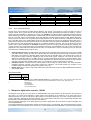
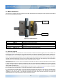
2.9. NMT
The Network Management (NMT) divides in two categories, as follow.
2.9.1.
Module Control Services
Through Module Control Services, the NMT master controls the state of the NMT slaves. The state attribute is one of the
values {STOPPED, PRE-OPERATIONAL, OPERATIONAL, INITIALISING}. The Module Control Services can be
performed with a certain node or with all nodes simultaneously.
*
This emergency code trigger an Auxiliary Input event, which the behaviour is defined by the object 5300h.0h
This event trigger a special fault reaction: the three power output lines are shorted together, acting both as brake for the motor and as a brake resistor to
reduce DC-link voltage
‡
This emergency code trigger an Abort Connection event, which the behaviour is defined by the object 6007h.0h
†
17
Doc. 02655-0-E-M - ENG
NMT COB
COB-ID
B0
B1
000h
CS
node-ID
CS:
Node-ID:
01h: start remote node
02h: stop remote node
80h: enter pre-operational remote node
81h: reset remote node
82h: reset communication of remote node
Node-ID of the remote node or 00h for broadcast to all nodes
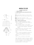
Immediately after power-on the node enter in the PRE-OPERATIONAL state; then master could follow these steps to
set-up the nodes before enabling them to the OPERATIONAL state:
• Configuration of all device parameters, including communication parameters (via Default SDO)
• start transmission of SYNC, wait for synchronization of all devices
• Start of Node Guarding
All of those operations are optional as Tw Motor support full parameters saving to internal non-volatile storage and the
requirement of SYNC depend from the specific application.
The state transition (except the PRE-OPERATIONAL to OPERATIONAL transition) could trigger an Abort Connection
event, which the behaviour is defined by the object 6007h.0h. State transitions are caused by reception of an NMT COB
used for module control services or an hardware reset.
Power on or hardware reset
1
Initialization
2
11
Pre-operational
7
10
5
3
4
Stopped
6
8
9
Operational
Figure 2: State diagram of a device
1
2
3,6
4,7
5,8
9,10,11
At Power on the initialization state is entered autonomously
Initialization finished - enter pre-operational automatically
Start remote node
Enter pre-operational remote node
Stop remote node
Reset remote node / Reset communication of remote node
Table 7: Trigger for state transition
18
Doc. 02655-0-E-M - ENG
INITIALISING
PDO
SDO
SYNC
EMCY
Boot-Up Object
Network Management Objects
PRE-OPERATIONAL
STOPPED
X
X
X
OPERATIONAL
X
X
X
X
X
X
X
X
Table 8: NMT states and defined communication objects
2.9.2.
Error Control Protocols
Through Error control services the NMT detects failures in the network. Local faults in a node may lead to a reset or
change of state. Error Control services are achieved principally through periodically transmitting of COBs by a device.
There exist two possibilities to perform Error Control. The guarding is achieved through transmitting guarding requests
(Node guarding protocol) by the NMT Master. If a NMT Slave has not responded within a defined span of time (node life
time) or if the NMT Slave’s communication status has changed, the NMT Master informs its NMT Master Application
about that event. The slave uses the guard time and lifetime factor from its Object Dictionary to determine the node life
time. If the NMT Slave is not guarded within its life time, the NMT Slave informs its local Application about that event. If
guard time and life time factor are 0 (default values), the NMT Slave does not guard the NMT Master. Guarding starts for
the slave when the first remote-transmit-request for its guarding identifier is received. This may be during the boot-up
phase or later. A slave establishes the heartbeat mechanism for a device through cyclically transmitting a message. One
or more devices in the network are aware of this heartbeat message. If the heartbeat cycle fails for the slave the local
application on the master will be informed about that event. It is not allowed for a slave to use both protocol; in case both
are activated the heartbeat protocol will be used.
•
•
•
Node Guarding Protocol: The NMT Master polls (with an RTR COB with same COB-ID of the Error Control COB)
each NMT Slave at regular time intervals. This time-interval is called the guard time and may be different for each
NMT Slave. The response of the NMT Slave contains the state of that NMT Slave. The node life time is given by
the guard time (object 100Ch.0h) multiplied by the life time factor (object 100Dh.0h). The node life time can be
different for each NMT Slave. If the NMT Slave has not been polled during its life time, it issues an EMCY object
with error code 8130h (see §2.8) and then the action indicated in the Abort Connection (object 6007h.0h) is issued.
The error is cleared either restarting polling slave or by a reset node / reset communication command.
Heartbeat Protocol: It defines an Error Control Service without need for remote frames. The slave transmits a
Heartbeat message cyclically. The master receives the indication. The master guards the reception of the
Heartbeat within the Producer Heartbeat Time (object 1017h.0h).
Bootup Protocol: It is used to signal that a NMT slave has entered the node state PRE-OPERATIONAL after the
state INITIALISING.
Error Control COB
COB-ID
700h+node-ID
t:
s:
B0
7
t
6..0
s
used only with the Node Guarding Protocol, it toggle between 0 and 1 every time the COB is sent (the
first time after boot-up or reset node / reset communication command is 0); other ways is 0
00h: Bootup
04h: Stopped
05h: Operational
7Fh: Pre-Operational
3. CANopen for digital motion controller – DSP402
The purpose of this profile is to give drives an understandable and unique behavior on the CAN bus. The purpose of
drive units is to connect axle controllers or other motion control products to the CAN bus. At run time, data can be
obtained from the drive unit via CAN bus by either polling or event driven (interrupt). The motion control products have a
process data object mapping for real time operation. This communication channel is used to interchange real-time data
like set-points or present values like a position actual value e.g.
The two principal advantages of the profile approach for device specification are in the areas of system integration and
device standardization.
If two independent device manufacturers design products that have to communicate, then both manufacturers must be
provided with a device specification from the other one. These specifications will widely differ in formal and terminological
19
Doc. 02655-0-E-M - ENG
aspects from one company to another. The concept of device profiling provides a standard for producing such
specifications. By adopting this approach, all manufacturers will specify their devices in a similar fashion, what greatly
reduces the effort involved in system integration.
The other obvious advantage of the profile approach for device specification is, that it can be used to guide
manufacturers into producing standardized devices. The advantages of standardized devices are numerous. Perhaps
most important is the idea, that a standardized device decouples a system integrator from a specific supplier. If one
supplier cannot meet special application demands, a system designer can use devices from another supplier with
reduced effort. On the other hand the device manufacturers are not forced any more to implement private protocols for
each customer.
A device profile defines a ‘standard’ device. This standard device represents really basic functionality, every device
within this device class must support. This mandatory functionality is necessary to ensure, that at least simple nonmanufacturer-specific operation of a device is possible. For example the standard drive unit provides a Quick stop
function to stop a drive. This function is defined as mandatory, such that any drive unit supporting the CANopen Device
Profile for Drives and Motion Control, can be halted using the same message.
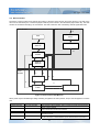
3.1. Architecture of the drive
The basic architecture is composed of two main modules:
• Device Control: the state machine executes the starting and stopping of the drive and several mode specific
commands.
• Modes of Operation: The operation mode defines the behavior of the drive. The following modes are defined in
this profile:
1. Profile position mode: The positioning of the drive is defined in this mode. Speed, position and
acceleration can be limited and profiled moves using a Trajectory Generator are possible as well.
2. Profile velocity mode: The Profile Velocity Mode is used to control the velocity of the drive with no
special regard of the position. It supplies Trajectory Generation.
3. Interpolated position mode: This mode allow the time interpolation of single axes and the spatial
interpolation of coordinated axes.
4. Torque mode: The user could drive the motor feeding torque reference (current reference); please
note that this is not the same as the standard Profile torque mode, but Tw Motor specific.
5. Homing mode: This is the method by which a drive seeks the home position (also called, the datum,
reference point or zero point).
6. Rotary table control: The user could select a position on a rotary table by an index (up to 126
positions); the drive will select the best route choosing the rotation direction.
The Tw Motor support switching between the various modes of operation, also when the axes is moving.
20
Doc. 02655-0-E-M - ENG
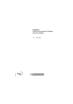
3.2. Device Control
The device control function block controls all functions of the drive (drive function and power section). The state of the
drive can be controlled by the controlword (object 6040h.0h) and is shown in the statusword (object 6041h.0h). The state
machine is controlled externally by the controlword. The state machine is also controlled by internal signals like faults.
Power Disabled
Fault
13
Fault Reaction
Active
Start
0
14
Not ready to
Switch On
Fault
1
15
Switch On
Disabled
2
7
Ready to
Switch On
Power
Enabled
3
6
Switched On
9
8
4
10
5
12
11
Operation
Enable
Quick Stop Active
16
Figure 3: Device Control State Machine
When power output is enabled high voltage switching is applied to the motor phases, torque could be applied or could be
null.
State
Not Ready to Switch
On
Switch On Disabled
Statusword
xxxx xxxx x0xx 0000
xxxx xxxx x1xx 0000
Ready To Switch On
Switched On
xxxx xxxx x01x 0001
xxxx xxxx x01x 0011
Operation Enable
xxxx xxxx x01x 0111
Description
The Tw Motor is being initialized, then is not ready to accept command and the
power output is disabled
Tw Motor initialization is complete, then is ready to accept command, the power
output and the drive functions are disabled
The drive functions are disabled, the drive is ready to enable power output
The drive functions are disabled, the drive has power output enabled, the motor
shaft has no torque
The drive functions and power output are enabled, the torque could be applied
on the motor shaft, no faults detected, specific selected Mode Of Operation is
21
Doc. 02655-0-E-M - ENG
State
Statusword
Description
executed
Quick Stop Active
xxxx xxxx x00x 0111
The drive functions and power output are enabled, the quick stop function is
being executed or finished and the motor stopped (depending from object
605Ah.0h)
Fault Reaction Active
xxxx xxxx x0xx 1111
The drive functions and power output are enabled, the fault recovering is being
executed (defined by the object 605Eh.0h and if not a fatal fault, see Table 6)
Fault
xxxx xxxx x0xx 1000
A fault is occurred in the device, the drive functions and power output are
disabled
For complete reference look at statusword (object 6041h.0h)
Table 9: Drive states
Transition
0
1
2
3
4
5
Event
Reset
Tw Motor has finished self-initialization
Shutdown command
Switch On command
Enable Operation command
Disable Operation command
6
7
8
Shutdown command
Quick Stop or Disable Voltage command
Shutdown command
9
Disable Voltage command
10
Disable Voltage or Quick Stop command
11
12
13
Quick Stop command
Quick Stop function executed or Disable
Voltage command
A fault is occurred
14
The fault reaction is completed
15
Fault Reset command
16
Enable Operation command
Action
Tw Motor internal self-initialization
Activate communication
None
Enable power output
The drive functions are enabled and torque could be applied
The drive functions are disabled, the behaviour of the motor
depend from the object 605Ch.0h
Disable power output
None
The drive functions and power output are disabled, the behaviour
of the motor depend from the object 605Bh.0h
The drive functions and power output are disabled, the motor is
free to rotate
The drive functions and power output are disabled, the motor is
free to rotate
The quick stop function is executed, (see object 605Ah.0h)
The drive functions and power output are disabled, the motor is
free to rotate
Execute the appropriate fault reaction (see object 605Eh.0h) if
non-fatal fault, see Table 6
The drive functions and power output are disabled, the motor is
free to rotate
Reset of the fault condition; after leaving the state Fault, the bit
Fault Reset in the command word has to be cleared by the host
The drive functions are enabled; the transition is possible
according to the object 605Ah.0h
Table 10: State transition
Command
Controlword
Shutdown
xxxx xxxx xxxx x110
Switch On
xxxx xxxx xxxx x111
Disable Voltage
xxxx xxxx xxxx xx0x
Quick Stop
xxxx xxxx xxxx x01x
Disable Operation
xxxx xxxx xxxx 0111
Enable Operation
xxxx xxxx xxxx 1111
Fault Reset
xxxx xxxx 1xxx xxxx
For complete reference look at controlword (object 6040h.0h)
Transitions
2,6,8
3
7,9,10,12
7,10,11
5
4,16
15
Table 11: Commands in the controlword
The drive functions depend from the selected mode of operation (object 6060h.0h), that could be checked reading the
mode of operation display (object 6061h.0h); this selection also modifies the behaviour of some bits of the controlword
and the statusword. The specific drive function is executed only when the drive status is Operation Enabled.
Refer to §6.2 and to §6.3 for examples on how to use the controlword.
6040h.0h: Controlword
6041h.0h: Statusword
605Bh.0h: Shutdown option code
605Ch.0h: Disable operation option code
605Ah.0h: Quick stop option code
605Eh.0h: Fault reaction option code
22
Doc. 02655-0-E-M - ENG
6060h.0h: Modes of operation
6061h.0h: Modes of operation display
6085h.0h: Quick stop deceleration
Table 12: Device Control related objects
3.3. Profile Position Mode
A target position (object 607Ah.0h) is applied to the trajectory generator; it generates a position demand value (object
6062h.0h) that is feed as reference position to the internal speed loop. These two function blocks are controlled by
individual parameter set.
The trajectory generator support only linear ramp (trapezoidal profile), with separate parameters for acceleration (object
6083h.0h) and deceleration (object 6084h.0h), velocity profile (object 6081h.0h) and optional non-zero end velocity (the
speed the motor has on reaching target position, object 6082h.0h). All those parameters could also be changed during
positioning: the trajectory generator will always follows the new rules; for example, if you change velocity profile
parameter, the drive will reach the new speed using the profile acceleration or deceleration.
This mode is driven by specific bits of the controlword and the statusword, as follow:
Command
New Set Point
Change Set Immediately
Controlword
xxxx xxxx xxx1 xxxx
xxxx xxxx xx1x xxxx
Abs / rel
xxxx xxxx x1xx xxxx
Halt
xxxx xxx1 xxxx xxxx
Description
Assume new target position
If 0 the new positioning is started after finish of the current positioning, if
1 the new positioning interrupt the current positioning
If 0 the target position is an absolute value, if 1 is a relative value
(incremental)
Stop the motor with the profile deceleration (depend from the object
605Dh.0h); on reset resume the interrupted positioning
For complete reference look at controlword (object 6040h.0h)
Table 13: Profile position commands
State
Target Reached
Statusword
xxxx x1xx xxxx xxxx
Description
The target position is reached (see object 6067h.0h and object 6068h.0h) or, if
an halt command is issued, the velocity of the motor is zero
Set Point Acknowledge xxx1 xxxx xxxx xxxx
Trajectory generator has assumed the new target position
Following Error
xx1x xxxx xxxx xxxx
Following error, the thresholds are defined in the objects 6065h.0h and
6066h.0h
For complete reference look at statusword (object 6041h.0h)
Table 14: Profile position status
First of all the target position have to be loaded with the desired value, then the New Set Point bit has to be set; the
drive signal the acquisition (and then the execution of the movement) of the target position setting the Set Point
Acknowledge bit. Resetting the New Set Point also reset the Set Point Acknowledge, this operation does not affect
the current positioning. Now a new target position could be loaded and signaled via New Set Point to the drive: if the
previous targeting is not completed the drive will keep Set Point Acknowledge low until target is reached (signaled in
the statusword), then it go high and the drive start the new positioning. If Change Set Immediately is set together with
the New Set Point, then the new positioning is started immediately, still respecting the trajectory generator parameters.
New Set Point
Set Point Ack
Speed
t1
Figure 4: Single set point
23
t2
Doc. 02655-0-E-M - ENG
New Set Point
Set Point Ack
Speed
t1
t2
Figure 5: Change set immediately set point
If Abs / rel is set together with New Set Point then the target position is treated as an signed increment of the present
target position.
Symmetrically around the target position a window (object 6067h.0h) is defined for the accepted position range, that is
target position±position window. If a drive is situated (object 6064h.0h) in the accepted position range over the time
position window time (object 6068h.0h) the Target Reached bit is set.
A following error window (object 6065h.0h) is defined for the accepted following error tolerance. If the modulus of the
following error actual value (object 60F4h.0h) is greater than the following error window for more than following error time
out time (object 6066h.0h) then the Following Error bit is set.
Refer to §6.2 and to §6.3 for examples on profile position mode.
6040h.0h: Controlword
6041h.0h: Statusword
605Dh.0h: Halt option code
607Ah.0h: Target position
607Dh: Software position limit
6081h.0h: Profile velocity
6082h.0h: End velocity
6083h.0h: Profile acceleration
6084h.0h: Profile deceleration
6086h.0h: Motion profile type
6062h.0h: Position demand value
6064h.0h: Position actual value
6065h.0h: Following error window
6066h.0h: Following error time out
6067h.0h: Position window
6068h.0h: Position window time
60F4h.0h: Following error actual value
Table 15: Profile Position Mode related objects
3.4. Profile Velocity Mode
A target velocity (object 60FFh.0h) is applied to the trajectory generator; it generates a velocity demand value (object
606Bh.0h) that is feed as reference speed to the internal speed loop. These two function blocks are controlled by
individual parameter set.
The trajectory generator support only linear ramp (trapezoidal profile), with separate parameters for acceleration (object
6083h.0h) and deceleration (object 6084h.0h).
This mode is driven by specific bits of the controlword and the statusword, as follow:
Command
Halt
Controlword
xxxx xxx1 xxxx xxxx
Description
Stop the motor with the profile deceleration (depend from the object
605Dh.0h)
For complete reference look at controlword (object 6040h.0h)
Table 16: Profile velocity commands
24
Doc. 02655-0-E-M - ENG
State
Target Reached
Statusword
xxxx x1xx xxxx xxxx
Description
The target velocity is reached (see object 606Dh.0h and object 606Eh.0h) or, if
an halt command is issued, the velocity of the motor is zero
Speed
xxx1 xxxx xxxx xxxx
The speed is equal to zero (see object 606Fh.0h and object 6070h.0h)
For complete reference look at statusword (object 6041h.0h)
Table 17: Profile velocity status
The Target Reached bit is set when the modulus difference between the velocity demand value and the velocity actual
value (object 606Ch.0h) is within the velocity window (object 606Dh.0h) longer than the velocity window time (object
606Eh.0h).
The Speed bit is reset as soon as the velocity actual value exceeds the velocity threshold (object 606Fh.0h) longer than
the velocity threshold time (object 6070h.0h). Below this threshold the bit is set and indicates that the axle is stationary.
Refer to §6.2 and to §6.3 for examples on profile velocity mode.
6040h.0h: Controlword
6041h.0h: Statusword
605Dh.0h: Halt option code
6083h.0h: Profile acceleration
6084h.0h: Profile deceleration
6069h.0h: Velocity sensor actual value
606Bh.0h: Velocity demand value
606Ch.0h: Velocity actual value
606Dh.0h: Velocity window
606Eh.0h: Velocity window time
606Fh.0h: Velocity threshold
6070h.0h: Velocity threshold time
60FFh.0h: Target velocity
Table 18: Profile Velocity Mode related objects
3.5. Interpolated position Mode
The interpolated position mode is used to control multiple coordinated axes or a single axle with the need for timeinterpolation of set-point data. The interpolated position mode uses
x
computed points
the SYNC (see §2.7) as the time synchronization mechanism for a
time coordination of the related drive units.
The interpolation data record contains the interpolation data; the Tw
Motor supports only synchronous operation and linear interpolation,
P2
thus the data record has only one field, the position set-point (object
60C1h); the interpolation time period (object 60C2h) is referred to the
ip sync period. The ip sync is the event that triggers the execution of
the set-point data, the SYNC is the physically COB on the network
P1
and trigger the sync PDO; the relation between two is called sync
definition (object 60C3h): it specifies how many SYNC should be
t
received to trigger one ip sync.
t1
t2
To ensure proper operations, the interpolation data should be supplied
continuously in real time via PDO (see §2.6), one set-point per ip sync for the calculation of the next demand value. For
each interpolation cycle, the drive will calculate a position demand value (at every internal cycle time that is 250µs) by
interpolating positions over a period of time. The position demand value is feed directly as input of the speed loop,
bypassing the trajectory generator and thus neglecting all velocity and acceleration limitations.
Optionally the set-points could be iterated across a 2nd order digital filter (see §4.7).
WARNING: when the Enable rotary axis flag (object 5380h.0h) is enabled, the position set-point (object
60C1h) must always falls between the boundary. User has to take care about wrapping this object. For further
information refer to §4.1.
25
Doc. 02655-0-E-M - ENG
set-point
P1
P2
P3
SYNC
ip sync
P1
position
P2
interpolation time period
Figure 6: Interpolation with ip sync every 2 SYNC
This mode is driven by specific bits of the controlword and the statusword, as follow:
Command
Enable ip mode
Halt
Controlword
xxxx xxxx xxx1 xxxx
xxxx xxx1 xxxx xxxx
Description
Enable movement of the axes
Stop the motor with the profile deceleration (depend from the object
605Dh.0h)
For complete reference look at controlword (object 6040h.0h)
Table 19: Interpolated position commands
State
Target Reached
Statusword
xxxx x1xx xxxx xxxx
Description
The target position is reached or, if an halt command is issued, the velocity of
the motor is zero
Ip mode active
xxx1 xxxx xxxx xxxx
Axes movement active
For complete reference look at statusword (object 6041h.0h)
Table 20: Interpolated position status
To have an accurate start-up condition, it is suggested to map the controlword (object 6040h.0h) in one sync PDO and
then use it to give the drive the Enable ip mode; in this way only the following SYNC will start triggering the ip sync,
apart when drive has began receiving the SYNC.
set
Enable ip mode
SYNC
ip sync
Figure 7: Interpolation start-up synchronization (ip sync every 3 SYNC)
6040h.0h: Controlword
6041h.0h: Statusword
605Dh.0h: Halt option code
607Dh: Software position limit
60C1h: Interpolation data record
60C2h: Interpolation time period
60C3h: Interpolation sync definition
6062h.0h: Position demand value
6064h.0h: Position actual value
26
Doc. 02655-0-E-M - ENG
60F4h.0h: Following error actual value
5309h: Position set-point filter constants
Table 21: Interpolated Position Mode related objects
3.6. Homing Mode
This is the method by which a drive seeks the home position (also called, the datum, reference point or zero point).
There are various methods of achieving this, all of them use a home switch (zero point switch) in mid-travel. The home
switch have to be connected to the auxiliary digital input (see §4.6), no additional configuration for this input has to be
done. The user could specify an homing speed, an homing acceleration and an homing method, that will be used
throughout all the procedure. At the end of the seeking, the drive will set-up the home offset (object 607Ch.0h) with the
right value to zero all the position objects on the home position; the previous value of the home offset is ignored. If the
needing is for a value other than zero, preset the desired position value in the application zero position (object 5330h.0h).
The successfully completed procedure will be signalled by the Homing done bit in the statusword (object 6041h.0h).
In order to start seeking of home position, the Home operation start bit has to be set. If the selected method is not
supported, the Homing error bit will be activated; otherwise the Homing attained bit activation will signal the
successfully end of homing procedure and the zero speed of the motor. Now Home operation start bit could be reset.
WARNING: if Enable rotary axis flag (bit 8 of the object 5380h.0h) is set, at the end of the homing procedure
wait until the Rotary axis enabled bit in the statusword (object 6041h.0h) is set before using position objects,
as the drive could need some time to update his internal status (see §4.1).
This mode is driven by specific bits of the controlword and the statusword, as follow:
Command
Homing operation start
Controlword
xxxx xxxx xxx1 xxxx
Halt
xxxx xxx1 xxxx xxxx
Description
The transition 0→1 start the homing, the transition 1→0 interrupt the
homing
Stop the motor with the profile deceleration (depend from the object
605Dh.0h); the homing procedure will restart from the beginning
For complete reference look at controlword (object 6040h.0h)
Table 22: Homing commands
State
Homing attained
Homing error
Statusword
xxx1 xxxx xxxx xxxx
xx1x xxxx xxxx xxxx
Description
Homing mode carried out successfully, motor is stopped
The selected method is not supported. This flag is activated when Homing
operation start bit is activated
Homing done
1xxx xxxx xxxx xxxx
The homing is done, this bit remain active up to a node reset or a power-off
For complete reference look at statusword (object 6041h.0h)
Table 23: Homing status
6040h.0h: Controlword
6041h.0h: Statusword
605Dh.0h: Halt option code
607Ch.0h: Home offset
6098h.0h: Homing method
6099h: Homing speeds
609Ah.0h: Homing acceleration
6064h.0h: Position actual value
5330h.0h: Application Zero Position
Table 24: Homing Mode related objects
27
Doc. 02655-0-E-M - ENG
3.6.1.
Homing methods 19 and 20
The initial direction of the movement is dependent on the state of the home switch. The home position is on the point
where the home switch changes its state. The point at which the reversal direction of movement takes place is anywhere
after the change of state of the home switch.
The seeking ends on high to low home switch transition and counterclockwise movement direction (19) or on low to high
home switch transition and clockwise movement direction (20).
CCW
CW
19
19
20
20
Home switch state
Figure 8: Homing method 19 and 20
3.6.2.
Homing methods 21 and 22
The initial direction of the movement is dependent on the state of the home switch. The home position is on the point
where the home switch changes its state. The point at which the reversal direction of movement takes place is anywhere
after the change of state of the home switch.
The seeking ends on high to low home switch transition and clockwise movement direction (21) or on low to high home
switch transition and counterclockwise movement direction (22).
CCW
CW
21
21
22
22
Home switch state
Figure 9: Homing method 21 and 22
3.6.3.
Homing methods 26 and 30
These methods detect the transition high to low of the home switch as home position; if the home switch is low on
starting, the drive ignore it and wait for the transition. The direction of the movement is clockwise (26) or
counterclockwise (30).
28
Doc. 02655-0-E-M - ENG
CCW
CW
30
26
Home switch state
Figure 10: Homing method 26 and 30
3.7. Factor group
There is a need to interchange physical dimensions and sizes into the internal device units. To implement the
interchange, several factors are necessary. The factors defined in the factor group set up a relationship between internal
device units (from here d.u.) and physical units (p.u.). The factors are result of the calculation of two parameters called
dimension index and notation index. These factors are directly used to normalize the physical values. Another
parameters that take part in the factors calculation are the gear ratio (object 6091h) and the feed constant (object
6092h), that defines the ratio between the output shaft and the motor shaft, in case of gearbox between those two. See
§5 to see which position, velocity and acceleration objects are affected by factor group.
The default setting of the Tw Motor is to use d.u.; those are the mathematical relations between d.u. and radians at motor
output shaft (and reverse equations):
1
⋅ θ [rad ]
2π
65536 2 1
ω [d .u.] =
⋅
⋅ ω[rad ]
s
4000 2π
2
65536
1
ω& [d .u.] =
⋅
⋅ ω& [rad 2 ]
s
4000 2 2π
1
⋅ θ [d .u.]
65536
4000
ω [rad s ] = 2π ⋅
⋅ ω [d .u.]
65536 2
4000 2
ω& [rad 2 ] = 2π ⋅
⋅ ω& [d .u.]
s
65536 2
θ [d .u.] = 65536 ⋅
θ [rad ] = 2π ⋅
where θ , ω and ω& are respectively angular position, speed and acceleration. All computations are made using d.u.,
those three are all expressed as signed 32 bit integer value. Refer to §4.1 on how those relations are computed.
When user choose a p.u. set to express those values, the conversion between user defined units and d.u. is made at the
communication interface level, this mean that internally all values are still stored and computed using d.u.; also, due to
the unavoidable approximation, the value read from an object could slightly differ from the value written. Still the number
format is signed 32 bit integer. If it is essential for user application the signed position value, refer to Enable signed
position flag (§4.1).
The conversion of the units is made through a time-optimized algorithm, yielding it suitable both for SDO (§2.5) and PDO
(§2.6). The conversion factor is computed using 32 bit floating point constants and variables, giving the computation in
the form y = k ⋅ x ; then k is converted in a mantissa/exponent form k = m ⋅ 2 e , where 1 < m ≤ 0.5 ; this value is
converted to a 24 bit constant; all those computations are done offline. In the real-time computation the 32 bit input value
is integer multiplied by the 24 bit constant, yielding an 48 bit result value (the least significant 8 bit are truncated); this
value is shifted by e (left or right, depending from the sign) and then 32 bit output value is taken. This kind of conversion
-23
could yield an approximation that should be evaluated regarding the application, but expected to be in the range of ±2
multiplied the value and rounded to the lower integer that is greater than or equal the resulting value (e.g., the
approximation of the value 134200000 expressed in p.u. is calculated as: 134200000×2-23=15.998, then the real value is
134200000±16 p.u.).
The k computation includes encoder resolution, gear ratio, feed constant, the selected p.u. and the magnitude.
The supported p.u. are both linear and rotational unit; the unit could be specified separately for position, speed and
acceleration, but all three must be in the same group: linear, rotational or d.u. The p.u. are specified with two parameters
for each of position, speed and acceleration: dimension index and notation index; the first define the kind of p.u. (e.g.
n
radians, meters, revolutions per minute, etc.); the second define the desired magnitude in term of 10 (e.g. if meters p.u.
-3
0
3
is chosen, then mm is 10 , m is 10 , km is 10 , etc.).
29
Doc. 02655-0-E-M - ENG
The relation between position internal units and user selected position p.u. is:
θ [d .u.] =
position encoder resolution ⋅ gear ratio
⋅ θ [ p.u.]
feed constant
where position encoder resolution (object 608Fh) is a constant ratio (equal to 65536); in this case the relation could be
simplified in:
θ [ p.u.] feed constant
=
θ [rad ] 2π ⋅ gear ratio
where p.u. is referred to the desired output shaft and rad to the motor shaft radians rotational unit. Note that for the
position p.u. the k is not related with the selected position dimension index (object 608Ah.0h) and the position notation
index (object 6089h.0h). The purpose of these two is to establish the ratios between position p.u., velocity p.u. and
acceleration p.u. These are computed internally depending on the respective dimension index (objects 608Ch.0h and
608Eh.0h) and notation index (objects 608Bh.0h and 608Dh.0h) selected.
The feed constant and gear ratio are defined as ratio of two 32 bit integer number; we suggest to use large number to
define both ratios, this practice could reduce the overall approximation error.
Refer to §6.4 for examples on how to use the factor group.
6089h.0h: Position notation index
608Ah.0h: Position dimension index
608Bh.0h: Velocity notation index
608Ch.0h: Velocity dimension index
608Dh.0h: Acceleration notation index
608Eh.0h: Acceleration dimension index
608Fh: Position encoder resolution
6090h: Velocity encoder resolution
6091h: Gear ratio
6092h: Feed constant
Table 25: Factor group related objects
4. Tw Motor specific functions
Features described here are Tw Motor proprietary.
4.1. Position encoder
The Tw Motor is equipped with an absolute single-turn encoder, an absolute multi-turn encoder or a two-poles
resolver (overall accuracy apart, this is this is functionally the same of the absolute single-turn encoder, so in the chapter
is always referred as absolute single-turn); the term absolute refer to the capability of the encoder to give at power-up
and without any initialization the right angular position. User has the capability to get information via software on which
equipment is installed from the hardware configuration object (5311h.0h).
The absolute single-turn encoder has the capability to give the angular position over one turn, expressed as a 16 bit
number; the drives equipped with this encoder simulate via software the multi-turn capability, giving the user the
possibility to feed angular position up to 65536 turns; this means that the d.u. for the angular position is expressed as:
the MSB 16 bit give the number of turns, the LSB 16 bit give the angular position in one turn, giving the relations shown
in the §3.7. At each power-up the MSB 16 bit of the position actual value (object 6064h.0h) will be initialized to 0 or -1.
The absolute multi-turn encoder add to the absolute single turn encoder the capability of distinguish up to 4096 turns
at power-up; in this case the drive do not simulate any multi-turn capability and then the user can feed angular position
up to 4096 turns. If the user download angular position above this limit, the drive ignores the MSB 4 bit of the given
position. By default, uploading position objects from the drive will give those bits at zero, always resulting as unsigned
value between 0 and 268435455 (0FFF FFFFh). Enabling the Enable signed position flag (bit 9 of the object 5380h.0h)
let the user to upload these values as signed: this is done by sign-extending the bit 27 of the position object: now the
possible position values are between -134217728 (F800 0000h) and +134217727 (07FF FFFFh). E.g., if the real position
is 041A 0031h the bit 27 is zero and then the uploaded value is the same; if the real position is 0D1A 0031h the bit 27 is
30
Doc. 02655-0-E-M - ENG
one and then the uploaded value is FD1A 0031h. This flag works in the same way also with the Factor group (§3.7). Note
that the only position objects that are affected by this flag are those that in the object dictionary reference report exactly
position Factor Group as unit of measure.
In both cases, when position reach upper or lower boundary the drive automatically wrap the position to the opposite
boundary.
The position error is calculated as 32 bit difference from the reference and feedback positions (28 bit in case of the multiturn encoder); then drive choose fastest direction to reach the target position: e.g., suppose that the present position is
65500 turns (single-turn encoder) and the user feed a target position equal to 30 turns, then the drive will advance the
motor from 65500 to 65535, wrap to 0 and finally reach the 30 turns target position, reaching final position in 66 positive
turns; the 32 bit difference of those two numbers is: 001E 0000h-FFDC 0000h=0042 0000h. The same example fits for
the multi-turn encoder, the drive will make the difference of the positions as they would be 28 bit numbers: x01E 0000hxFDC 0000h=0042 0000h.
The speed is calculated as difference between two consecutive reading of the position encoder (250µs) and then shifting
into the MSB 16 bit, to improve the quality of the speed loop. The acceleration is simply computed as difference of the
speed, still every 250µs.
4.1.1.
Rotary axis mode
Enabling the Enable rotary axis flag (bit 8 of the object 5380h.0h) let the user to deal with an arbitrary sized rotary axis.
This mode affects all the position objects and works in all mode of operations. When the actual position rises above the
Table dimension / Rotary axle dimension (object 5321h.0h) the value is automatically wrapped to zero and viceversa.
E.g., this mode is useful when using a rotating table with a gearbox ratio not power of 2.
Please also note that:
•
When rotary axis is enabled, drive loose his absolute encoder feature: the position become a virtual position and
an homing cycle (either manual or automatic) is required to find the zero point at power up
•
The drive use the position actual value (object 6064h.0h) to check if wrapping has to be done or not; when this
object reach the boundary it is possible that other position objects (e.g. the position demand value) falls outside the
boundary. This is a normal behaviour, as the drive have to recognize which direction has to be taken to reach the
desired reference position; this also means that user could send a target position outside the boundary, the drive
will cover all travel as default manner (except interpolated position mode, §3.5)
WARNING: changing this bit will have effect on the drive only after a node reset or power off – power on cycle.
In order to enable (or disable) set (or reset) the bit in the object 5380h.0h, then issue a store parameters
command (object 1010h) and finally issue a NMT node reset command (§2.9).
WARNING: immediately after power on or after changing the objects 5321h.0h or 607Ch.0h (this could also
done automatically by the Homing procedure), wait until the Rotary axis enabled bit in the statusword (object
6041h.0h) is set before using position objects, as the drive could need some time to update his internal status.
4.2. Current loops
The Tw Motor current loops are tuned in factory on the specific motor coupled to the drive, so they normally does not
need to be accessed from the users. Anyway, in some applications could be useful to set-up a torque limit: the torque is
directly related to the current, the torque limit could be customized by the output speed loop current limit parameter
(object 60F9h.6h).
The d.u. (internal device units) for all current related parameters are:
I [ Arms ] =
6.02
⋅ I [d .u.]
32768
I [d .u.] =
32768
⋅ I [ Arms ]
6.02
The current loops are updated at 8 khz.
4.3. Torque Mode
A target torque (current reference) is fed to the input of the current loop (object 5000h.0h); it generates instantaneously
desired torque on the motor shaft.
31
Doc. 02655-0-E-M - ENG
This mode support the Halt command, as follow:
Command
Halt
Controlword
xxxx xxx1 xxxx xxxx
Description
Stop the motor with the profile deceleration (depend from the object
605Dh.0h)
For complete reference look at controlword (object 6040h.0h)
Table 26: Torque mode commands
No additional statusword bits are used in this mode.
6040h.0h: Controlword
6041h.0h: Statusword
605Dh.0h: Halt option code
6084h.0h: Profile deceleration
5000h.0h: Current quadrature reference
5001h.0h: Current direct reference
5010h.0h: Current quadrature feedback
5011h.0h: Current direct feedback
Table 27: Torque Mode related objects
4.4. Rotary table control
The user could select a position on a rotary table by an index (up to 126 positions). The positions are indexed by a target
index (object 5323h.0h), user has to download all the absolute positions in the table positions array (object 5320h). It is
possible to specify a gear play compensation (object 5322h.0h) to achieve a better accuracy on the positioning; the
compensation is done only when the direction of rotation is counterclockwise by subtracting from the target position the
desired over-travel.
Three possibilities exist for the rotary table positioning:
•
Absolute with best-route selection: the drive compute the shortest route to reach the target, by choosing clockwise
or counterclockwise rotation
•
Absolute positioning: the sign of the target index determines the rotation direction
•
Relative positioning: the signed target index is added to actual target (and wrapped, if necessary), the sign
determines the rotation direction
WARNING: In order to use this profile the Rotary axis mode (§4.1) must be enabled.
This mode is driven by specific bits of the controlword and the statusword, as follow:
Command
Absolute best-route
Absolute positioning
Relative positioning
Halt
Controlword
xxxx xxxx x001 xxxx
xxxx xxxx x011 xxxx
xxxx xxxx x1x1 xxxx
xxxx xxx1 xxxx xxxx
Description
Absolute positioning with best-route
Absolute positioning without best-route
Relative positioning
Stop the motor with the profile deceleration (depend from the object
605Dh.0h); on reset resume the interrupted positioning
For complete reference look at controlword (object 6040h.0h)
Table 28: Rotary table commands
State
Warning
Target Reached
Statusword
xxxx xxxx 1xxx xxxx
xxxx x1xx xxxx xxxx
Description
Something prevent the positioning, see in the following text
The target position is reached (see object 6067h.0h and object 6068h.0h) or, if
an halt command is issued, the velocity of the motor is zero
Set Point Acknowledge xxx1 xxxx xxxx xxxx
Trajectory generator has assumed the new target index
For complete reference look at statusword (object 6041h.0h)
Table 29: Rotary table status
Issuing the command immediately start the positioning, this is signalled by the Set Point Acknowledge bit that remain
active until user reset the command bits in the controlword. Once started, the positioning could be cancelled only using
either halt or quick stop or device controls commands. If the Warning bit is issued in place of the Set Point
Acknowledge then some of the following reason prevent the positioning:
32
Doc. 02655-0-E-M - ENG
•
•
•
Rotary axis mode (§4.1) is not enabled
The table positions array is either empty or has some entries outside the table dimension or NV storage is
corrupted
The absolute target index is zero or above the number of entries in the table positions array
Symmetrically around the target position a window (object 6067h.0h) is defined for the accepted position range, that is
target position±position window. If a drive is situated (object 6064h.0h) in the accepted position range over the time
position window time (object 6068h.0h) the Target Reached bit is set.
6040h.0h: Controlword
6041h.0h: Statusword
605Dh.0h: Halt option code
6081h.0h: Profile velocity
6083h.0h: Profile acceleration
6084h.0h: Profile deceleration
6067h.0h: Position window
6068h.0h: Position window time
5320h: Table positions array
5321h.0h: Table dimension / Rotary axis dimension
5322h.0h: Gear play compensation
5323h.0h: Rotary table target index
5380h.0h: Global option flags
Table 30: Rotary table related objects
4.5. Speed loop control
In the Tw drives the speed loop control act both as closed loop position control and closed loop speed control; in the first
case the position demand generated by the trajectory generator or by the interpolator is fed to the input of the closed
loop; in the second case the speed demand is integrated, thus generating a position demand to be fed to the input of the
closed loop.
Then the position demand is optionally limited, in order to keep the absolute value of the position error below an user
specified value; this function, jointly with the output speed loop current limit, allow the shaft to run at different speed than
the demanded value when an external torque greater than the limit is applied, without saturating the closed loop.
After that the position demand value is filtered, then differentiate two times to obtain the speed reference value and the
acceleration reference value.
The encoder position value is optionally sign-inverted and/or offset, giving the user the ability to choose which rotating
direction the shaft should move giving incrementing position (or positive velocity) and to select the preferred zero
position. The user could choose which appliance comes first, sign-inversion or offset.
Then the resulting value is differentiate two times to obtain the speed feedback value and the acceleration feedback
value.
Now all the reference and feedback values goes into the closed loop regulator, which is combined with different gains;
one is for the position error, one for each speed and one for each acceleration. By default the gain for the speed value is
the same for the reference and the feedback (in favour of the compatibility with the old applications), resulting in a gain
for the speed error. With the acceleration reference gain the user could reduce the following error during acceleration
and deceleration stages.
Then the sum is fed into a limited integrator block and the output is added to the previous sum, giving the output value of
the closed loop regulator. Now this value is optionally filtered, magnitude (of power of 2) scaled and limited, then it is fed
as input of the current closed loop regulator.
Optionally the user could enable the field weakening function, that decreases the loss of torque at higher speed (refer to
the object 5380h.0h bit 3).
The speed loop control is updated at 4 khz.
For further information refer to Appendix A and to §4.1.
4.5.1.
Performance measurements
In order to have some feedback from the drive about the speed loop control performance, five parameters are provided,
as follow.
33
Doc. 02655-0-E-M - ENG
The following error at maximum speed (object 5120h.0h) is measured at the beginning of the deceleration ramp: this
value is useful in those applications in which the position error during movement is crucial, like flying cutting machine. For
ordinary positioning this value could be ignored.
In order to get faster positioning, e.g. reducing the time the drive enter and stay in the position window, three
measurements are employed. The overshoot at the end of the deceleration ramp (object 5123h.0h) give a measure of
the position error at the time in which the motor theoretically should be in the target position; reducing this error is a good
starting point to reduce the positioning time. The position window entering time (object 5122h.0h) tell how much time is
spent from the end of the deceleration ramp until the position error remain stable inside the position window, thus setting
the target reached bit. The maximum overshoot from the end of the deceleration ramp (object 5121h.0h) is the maximum
value reached from the position error entering in the position window: higher gain on the control loop could shift the
system to the instability, giving high values on this measurement and rising positioning time; on the opposite end, lower
gain give a very stable but slow system, giving low values on this measurement and again rising positioning time.
The average windings current (object 5124h.0h) tells if the long time machine cycle could lead in a overtemperature of
the system: this value should stay below the datasheet continuative current. This measurement is done with a long time
constant, thus giving reliable values after long time running (e.g. 1 hour).
Target Reached
Speed Profile
5123h.0h
5120h.0h
5121h.0h, 5122h.0h
Figure 11: Control loop performance measurements
4.6. Auxiliary digital input
This 24V digital input has three different and standalone functions, that could also be used together.
The first is to provide an external and CAN-independent emergency action, that could be an immediate power disable or
a quick stop and power disable functions. By default this option is disabled, that means ignore the input. If enabled, the
emergency action is activated on 24V power loss: so, on behalf of normal operation the 24V on the input must be
applied. This function is controlled by object 5300h.0h. For further information refer to §3.2.
The second function could be used to sample some internal parameters on rising or falling of the digital input with
accuracy up to 125µs, e.g. to get the position actual value when an external switch is activated. In order to enable this
feature, one TPDO has to be chosen (e.g. #5), then filled-up with one or more parameters to be sampled. The
communication parameters have to be as in the table:
PDO
COB-ID
Type
Inhibit time
TPDO #5
4000 0xxxh
1 (synchronous cyclic) or 254 (asynchronous on event)
0
Write in the object 530Ah.0h the number of TPDO chosen (in our example the value 5) and the configuration is done.
When the drive detect state transition (rising or falling, depending on object 5380h.0h bit 5) on the digital input, it sample
the parameters, then dispatch the TPDO on the next SYNC (if transmission type chosen is 1) or immediately (if
transmission type chosen is 254). For further information refer to §2.6.
The third function is to connect the home switch to be used in homing mode. For further information refer to §3.6.
4.7. Digital filters
User has the opportunity to setup a programmable 2nd order digital IIR filter on the position demand value (object
6062h.0h), on the speed loop output value and on the position set-point value (object 60C1h.1h); the filter constants are
respectively on the objects 5307h, 5308h and 5309h. All those filters are based on the same principle and they are
independent from each other. These filters could be used to remove a mechanical resonating frequency, allowing
improve the quality of the speed loop; they could be used as jerk-limiting, especially in the interpolated profile mode,
giving the ability to increase the interpolation time without weakening the output profile; they could be used to reduce the
noise on the output shaft when driven from a master encoder. As counterpart beware of the time-delay introduced by
34
Doc. 02655-0-E-M - ENG
some filters, e.g. the low pass: if it is applied on the position demand value it could yield a bigger following error when
speed is different than zero, especially in the acceleration/deceleration stage.
The generic 2nd order filter, in the Z domain, letting U ( z) the input signal and Y ( z) the filtered signal, is expressed as:
Y (z) =
m0 + m1z −1 + m2 z −2
U(z)
n0 + n1z −1 + n2 z −2
that becomes, in the discrete time domain:
1
[m0u(k ) + m1u(k − 1) + m2u(k − 2) − n1y (k − 1) − n2 y (k − 2)]
y (k ) =
n0
where u (k ) , u(k − 1) and u(k − 2) are respectively the input value at present time, at previous cycle and 2 cycle back,
and where y ( k ) , y (k − 1) and y (k − 2) are respectively the output value at present time, at previous cycle and 2 cycle
nj
m
back; for convenient calculation we assume ai = i and b j = −
, thus yielding:
n0
n0
y (k ) = a0u( k ) + a1u(k − 1) + a2u(k − 2) + b1y (k − 1) + b2 y (k − 2)
The drive executes only fixed point number calculation, so those constants have to be adjusted to the internal
representation by multiplying each constant per 213 (equal to 8192); then those value have to be submitted by
one-complement’s at 16 bit, bringing in each constant in the range ( -4.0 ; +4.0 ). Take care that the algebraic sum of all
constants have to be equal to 8192.
35
Doc. 02655-0-E-M - ENG
The notch filter transfer function in the continuous time domain is expressed as:
F (s ) =
s 2 + ω02
s + ζs + ω02
2
[
where ω 0 rad
s
] is the resonance frequency and ζ
is
the damping factor (greater the damping factor,
greater the damped band width); making the
discretization with the bilinear transformation the
constants to be submitted are:
The blue diagrams are referred to the continuos time domain.
The green diagrams are referred to the discrete time domain
Notch at ω0 = 3770 rad/s, ζ = 0.05
a0 =
4 + TS2ω02
4 + 2ζTS + TS2ω02
a1 =
2TS2ω02 − 8
4 + 2ζTS + TS2ω02
a2 =
4 + TS2ω02
4 + 2ζTS + TS2ω02
b1 = −
2TS2ω02 − 8
4 + 2ζTS + TS2ω02
b2 = −
4 − 2ζTS + TS2ω02
4 + 2ζTS + TS2ω02
The biquad filter transfer function in the continuous time domain is expressed as:
F (s ) =
ωp2 s 2 + 2ξ zωzs + ωz2
⋅
ωz2 s 2 + 2ξ pωps + ωp2
[
where ω z rad
]
[
]
and ω p rad
are respectively the
s
s
resonance frequency and the anti-resonating
frequency, also ξ p and ξ z are the damping factors;
making the discretization with the bilinear
transformation the constants to be submitted are:
a0 =
a1 =
a2 =
The blue diagrams are referred to the continuos time domain.
The green diagrams are referred to the discrete time domain
Biquad at ω z = 3770 rad/s, ω p = 3581 rad/s, ξ z = 0.05, ξ p = 0.2
36
4ωp2 + 4ξ zωzωp2TS + TS2ωz2ωp2
4ωz2 + 4ξ pωz2ωpTS + TS2ωz2ω p2
2TS2ωz2ωp2 − 8ωp2
4ωz2 + 4ξ pωz2ω pTS + TS2ωz2ωp2
4ωp2 − 4ξ zωzωp2TS + TS2ωz2ωp2
4ωz2 + 4ξ pωz2ωpTS + TS2ωz2ω p2
b1 = −
b2 = −
2TS2ωz2ωp2 − 8ωz2
4ω + 4ξ pωz2ωpTS + TS2ωz2ω p2
2
z
4ωz2 − 4ξ pωz2ωpTS + TS2ωz2ωp2
4ωz2 + 4ξ pωz2ωpTS + TS2ωz2ωp2
Doc. 02655-0-E-M - ENG
The low pass filter transfer function in the continuous time domain is expressed as:
F (s ) =
ω02
s + 2ξω0s + ω02
2
[
where ω0 rad
]
is the cut-off frequency and ξ is the
s
damping factor; making the discretization with the
bilinear transformation the constants to be submitted
are:
The blue diagrams are referred to the continuos time domain.
The green diagrams are referred to the discrete time domain
Low pass at ω0 = 1885 rad/s, ξ = 0.6
a0 =
TS2ω02
4 + 4ξω0TS + TS2ω02
a1 =
2TS2ω02
4 + 4ξω0TS + TS2ω02
a2 =
TS2ω02
4 + 4ξω0TS + TS2ω02
b1 = −
2TS2ω02 − 8
4 + 4ξω0TS + TS2ω02
b2 = −
4 − 4ξω0TS + TS2ω02
4 + 4ξω0TS + TS2ω02
In the above filters TS is the sample time period, that is related on how many times per second the filter is iterated; it is
associated to the object the filter applies, refer to the respective filter constants objects.
As example, we calculate a low pass filter with ω0 = 1885 rad/s (300 Hz) and ζ = 0.6; with TS = 250µs it yields the
following constants:
a0 = 0.04148 ⇒ 340 (0154h)
a1 = 0.08297 ⇒ 680 (02A8h)
a2 = 0.04148 ⇒ 340 (0154h)
b1 = 1.41151 ⇒ 11563 (2D2Bh)
b2 = −0.57745 ⇒ −4731 (ED85h)
For further information refer to Appendix A, to §3.5 and to §4.5.
37
Doc. 02655-0-E-M - ENG
4.8. Motor Led Behaviour
The Tw Motor is equipped with two couples of leds, which indicate the motor status (leds on the upper and lower side of
the motor give redundant information).
Led1
Led2
Figure 12: Leds identification
Led1
Led2
Blinking
Off
On
Blinking
Blinking alternately
Blinking simultaneously
Off
On (one side)
Two fast blink
Off (both side)
Motor Status
Power supply Ok. Power output disabled
Power supply Ok. Power output enabled
Fault condition
Waiting for firmware download (due to Firmware download activation or wrong firmware
CRC check)
Low DC link circuit voltage, refer to / 4
Flash memory corrupted, contact technical service
Table 31: Leds behaviour
4.9. Firmware upgrade
At regular intervals on the Phase Motion Control web site is released a firmware upgrade, that could includes new
functions and generic enhancements. The firmware download could be done completely via SDO (master CANopen, PC
with Cockpit (/ 6), PC with CANopen configuration tool, PLC, etc.) and without disconnecting the drive from the network.
Due to the internal hardware limitation, after the upgrade all stored parameters will be lost, but the baud rate and the
node-ID. The flash programming is done on the fly during download: this means that after beginning of the download the
operation have to be successfully completed in order to get again the drive working.
The firmware upgrade has to be done in two steps: the first enable the drive to receive the firmware, the second is the
real transfer of it.
In order to enable the drive to receive the firmware the user has to download the string PmcS (or the 32 bit number 5363
6D50h) in the object 5EF0h.0h. After about 100ms the driver will enter in the firmware download wait status, signaled by
all leds blinking simultaneously.
Now the user has to download the complete .SRE file in the object 1F50h.1h. When download is successfully completed,
the drive wills bootup and after about 1.5 seconds it will send the bootup message (see §2.9).
If a communication error (SDO abort) occurs during firmware download it is necessary to start again the download of the
.SRE file; in this case the drive will remain in the firmware download wait status. If the download is successfully
completed but the drive remain in the firmware download wait status means that the drive does not support the
downloaded firmware; in this case please contact the technical service.
38
Doc. 02655-0-E-M - ENG
Abort code
0503 0000h
0504 0000h
0504 0001h
0601 0000h
0602 0000h
0604 0043h
0606 0000h
Description
SDO toggle bit not alternated during segmented transfer.
SDO protocol timed out.
SDO client/server command specifier not valid or unknown.
Unsupported SDO access.
Object does not exist in the object dictionary.
Corrupted .SRE file.
Access failed due to a hardware error of the internal flash.
Table 32: Firmware download abort code
5. Object Dictionary Reference
The complete Tw Motor object dictionary objects are listed here. For each object there is a set of attributes, as follow:
Object
Object Code
Data Type
Access
Write override
Unit
Default value
PDO mappable
NV storage
This is the object index and sub-index, and the name of the parameter
Kind of the object: var is single value, array is multiple value with same basic data type, record is multiple
value where data fields could be any data type combination
Could be integer8 (signed 8 bit), integer16 (signed 16 bit), integer32 (signed 32 bit), unsigned8,
unsigned16, unsigned32, visible_string (ASCII string without termination)
Read-only (ro), write-only (wo) or read-write (rw); could be limited to read-only depending on the state of
the drive, see the Write override attribute below.
Some objects cannot be written when the NMT state machine is in operational state (operational, see §2.9)
and/or the output power is enabled (power enabled, see §3.2).
Measure unit of the object or if affected by the factor group (position, velocity and acceleration, see §3.7)
The value the object has with the factory settings
Specify if the object could be mapped in a PDO
If yes the object will be permanently stored in non-volatile memory when the user issues the command on
object 1010h
5.1. Communication objects
Those are all implemented objects from the application layer and communication profile CiA DS301 V4.02; for further
information on those objects refer to / 1.
5.1.1.
1000h.0h: Device Type
Object:
Object Code:
Access:
Unit:
PDO mappable:
1000h.0h
var
ro
n/a
no
Device Type
Data Type:
Write override:
Default value:
NV storage:
unsigned32
n/a
0002 0192h
n/a
Describes the type of device and its functionality. It is composed of a 16-bit (LSB) field, which describes the device profile
that is used, and a second 16-bit (MSB) field, which gives additional information about optional functionality of the device.
In this case the device profile is 402 (0192h) and the additional information indicate that is a servo drive (0002h).
MSB
Additional information (16 bit)
LSB
Device profile type (16 bit)
Figure 13: Structure of Device Type
5.1.2.
1001h.0h: Error register
Object:
Object Code:
Access:
Unit:
PDO mappable:
1001h.0h
var
ro
n/a
yes
Error register
Data Type:
Write override:
Default value:
NV storage:
This object is an error register for the drive. It is a part of the EMCY object (§2.8).
39
unsigned8
n/a
n/a
n/a
Doc. 02655-0-E-M - ENG
5.1.3.
1002h.0h: Manufacturer Status Register
Object:
Object Code:
Access:
Unit:
PDO mappable:
1002h.0h
var
ro
n/a
yes
Manufacturer Status Register
Data Type:
Write override:
Default value:
NV storage:
unsigned32
n/a
n/a
n/a
This is the common status register specific for the manufacturer. It is a part of the EMCY object (§2.8).
5.1.4.
1005h.0h: COB-ID Sync Message
Object:
Object Code:
Access:
Unit:
PDO mappable:
1005h.0h
var
rw
n/a
no
COB-ID Sync Message
Data Type:
Write override:
Default value:
NV storage:
unsigned32
operational
0000 0080h
yes
Defines the COB-ID of the Synchronization Object (§2.7). Bits 0-10 define the COB-ID, bits 11-31 should be leaved 0.
MSB
Unused (21 bit), should be 0
LSB
COB-ID (11 bit)
Figure 14: Structure of COB-ID Sync Message
5.1.5.
1008h.0h: Manufacturer Device Name
Object:
Object Code:
Access:
Unit:
PDO mappable:
1008h.0h
var
ro
n/a
no
Manufacturer Device Name
Data Type:
Write override:
Default value:
NV storage:
visible_string
n/a
n/a
n/a
Contain the device code of the Tw Motor.
5.1.6.
100Ah.0h: Manufacturer Software Version
Object:
Object Code:
Access:
Unit:
PDO mappable:
100Ah.0h
var
ro
n/a
no
Manufacturer Software Version
Data Type:
Write override:
Default value:
NV storage:
visible_string
n/a
n/a
n/a
Contain the software release number and the release date.
5.1.7.
100Ch.0h: Guard Time
Object:
Object Code:
Access:
Unit:
PDO mappable:
100Ch.0h
var
rw
ms
no
Guard Time
Data Type:
Write override:
Default value:
NV storage:
unsigned16
operational
0
yes
The objects at index 100Ch and 100Dh include the guard time in milliseconds and the life time factor. The life time factor
multiplied with the guard time gives the life time for the Node Guarding Protocol (§2.9). If 0 then it is disabled.
5.1.8.
100Dh.0h: Life Time Factor
Object:
Object Code:
Access:
Unit:
PDO mappable:
100Dh.0h
var
rw
n/a
no
Life Time Factor
Data Type:
Write override:
Default value:
NV storage:
unsigned8
operational
0
yes
The life time factor multiplied with the guard time gives the life time for the Node Guarding Protocol (§2.9). If 0 then it is
disabled.
40
Doc. 02655-0-E-M - ENG
5.1.9.
1010h: Store Parameters
Object:
Object Code:
1010h
array
Store Parameters
Data Type:
unsigned32
This object let the drive to save all parameters in non-volatile memory. By read access the device provides information
about its saving capabilities.
Sub-index:
Data type:
Access:
Unit:
PDO mappable:
0h
unsigned8
ro
n/a
no
Large sub-index supported
Write override:
Default value:
NV storage:
n/a
no
no
The large sub-index supported for this object, in this case 1.
Sub-index:
Data type:
Access:
Unit:
PDO mappable:
1h
unsigned32
rw
n/a
no
Store all
Write override:
Default value:
NV storage:
operational, power enabled
no
no
This command let the drive store all parameters that have the attribute NV storage. In order to avoid storage of
parameters by mistake, storage is only executed when a specific signature is written to the appropriate sub-Index. The
signature is the string save (or the 32 bit number 6576 6173h). On read the drive provides information about its storage
functionality, in this case storage is executed only on command, not autonomously.
It is possible to store a configuration version in the object 5312h.0h.
5.1.10. 1011h: Restore Default Parameters
Object:
Object Code:
1011h
array
Restore Default Parameters
Data Type:
unsigned32
With this object the default values of parameters according to the communication or device profile are restored.
Sub-index:
Data type:
Access:
Unit:
PDO mappable:
0h
unsigned8
ro
n/a
no
Large sub-index supported
Write override:
Default value:
NV storage:
n/a
no
no
The large sub-index supported for this object, in this case 1.
Sub-index:
Data type:
Access:
Unit:
PDO mappable:
1h
unsigned32
rw
n/a
no
Restore all defaults
Write override:
Default value:
NV storage:
operational, power enabled
no
no
This command let the drive restore all parameters to the factory settings. In order to avoid restore of parameters by
mistake, restore is only executed when a specific signature is written to the appropriate sub-Index. The signature is the
string load (or the 32 bit number 6461 6F6Ch). This command have to be completed by issuing a reset command (§2.9).
5.1.11. 1014h.0h: COB-ID Emergency Object
Object:
Object Code:
Access:
Unit:
PDO mappable:
1014h.0h
var
rw
n/a
no
COB-ID Emergency Object
Data Type:
Write override:
Default value:
NV storage:
unsigned32
operational
0000 0080h + node-ID
yes
Defines the COB-ID of the EMCY (§2.8). Bits 0-10 define the COB-ID, bit 31 defines if the EMCY is enabled (equal to 0)
or if it is disabled (equal to 1); bits 11-30 should be leaved 0.
41
Doc. 02655-0-E-M - ENG
MSB
E
Unused (20 bit), should be 0
LSB
COB-ID (11 bit)
Figure 15: Structure of COB-ID Emergency Message
5.1.12. 1015h.0h: Inhibit Time of Emergency Object
Object:
Object Code:
Access:
Unit:
PDO mappable:
1015h.0h
var
rw
100 µs
no
Inhibit Time of Emergency Object
Data Type:
Write override:
Default value:
NV storage:
unsigned16
operational
0
yes
The inhibit time for the EMCY (§2.8) can be adjusted via this entry. To guarantee that no starvation on the network
occurs for data objects with low priorities, data objects can be assigned an inhibit time; this defines the minimum time
that has to elapse between two consecutive invocations of a transmission service for that data object.
5.1.13. 1017h.0h: Producer Heartbeat Time
Object:
Object Code:
Access:
Unit:
PDO mappable:
1017h.0h
var
rw
ms
no
Producer Heartbeat Time
Data Type:
Write override:
Default value:
NV storage:
unsigned16
operational
0
yes
The producer heartbeat time defines the cycle time of the heartbeat for the Node Guarding Protocol (§2.9). If 0 then it is
disabled.
5.1.14. 1018h: Identity Object
Object:
Object Code:
1018h
array
Identity Object
Data Type:
unsigned32
The object at index 1018h contains general information about the device.
Sub-index:
Data type:
Access:
Unit:
PDO mappable:
0h
unsigned8
ro
n/a
no
Number of entries
Sub-index:
Data type:
Access:
Unit:
PDO mappable:
1h
unsigned32
ro
n/a
no
Vendor ID
Write override:
Default value:
NV storage:
n/a
4
no
Write override:
Default value:
NV storage:
n/a
no
no
This is a unique value assigned to each manufacturer by CiA, in this case for Phase Motion Control is 0000 00D9h.
Sub-index:
Data type:
Access:
Unit:
PDO mappable:
2h
unsigned32
ro
n/a
no
Product Code
Write override:
Default value:
NV storage:
n/a
no
no
Write override:
Default value:
NV storage:
n/a
no
no
This is the product code of the device.
Sub-index:
Data type:
Access:
Unit:
PDO mappable:
3h
unsigned32
ro
n/a
no
Revision Number
This is the firmware release number, with the subfields structured as follow:
42
Doc. 02655-0-E-M - ENG
MSB
major (16 bit)
LSB
mid (8 bit)
minor (8 bit)
Figure 16: Structure of Revision Number
Sub-index:
Data type:
Access:
Unit:
PDO mappable:
4h
unsigned32
ro
n/a
no
Serial number
n/a
no
no
Write override:
Default value:
NV storage:
This is the serial number of the Tw Motor, the same appears on the side of the case.
5.1.15. 1400h: Receive PDO Communication Parameter
1400h
record
Object:
Object Code:
Receive PDO Communication Parameter
Data Type:
n/a
The purpose of this data structure is to define the communication parameters for all RPDO; for each RPDO exist one
object, the object index range from 1400h (RPDO #1) to 1407h (RPDO #8).
Prior to any modification of the following parameters, the desired PDO have to be disabled, by setting to 1 the bit 31 of
the COB-ID.
Sub-index:
Data type:
Access:
Unit:
PDO mappable:
0h
unsigned8
ro
n/a
no
Number of entries
Sub-index:
Data type:
Access:
Unit:
PDO mappable:
1h
unsigned32
rw
n/a
no
COB-ID of the PDO
n/a
2
no
Write override:
Default value:
NV storage:
operational
yes (see Appendix B)
yes
Write override:
Default value:
NV storage:
Define the COB-ID and the state (enabled/disabled) of the RPDO. Bits 0-10 define the COB-ID, bit 31 defines if the PDO
is enabled (equal to 0) or if it is disabled (equal to 1); bit 30 should be leaved 1, while bits 11-29 should be leaved 0.
COB-ID have to be defined between 181h and 57Fh.
MSB
E
1
LSB
Unused (19 bit), should be 0
COB-ID (11 bit)
Figure 17: Structure of RPDO’s COB-ID
Sub-index:
Data type:
Access:
Unit:
PDO mappable:
2h
unsigned8
rw
n/a
no
Transmission type
Write override:
Default value:
NV storage:
operational
yes (see Appendix B)
yes
This field defines the transmission type of RPDO and then when received data should be used.
Transmission type
0
1-240
255
cylic
acyclic
X
X
synchronous
X
X
asynchronous
X
For further information on RPDOs refer to §2.6, to the below chapter for mapping and to §6.2 for examples.
5.1.16. 1600h: Receive PDO Mapping Parameter
Object:
Object Code:
1600h
array
Receive PDO Mapping Parameter
Data Type:
43
unsigned32
Doc. 02655-0-E-M - ENG
The purpose of this data structure is to define the data mapping for all RPDO; for each RPDO exist one object, the object
index range from 1600h (RPDO #1) to 1607h (RPDO #8).
Prior to any modification of the following parameters, the desired PDO have to be disabled, by setting to 1 the bit 31 of
the COB-ID.
Sub-index:
Data type:
Access:
Unit:
PDO mappable:
0h
unsigned8
rw
n/a
no
Number of object mapped
Write override:
Default value:
NV storage:
operational
yes (see Appendix B)
yes
This parameter determines the valid number of objects that have been mapped. For changing the PDO mapping first the
PDO has to be deleted, this parameter has to be set to 0 (mapping is deactivated). Then the objects can be remapped.
After all objects are mapped this parameter is to be written with the valid number of mapped objects.
Sub-index:
Data type:
Access:
Unit:
PDO mappable:
1h-8h
unsigned32
rw
n/a
no
PDO Mapping
Write override:
Default value:
NV storage:
operational
yes (see Appendix B)
yes
These entries describe the PDO contents by their index, sub-index and length. The length entry contains the length of
the object in bit (8, 16, 32) and has to match the object length. This parameter is used to verify the overall mapping
length.
MSB
Index (16 bit)
LSB
Sub-index (8 bit)
Object length (8 bit)
Figure 18: Structure of PDO Mapping Entry
When a new object is mapped by writing a sub-index between 1 and 8, the drive checks whether the object specified by
index / sub-index exists. If the object does not exist or the object cannot be mapped, an abort SDO is issued.
If data types (index 0002h-0007h) are mapped they serve as dummy entries. The corresponding data in the PDO is not
evaluated by the device. This optional feature is useful e.g. to transmit data to several devices using one PDO, each
device only using its own part of the PDO. E.g., if the first 16 bit of a RPDO is to be discarded, map the value
0003 0010h or 0006 0010h (refer to Figure 18) on the first object (sub-index 1).
Index
0002h
0003h
0004h
0005h
0006h
0007h
Object type
INTEGER8
INTEGER16
INTEGER32
UNSIGNED8
UNSIGNED16
UNSIGNED32
For further information on RPDOs refer to §2.6 and to §6.2 for examples.
5.1.17. 1800h: Transmit PDO Communication Parameter
Object:
Object Code:
1800h
record
Transmit PDO Communication Parameter
n/a
Data Type:
The purpose of this data structure is to define the communication parameters for all TPDO; for each TPDO exist one
object, the object index range from 1800h (TPDO #1) to 1807h (TPDO #8).
Prior to any modification of the following parameters, the desired PDO have to be disabled, by setting to 1 the bit 31 of
the COB-ID.
Sub-index:
Data type:
Access:
Unit:
PDO mappable:
0h
unsigned8
ro
n/a
no
Number of entries
Write override:
Default value:
NV storage:
44
n/a
3
no
Doc. 02655-0-E-M - ENG
Sub-index:
Data type:
Access:
Unit:
PDO mappable:
1h
unsigned32
rw
n/a
no
COB-ID of the PDO
Write override:
Default value:
NV storage:
operational
yes (see Appendix B)
yes
Define the COB-ID and the state (enabled/disabled) of the TPDO. Bits 0-10 define the COB-ID, bit 31 defines if the PDO
is enabled (equal to 0) or if it is disabled (equal to 1); bit 30 defines if RTR is allowed (equal to 0) or not (equal to 1) on
this PDO; bits 11-29 should be leaved 0. COB-ID have to be defined between 181h and 57Fh.
MSB
E
R
LSB
Unused (19 bit), should be 0
COB-ID (11 bit)
Figure 19: Structure of TPDO’s COB-ID
Sub-index:
Data type:
Access:
Unit:
PDO mappable:
2h
unsigned8
rw
n/a
no
Transmission type
Write override:
Default value:
NV storage:
operational
yes (see Appendix B)
yes
This field defines the transmission type of TPDO and then when the data should be transmitted.
Transmission type
0
1-240
252
253
254
255
Sub-index:
Data type:
Access:
Unit:
PDO mappable:
cylic
acyclic
X
synchronous
X
X
X
X
asynchronous
X
X
X
3h
unsigned16
rw
100 µs
no
RTR only
X
X
Inhibit time
Write override:
Default value:
NV storage:
operational
yes (see Appendix B)
yes
This defines the minimum time that has to elapse between two consecutive invocations of a transmission service for the
TPDO; it is possible to set this object only for asynchronous TPDO.
For further information on TPDOs refer to §2.6, to the below chapter for mapping and to §6.2 for examples.
5.1.18. 1A00h: Transmit PDO Mapping Parameter
Object:
Object Code:
1A00h
array
Transmit PDO Mapping Parameter
Data Type:
unsigned32
The purpose of this data structure is to define the data mapping for all TPDO; for each TPDO exist one object, the object
index range from 1A00h (TPDO #1) to 1A07h (TPDO #8).
Prior to any modification of the following parameters, the desired PDO have to be disabled, by setting to 1 the bit 31 of
the COB-ID.
Sub-index:
Data type:
Access:
Unit:
PDO mappable:
0h
unsigned8
rw
n/a
no
Number of object mapped
Write override:
Default value:
NV storage:
operational
yes (see Appendix B)
yes
This parameter determines the valid number of objects that have been mapped. For changing the PDO mapping first the
PDO has to be deleted, this parameter has to be set to 0 (mapping is deactivated). Then the objects can be remapped.
After all objects are mapped this parameter is to be written with the valid number of mapped objects.
45
Doc. 02655-0-E-M - ENG
Sub-index:
Data type:
Access:
Unit:
PDO mappable:
1h-8h
unsigned32
rw
n/a
no
PDO Mapping
Write override:
Default value:
NV storage:
operational
yes (see Appendix B)
yes
These entries describe the PDO contents by their index, sub-index and length. The length entry contains the length of
the object in bit (8, 16, 32) and have to match the object length (see Figure 18). This parameter is used to verify the
overall mapping length. When a new object is mapped by writing a sub-index between 1 and 8, the drive checks whether
the object specified by index / sub-index exists. If the object does not exist or the object cannot be mapped, an abort
SDO is issued.
For further information on TPDOs refer to §2.6 and to §6.2 for examples.
5.2. Profile specific objects
Those are all implemented objects from the device profile drives and motion control CiA DSP402 V2.0; for further
information on those objects refer to / 3.
5.2.1.
6007h.0h: Abort connection option code
Object:
Object Code:
Access:
Unit:
PDO mappable:
6007h.0h
var
rw
n/a
no
Abort connection option code
Data Type:
Write override:
Default value:
NV storage:
integer16
operational, power enabled
0
yes
The content of this object selects the function to be performed when the connection to the network is lost: CAN bus-off,
CAN in error passive mode, life guard error (if active), sync controller error or nmt state changed (except the PREOPERATIONAL to OPERATIONAL transition). The action could be one of the following:
Option code
0
2
3
Description
No action
Issue a device control command Disable Voltage
Issue a device control command Quick Stop
For further information look at §2.8 and §3.2.
5.2.2.
603Fh.0h: Error code
Object:
Object Code:
Access:
Unit:
PDO mappable:
603Fh.0h
var
ro
n/a
yes
Error code
Data Type:
Write override:
Default value:
NV storage:
unsigned16
n/a
0
n/a
The Error code captures the code of the last error that occurred in the drive. It corresponds to the value of the first 16 bits
of the EMCY object (§2.8).
5.2.3.
6502h.0h: Supported drive modes
Object:
Object Code:
Access:
Unit:
PDO mappable:
6502h.0h
var
ro
n/a
yes
Supported drive modes
Data Type:
Write override:
Default value:
NV storage:
unsigned32
n/a
n/a
n/a
A drive can support more than one and several distinct modes of operation. This object gives an overview of the
implemented operating modes in the device. In the Tw Motor this is equal to 0000 0065h: this means that are supported
profile position (§3.3), profile velocity (§3.4), interpolated position (§3.5) and homing mode (§3.6).
46
Doc. 02655-0-E-M - ENG
5.2.4.
6504h.0h: Manufacturer Name
Object:
Object Code:
Access:
Unit:
PDO mappable:
6504h.0h
var
ro
n/a
no
Manufacturer Name
Data Type:
Write override:
Default value:
NV storage:
visible_string
n/a
n/a
n/a
The manufacturer name.
5.2.5.
6040h.0h: Controlword
Object:
Object Code:
Access:
Unit:
PDO mappable:
6040h.0h
var
rw
n/a
yes
Controlword
Data Type:
Write override:
Default value:
NV storage:
unsigned16
n/a
no
no
The controlword contains the bits for controlling the state machine (§3.2) and for controlling the specific operating mode.
MSB
reserved (7 bit)
fault
reset
halt
O3
O2
O1
enable
oper.
quick
stop
enable
volt.
LSB
switch
on
Figure 20: Structure of controlword
The O1, O2, O3 are operating mode specific bits:
Bit
O1
Position profile
new set-point
Velocity profile
reserved
Interpolated profile
enable ip mode
Torque mode
reserved
O2
change set
immediately
abs/rel
reserved
reserved
reserved
Homing mode
homing operation
start
reserved
reserved
reserved
reserved
reserved
O3
Rotary table
new set-point
absolute without
best-route
relative
Table 33: Controlword operating mode specific bits
The reserved bit are for future enhancements, should be kept to 0.
5.2.6.
6041h.0h: Statusword
Object:
Object Code:
Access:
Unit:
PDO mappable:
6041h.0h
var
ro
n/a
yes
Statusword
Data Type:
Write override:
Default value:
NV storage:
unsigned16
n/a
no
no
The statusword indicates the current state of the drive (§3.2) and the current state of the specific operating mode.
Bit
0
1
2
3
4
5
6
7
8
9
Name
Ready to switch on
Switched on
Operation enabled
Fault
Voltage enabled
Quick stop
Switch on disabled
Warning
reserved
Remote
10
Target reached
Description
see Device Control (§3.2)
see Device Control (§3.2)
see Device Control (§3.2)
see Device Control (§3.2)
Power output is enabled to the drive when this bit is set to 1
see Device Control (§3.2)
see Device Control (§3.2)
Used only in Rotary table control, issued if some incorrect parameter, refer to §4.4
If set, then parameters may be modified via the CAN bus, and the drive executes the content
of a command message. If the bit remote is reset, then the drive is in local mode and will not
execute the command message.
If set, then a set-point has been reached (not used in Torque Mode and Homing Mode). The
set-point is dependent on the operating mode. The change of a target value by software
alters this bit. If quick stop option code is 5 or 6 this bit is set when the quick stop operation
is finished and the drive is halted. If halt occurred and the drive has halted then this bit is set
too.
47
Doc. 02655-0-E-M - ENG
11
Internal limit active
12
13
14
15
O1
O2
Rotary axis enabled
Homing done
It signal that the target position (if in Profile Position Mode) or the set-point (if in Interpolated
Mode) was wrapped between minimum and maximum Software position limit (object
607Dh), due to exceeding value. It is reset with a new target position or set-point between
the limits (not used in Torque Mode).
The rotary axis mode is enabled and the position objects are valid, refer to §4.1
The homing is done, this bit remain active up to a node reset or a power-off, refer to §3.6
Table 34: Structure of the statusword
The O1 and O2 are operating mode specific bits:
Bit
O1
O2
Position profile
Set point
acknowledge
Following error
Velocity profile
Zero speed
Interpolated profile
Ip mode active
Torque mode
reserved
Homing mode
Homing attained
Max slippage error
reserved
reserved
Homing error
Rotary table
Set point
acknowledge
reserved
Table 35: Statusword operating mode specific bits
The reserved bit is for future enhancements, it has to be ignored.
5.2.7.
605Bh.0h: Shutdown option code
Object:
Object Code:
Access:
Unit:
PDO mappable:
605Bh.0h
var
rw
n/a
no
Shutdown option code
Data Type:
Write override:
Default value:
NV storage:
integer16
operational,power enabled
0
yes
This parameter determines what action should be taken if there is a transition from Operation enable to Ready to
switch on (transition 8). The action could be one of the following:
Option code
0
1
Description
Disable drive function
Slow down with slow down ramp; disable of the drive function
For further information look at §3.2.
5.2.8.
605Ch.0h: Disable operation option code
Object:
Object Code:
Access:
Unit:
PDO mappable:
605Ch.0h
var
rw
n/a
no
Disable operation option code
Data Type:
Write override:
Default value:
NV storage:
integer16
operational,power enabled
1
yes
This parameter determines what action should be taken if there is a transition from Operation enable to Switched on
(transition 5). The action could be one of the following:
Option code
0
1
Description
Disable drive function
Slow down with slow down ramp; disable of the drive function
For further information look at §3.2.
5.2.9.
605Ah.0h: Quick stop option code
Object:
Object Code:
Access:
Unit:
PDO mappable:
605Ah.0h
var
rw
n/a
no
Quick stop option code
Data Type:
Write override:
Default value:
NV storage:
integer16
operational,power enabled
2
yes
This determines what action should be taken if the Quick stop function is executed (transition 11). The action could be
one of the following:
48
Doc. 02655-0-E-M - ENG
Option code
0
1
2
5
6
Description
Disable drive function
Slow down with slow down ramp; disable of the drive function
Slow down with quick stop ramp; disable of the drive function
Slow down with slow down ramp and stay in quick stop
Slow down with quick stop ramp and stay in quick stop
For further information look at §3.2.
5.2.10. 605Dh.0h: Halt option code
Object:
Object Code:
Access:
Unit:
PDO mappable:
605Dh.0h
var
rw
n/a
no
Halt option code
Data Type:
Write override:
Default value:
NV storage:
integer16
operational,power enabled
1
yes
This determines what action should be taken if the bit 8 (halt) in the controlword is active. The action could be one of the
following:
Option code
0
1
2
Description
Disable drive, motor is free to rotate
Slow down with slow down ramp
Slow down with quick stop ramp
For further information look at §3.2.
5.2.11. 605Eh.0h: Fault reaction option code
Object:
Object Code:
Access:
Unit:
PDO mappable:
605Eh.0h
var
rw
n/a
no
Fault reaction option code
Data Type:
Write override:
Default value:
NV storage:
integer16
operational,power enabled
2
yes
The parameter fault reaction option code determines what action should be taken if a non-fault occurs in the drive. The
action could be one of the following:
Option code
0
1
2
Description
Disable drive, motor is free to rotate
Slow down with slow down ramp
Slow down with quick stop ramp
For further information look at §3.2.
5.2.12. 6060h.0h: Modes of operation
Object:
Object Code:
Access:
Unit:
PDO mappable:
6060h.0h
var
rw
n/a
yes
Modes of operation
Data Type:
Write override:
Default value:
NV storage:
integer8
no
1
yes
This parameter switches the operation mode. The possible values are:
Value
1
3
6
7
-128
-127
Description
Profile position mode
Profile velocity mode
Homing mode
Interpolated position mode
Torque mode
Rotary table control
A read of modes of operation shows only the value of the parameter. The present mode of the drive is reflected in the
object modes of operation display (object 6061h.0h).
49
Doc. 02655-0-E-M - ENG
For further information look at §3.2.
5.2.13. 6061h.0h: Modes of operation display
Object:
Object Code:
Access:
Unit:
PDO mappable:
6061h.0h
var
ro
n/a
yes
Modes of operation display
Data Type:
Write override:
Default value:
NV storage:
integer8
n/a
1
n/a
The modes of operation display shows the current mode of operation. The meaning of the returned value corresponds to
that of the modes of operation option code (object 6060h.0h).
For further information look at §3.2.
5.2.14. 6089h.0h: Position notation index
Object:
Object Code:
Access:
Unit:
PDO mappable:
6089h.0h
var
rw
n/a
no
Position notation index
Data Type:
Write override:
Default value:
NV storage:
integer8
operational
0
yes
This is the magnitude of the position p.u.: for example, micro (µ) is 10-6, milli (m) is 10-3, unit is 100, kilo (k) is 103, mega
(M) is 106. For further information look at §3.7.
5.2.15. 608Ah.0h: Position dimension index
Object:
Object Code:
Access:
Unit:
PDO mappable:
608Ah.0h
var
rw
n/a
no
Position dimension index
Data Type:
Write override:
Default value:
NV storage:
unsigned8
operational
FFh
yes
This is the chosen position p.u. The possible values are:
Value
01h
10h
41h
FFh
Description
Meters [m]
Radians [rad]
Degrees [°]
Internal device units
For further information look at §3.7.
5.2.16. 608Bh.0h: Velocity notation index
Object:
Object Code:
Access:
Unit:
PDO mappable:
608Bh.0h
var
rw
n/a
no
Velocity notation index
Data Type:
Write override:
Default value:
NV storage:
integer8
operational
0
yes
This is the magnitude of the velocity p.u.: for example, micro (µ) is 10-6, milli (m) is 10-3, unit is 100, kilo (k) is 103, mega
(M) is 106. For further information look at §3.7.
5.2.17. 608Ch.0h: Velocity dimension index
Object:
Object Code:
Access:
Unit:
PDO mappable:
608Ch.0h
var
rw
n/a
no
Velocity dimension index
Data Type:
Write override:
Default value:
NV storage:
This is the chosen velocity p.u. The possible values are:
50
unsigned8
operational
FFh
yes
Doc. 02655-0-E-M - ENG
Value
A3h
A4h
A6h
A7h
FFh
Description
Revolution/second [rev/s]
Revolution/minute [rev/min]
Meters/second [m/s]
Meters/minute [m/min]
Internal device units
For further information look at §3.7.
5.2.18. 608Dh.0h: Acceleration notation index
Object:
Object Code:
Access:
Unit:
PDO mappable:
608Dh.0h
var
rw
n/a
no
Acceleration notation index
Data Type:
Write override:
Default value:
NV storage:
integer8
operational
0
yes
This is the magnitude of the acceleration p.u.: for example, micro (µ) is 10-6, milli (m) is 10-3, unit is 100, kilo (k) is 103,
mega (M) is 106. For further information look at §3.7.
5.2.19. 608Eh.0h: Acceleration dimension index
Object:
Object Code:
Access:
Unit:
PDO mappable:
608Eh.0h
var
rw
n/a
no
Acceleration dimension index
Data Type:
Write override:
Default value:
NV storage:
unsigned8
operational
FFh
yes
This is the chosen acceleration p.u. The possible values are:
Value
A3h
A6h
FFh
Description
2
Revolution/squared_second [rev/s ]
2
Meters/squared_second [m/s ]
Internal device units
For further information look at §3.7.
5.2.20. 608Fh: Position encoder resolution
Object:
Object Code:
608Fh
array
Position encoder resolution
Data Type:
unsigned32
The position encoder resolution defines the ratio of encoder increments per motor revolution:
position encoder resolution =
Sub-index:
Data type:
Access:
Unit:
PDO mappable:
0h
unsigned8
ro
n/a
no
Number of entries
Sub-index:
Data type:
Access:
Unit:
PDO mappable:
1h
unsigned32
ro
n/a
no
Encoder increments
encoder increments
motor revolutions
Write override:
Default value:
NV storage:
Write override:
Default value:
NV storage:
51
n/a
2
n/a
n/a
65536
n/a
Doc. 02655-0-E-M - ENG
Sub-index:
Data type:
Access:
Unit:
PDO mappable:
2h
unsigned32
ro
n/a
no
Motor revolutions
Write override:
Default value:
NV storage:
n/a
1
n/a
For further information look at §3.7.
5.2.21. 6090h: Velocity encoder resolution
Object:
Object Code:
6090h
array
Velocity encoder resolution
Data Type:
unsigned32
The velocity encoder resolution defines the ratio of encoder increments/second per motor revolutions/second:
increments
second
velocity encoder resolution =
revolutions
motor
second
encoder
Sub-index:
Data type:
Access:
Unit:
PDO mappable:
0h
unsigned8
ro
n/a
no
Number of entries
Sub-index:
Data type:
Access:
Unit:
PDO mappable:
1h
unsigned32
ro
n/a
no
Encoder increments per second
Sub-index:
Data type:
Access:
Unit:
PDO mappable:
2h
unsigned32
ro
n/a
no
Motor revolutions per second
Write override:
Default value:
NV storage:
Write override:
Default value:
NV storage:
n/a
2
n/a
n/a
268435456
n/a
Write override:
Default value:
NV storage:
n/a
250
n/a
Data Type:
unsigned32
For further information look at §3.7.
5.2.22. 6091h: Gear ratio
Object:
Object Code:
6091h
array
Gear ratio
The gear ratio defines the ratio of feed in position units per driving shaft revolutions:
gear ratio =
motor shaft revolutions
driving shaft revolutions
Sub-index:
Data type:
Access:
Unit:
PDO mappable:
0h
unsigned8
ro
n/a
no
Number of entries
Sub-index:
Data type:
Access:
Unit:
PDO mappable:
1h
unsigned32
rw
n/a
no
Motor revolutions
Write override:
Default value:
NV storage:
n/a
2
n/a
Write override:
Default value:
NV storage:
operational
1
yes
52
Doc. 02655-0-E-M - ENG
Sub-index:
Data type:
Access:
Unit:
PDO mappable:
2h
unsigned32
rw
n/a
no
Shaft revolutions
Write override:
Default value:
NV storage:
operational
1
yes
Data Type:
unsigned32
For further information look at §3.7.
5.2.23. 6092h: Feed constant
Object:
Object Code:
6092h
array
Feed constant
The feed constant defines the ratio of feed in position units per driving shaft revolutions:
feed constant =
feed
driving shaft revolutions
Sub-index:
Data type:
Access:
Unit:
PDO mappable:
0h
unsigned8
ro
n/a
no
Number of entries
Sub-index:
Data type:
Access:
Unit:
PDO mappable:
1h
unsigned32
rw
n/a
no
Feed
Sub-index:
Data type:
Access:
Unit:
PDO mappable:
2h
unsigned32
rw
n/a
no
Shaft revolutions
Write override:
Default value:
NV storage:
n/a
2
n/a
Write override:
Default value:
NV storage:
operational
1
yes
Write override:
Default value:
NV storage:
operational
1
yes
Data Type:
Write override:
Default value:
NV storage:
integer32
no
no
no
For further information look at §3.7.
5.2.24. 607Ah.0h: Target position
Object:
Object Code:
Access:
Unit:
PDO mappable:
607Ah.0h
Target position
var
rw
position Factor group
yes
The target position is the position that the drive should move to in position profile mode using the current settings of
motion control parameters such as velocity, acceleration, deceleration, motion profile type etc.
At start-up the content is unforeseeable, then the first positioning should be only absolute.
For further information look at §3.3.
5.2.25. 607Dh: Software position limit
Object:
Object Code:
607Dh
array
Software position limit
Data Type:
n/a
These parameters define the absolute position limits (in the position profile mode or interpolated position mode only) for
the position demand value. Every new target position or position set-point is verified and trimmed to remain
between those limits. It affects the Internal limit active bit in the Statusword (object 6041h).
Those limits could be deactivated acting on bit 7 of the object 5380h.0h.
53
Doc. 02655-0-E-M - ENG
Sub-index:
Data type:
Access:
Unit:
PDO mappable:
0h
unsigned8
ro
n/a
no
Number of entries
Sub-index:
Data type:
Access:
Unit:
PDO mappable:
1h
Min position limit
integer32
rw
Write override:
position Factor group
Default value:
yes
NV storage:
no
-2147483648
yes
Sub-index:
Data type:
Access:
Unit:
PDO mappable:
2h
Max position limit
integer32
rw
Write override:
position Factor group
Default value:
yes
NV storage:
no
2147483647
yes
Write override:
Default value:
NV storage:
n/a
2
n/a
For further information look at §3.3 and at §3.5.
5.2.26. 6081h.0h: Profile velocity
Object:
Object Code:
Access:
Unit:
PDO mappable:
6081h.0h
Profile velocity
var
rw
velocity Factor group
yes
Data Type:
Write override:
Default value:
NV storage:
unsigned32
no
23068672 (~135 rad/s)
yes
The profile velocity is the velocity normally attained at the end of the acceleration ramp during a profiled move and is
valid for both directions of motion. For further information look at §3.3.
5.2.27. 6082h.0h: End velocity
Object:
Object Code:
Access:
Unit:
PDO mappable:
6082h.0h
End velocity
var
rw
velocity Factor group
yes
Data Type:
Write override:
Default value:
NV storage:
unsigned32
no
0
yes
The end velocity defines the velocity, which the drive must have on reaching the target position. Normally, the drive stops
at the target position, i.e. the end velocity = 0. For further information look at §3.3.
5.2.28. 6083h.0h: Profile acceleration
Object:
Object Code:
Access:
Unit:
PDO mappable:
6083h.0h
Profile acceleration
var
Data Type:
rw
Write override:
acceleration Factor group
Default value:
yes
NV storage:
unsigned32
no
2
4096 (~95.9 rad/s )
yes
The profile acceleration is given in user defined acceleration units. For further information look at §3.3 and at §3.4.
5.2.29. 6084h.0h: Profile deceleration
Object:
Object Code:
Access:
Unit:
PDO mappable:
6084h.0h
Profile deceleration
var
Data Type:
rw
Write override:
acceleration Factor group
Default value:
yes
NV storage:
unsigned32
no
2
4096 (~95.9 rad/s )
yes
The profile deceleration is given in user defined acceleration units. It is used also for the slow down ramp when selected
as option code. For further information look at §3.2, §3.3 and at §3.4.
54
Doc. 02655-0-E-M - ENG
5.2.30. 6085h.0h: Quick stop deceleration
Object:
Object Code:
Access:
Unit:
PDO mappable:
6085h.0h
Quick stop deceleration
var
Data Type:
rw
Write override:
acceleration Factor group
Default value:
yes
NV storage:
unsigned32
no
2
16384 (~383 rad/s )
yes
The quick stop deceleration is the deceleration used to stop the motor if the quick stop ramp is selected as option code.
For further information look at §3.2.
5.2.31. 6086h.0h: Motion profile type
Object:
Object Code:
Access:
Unit:
PDO mappable:
6086h.0h
var
rw
n/a
yes
Motion profile type
Data Type:
Write override:
Default value:
NV storage:
Integer16
no
0
yes
The motion profile type is used to select the type of motion profile used to perform a profiled move. The Tw Motor
supports only the linear ramp (trapezoidal profile) that is the type 0. To smooth the edges of this kind of profile (like the
jerk-limited profile), Tw Motor provide a 2nd order digital filter (refer to §4.7).
For further information look at §3.3.
5.2.32. 607Ch.0h: Home offset
Object:
Object Code:
Access:
Unit:
PDO mappable:
607Ch.0h
Home offset
var
rw
position Factor group
yes
Data Type:
Write override:
Default value:
NV storage:
integer32
no
0
yes
The home offset object is the difference between the zero position for the application and the machine home position
(found during homing). This object affects the values read from the position encoder:
position actual value = encoder position + home offset
The object could be written also when the power output is enabled and the shaft is running, as the writing does not affect
any internal system status variables.
The sequence on which Home offset and Rotation polarity (object 5301h) are applied are affected by the object 5380h.0h
bit 6. By default (Home offset before Rotation polarity) the value to be written to zero the position actual value is the sign
inverted present position in case of positive polarity, it is the present position in case of negative polarity.
For further information look at Appendix A and at §4.5.
5.2.33. 6098h.0h: Homing method
Object:
Object Code:
Access:
Unit:
PDO mappable:
6098h.0h
var
rw
n/a
yes
Homing method
Data Type:
Write override:
Default value:
NV storage:
integer8
no
26
yes
This object determines the method that will be used during homing. The possible values are: 19,20,21,22,26 and 30.
For further information look at §3.6.
5.2.34. 6099h: Homing speeds
Object:
Object Code:
6099h
array
Homing speeds
Data Type:
n/a
This parameter define the speed in velocity units at which the home switch is sought during homing mode.
55
Doc. 02655-0-E-M - ENG
Sub-index:
Data type:
Access:
Unit:
PDO mappable:
0h
unsigned8
ro
n/a
no
Number of entries
Sub-index:
Data type:
Access:
Unit:
PDO mappable:
1h
Speed during search for home switch
unsigned32
rw
Write override:
velocity Factor group
Default value:
yes
NV storage:
no
23068672 (~135 rad/s)
yes
Sub-index:
Data type:
Access:
Unit:
PDO mappable:
2h
Not used
unsigned32
rw
velocity Factor group
yes
no
0
yes
Write override:
Default value:
NV storage:
Write override:
Default value:
NV storage:
n/a
2
n/a
For further information look at §3.6.
5.2.35. 609Ah.0h: Homing acceleration
Object:
Object Code:
Access:
Unit:
PDO mappable:
609Ah.0h
Homing acceleration
var
Data Type:
rw
Write override:
acceleration Factor group
Default value:
yes
NV storage:
unsigned32
no
2
4096 (~95.9 rad/s )
yes
This parameter define the acceleration at which the home switch is sought during homing mode. The homing
acceleration is given in user defined acceleration units. For further information look at §3.6.
5.2.36. 6062h.0h: Position demand value
Object:
Object Code:
Access:
Unit:
PDO mappable:
6062h.0h
Position demand value
var
Data Type:
ro
Write override:
position Factor group
Default value:
yes
NV storage:
integer32
n/a
no
n/a
This object represents the present position demand value output from the trajectory generator. For further information
look at Appendix A.
5.2.37. 6064h.0h: Position actual value
Object:
Object Code:
Access:
Unit:
PDO mappable:
6064h.0h
Position actual value
var
Data Type:
ro
Write override:
position Factor group
Default value:
yes
NV storage:
integer32
n/a
no
n/a
This object represents the present value of the position measurement device, normalized with home offset and polarized
with the direction object. For further information look at Appendix A.
5.2.38. 6065h.0h: Following error window
Object:
Object Code:
Access:
Unit:
PDO mappable:
6065h.0h
Following error window
var
Data Type:
rw
Write override:
position Factor group
Default value:
yes
NV storage:
integer32
no
12288 (~1.178 rad)
yes
The following error window defines the maximum tolerance on the following error; if the following error actual value is
greater than following error window, a following error occurs. A following error might occur when a drive is blocked,
unreachable profile velocity occurs, or at wrong closed loop coefficients. For further information look at §3.3.
56
Doc. 02655-0-E-M - ENG
5.2.39. 6066h.0h: Following error time out
Object:
Object Code:
Access:
Unit:
PDO mappable:
6066h.0h
var
rw
ms
yes
Following error time out
Data Type:
Write override:
Default value:
NV storage:
unsigned16
no
10
yes
When a following error occurs longer than the defined value of the time-out, the corresponding bit 13 following error in
the statusword will be set to one. For further information look at §3.3.
5.2.40. 6067h.0h: Position window
Object:
Object Code:
Access:
Unit:
PDO mappable:
6067h.0h
Position window
var
rw
position Factor group
yes
Data Type:
Write override:
Default value:
NV storage:
integer32
no
256 (~0.025 rad)
yes
The position window defines a symmetrical range of accepted positions relatively to the target position:
(target position − position window ; target position + position window )
If the present value of the position encoder is within the position window, this target position is regarded as reached. For
further information look at §3.3.
5.2.41. 6068h.0h: Position window time
Object:
Object Code:
Access:
Unit:
PDO mappable:
6068h.0h
var
rw
ms
yes
Position window time
Data Type:
Write override:
Default value:
NV storage:
unsigned16
no
20
yes
When the present position is within the position window during the defined position window time, the corresponding bit 10
target reached in the statusword will be set to one. For further information look at §3.3.
5.2.42. 60F4h.0h: Following error actual value
Object:
Object Code:
Access:
Unit:
PDO mappable:
60F4h.0h
Following error actual value
var
Data Type:
ro
Write override:
position Factor group
Default value:
yes
NV storage:
integer32
n/a
no
n/a
This object represents the present value of the following error.
For further information look at Appendix A.
5.2.43. 60C1h: Interpolation data record
Object:
Object Code:
60C1h
array
Interpolation data record
Data Type:
integer32
The interpolation data record is the data words, which are necessary to perform the interpolation algorithm. For the linear
interpolation mode each interpolation data record simply is regarded as a new position set-point. Those set-points could
be optionally filtered by a user-defined 2nd order filter.
Sub-index:
Data type:
Access:
Unit:
PDO mappable:
0h
unsigned8
ro
n/a
no
Number of entries
Write override:
Default value:
NV storage:
57
n/a
1
n/a
Doc. 02655-0-E-M - ENG
Sub-index:
Data type:
Access:
Unit:
PDO mappable:
1h
Position set-point
integer32
rw
Write override:
position Factor group
Default value:
yes
NV storage:
no
no
no
For further information look at §3.5 and to §4.7.
5.2.44. 60C2h: Interpolation time period
Object:
Object Code:
60C2h
record
Interpolation time period
Data Type:
n/a
The interpolation time period is used for time synchronized interpolation position modes, that is:
time period = time units ⋅ 10 interpolation time index
The interpolation time period has to be multiple of 250µs.
Sub-index:
Data type:
Access:
Unit:
PDO mappable:
0h
unsigned8
ro
n/a
no
Number of entries
Sub-index:
Data type:
Access:
Unit:
PDO mappable:
1h
unsigned8
rw
n/a
no
Interpolation time units
Sub-index:
Data type:
Access:
Unit:
PDO mappable:
2h
integer8
rw
n/a
no
Interpolation time index
Write override:
Default value:
NV storage:
Write override:
Default value:
NV storage:
Write override:
Default value:
NV storage:
n/a
2
n/a
no
1
yes
no
-3
yes
For further information look at §3.5.
5.2.45. 60C3h: Interpolation sync definition
Object:
Object Code:
60C3h
array
Interpolation sync definition
Data Type:
unsigned8
Devices in the interpolation position mode often interact with other devices. Therefore it is necessary to define a
communication object, which is used to synchronize these interactions. Synchronize on group could be only 0, this mean
that SYNC is used.
Sub-index:
Data type:
Access:
Unit:
PDO mappable:
0h
unsigned8
ro
n/a
no
Number of entries
Sub-index:
Data type:
Access:
Unit:
PDO mappable:
1h
unsigned8
rw
n/a
no
Synchronize on group
Write override:
Default value:
NV storage:
Write override:
Default value:
NV storage:
58
n/a
2
n/a
no
0
yes
Doc. 02655-0-E-M - ENG
Sub-index:
Data type:
Access:
Unit:
PDO mappable:
2h
unsigned8
rw
n/a
no
ip sync every n event
Write override:
Default value:
NV storage:
no
1
yes
For further information look at §3.5.
5.2.46. 6069h.0h: Velocity sensor actual value
Object:
Object Code:
Access:
Unit:
PDO mappable:
6069h.0h
Velocity sensor actual value
var
Data Type:
ro
Write override:
velocity d.u., see Factor group
Default value:
yes
NV storage:
integer32
n/a
no
n/a
The velocity sensor present value describes the velocity read from the encoder in d.u.
5.2.47. 606Bh.0h: Velocity demand value
Object:
Object Code:
Access:
Unit:
PDO mappable:
606Bh.0h
Velocity demand value
var
Data Type:
ro
Write override:
velocity Factor group
Default value:
yes
NV storage:
integer32
n/a
no
n/a
This is the output value of the trajectory generator. For further information look at Appendix A.
5.2.48. 606Ch.0h: Velocity actual value
Object:
Object Code:
Access:
Unit:
PDO mappable:
606Ch.0h
Velocity actual value
var
Data Type:
ro
Write override:
velocity Factor group
Default value:
yes
NV storage:
integer32
n/a
no
n/a
This object represents the present value of the velocity measurement device.
For further information look at Appendix A.
5.2.49. 606Dh.0h: Velocity window
Object:
Object Code:
Access:
Unit:
PDO mappable:
606Dh.0h
Velocity window
var
rw
velocity Factor group
yes
Data Type:
Write override:
Default value:
NV storage:
unsigned32
no
1310720 (~7.67 rad/s)
yes
The velocity window monitors whether the required process velocity has been achieved after an eventual acceleration or
deceleration (braking) stage, looking for the actual velocity being between:
(target velocity − velocity window ; target velocity + velocity window )
For further information look at §3.4.
5.2.50. 606Eh.0h: Velocity window time
Object:
Object Code:
Access:
Unit:
PDO mappable:
606Eh.0h
var
rw
ms
yes
Velocity window time
Data Type:
Write override:
Default value:
NV storage:
unsigned16
no
30
yes
The corresponding bit 10 target reached is set in the statusword when the difference between the target velocity and the
velocity actual value is within the velocity window longer than the velocity window time. For further information look
at §3.4.
59
Doc. 02655-0-E-M - ENG
5.2.51. 606Fh.0h: Velocity threshold
Object:
Object Code:
Access:
Unit:
PDO mappable:
606Fh.0h
Velocity threshold
var
Data Type:
rw
Write override:
velocity Factor group
Default value:
yes
NV storage:
integer32
no
327680 (~1.92 rad/s)
yes
As soon as the velocity actual value exceeds the velocity threshold longer than the velocity threshold time bit 12 is reset
in the statusword. Below this threshold the bit is set and indicates that the axle is stationary. For further information look
at §3.4.
5.2.52. 6070h.0h: Velocity threshold time
Object:
Object Code:
Access:
Unit:
PDO mappable:
6070h.0h
var
rw
ms
yes
Velocity threshold time
Data Type:
Write override:
Default value:
NV storage:
unsigned16
no
80
yes
The velocity threshold time. For further information look at §3.4.
5.2.53. 60FFh.0h: Target velocity
Object:
Object Code:
Access:
Unit:
PDO mappable:
60FFh.0h
Target velocity
var
rw
velocity Factor group
yes
Data Type:
Write override:
Default value:
NV storage:
integer32
no
no
no
The target velocity is the input for the trajectory generator. For further information look at §3.4.
5.2.54. 60F9h: Velocity control parameter set
Object:
Object Code:
60F9h
array
Velocity control parameter set
Data Type:
integer16
In order to control the behaviour of the speed control loop, one or more parameters are necessary. This object defines
the parameter set for a speed loop of the Tw Motor. The p.u. for each parameter here is expressed assuming the Output
scaling magnitude equal to 0 and then the final multiplication by 1.
WARNING: the values of this object could be written also during the normal drive working cycle, thus with
power enabled and moving shaft. Be careful as modifying the values of this object with power enabled could
yield in a loss of axle control.
Sub-index:
Data type:
Access:
Unit:
PDO mappable:
0h
unsigned8
ro
n/a
no
Number of entries
Sub-index:
Data type:
Access:
Unit:
PDO mappable:
1h
Kp Speed reference
integer16
rw
Write override:
6
Default value:
8.55⋅10 [Arms⋅s/rad]
yes
NV storage:
no
24576
yes
Sub-index:
Data type:
Access:
Unit:
PDO mappable:
2h
Kp Position
integer16
rw
4
1.71⋅10 [Arms/rad]
yes
no
4096
yes
Write override:
Default value:
NV storage:
Write override:
Default value:
NV storage:
60
n/a
11
n/a
Doc. 02655-0-E-M - ENG
Sub-index:
Data type:
Access:
Unit:
PDO mappable:
3h
integer16
rw
8.19 [1/s]
yes
Ki
Write override:
Default value:
NV storage:
no
32
yes
Sub-index:
Data type:
Access:
Unit:
PDO mappable:
4h
Kp acceleration feedback
integer16
rw
Write override:
7
2
Default value:
1.67⋅10 [Arms⋅s /rad]
yes
NV storage:
no
0
yes
Sub-index:
Data type:
Access:
Unit:
PDO mappable:
5h
Kp acceleration reference
integer16
rw
Write override:
7
2
Default value:
1.67⋅10 [Arms⋅s /rad]
yes
NV storage:
no
0
yes
Sub-index:
Data type:
Access:
Unit:
PDO mappable:
6h
Output limiter
integer16
rw
current d.u., see Current loops
yes
Write override:
Default value:
NV storage:
no
30720 (~5.64Arms)
yes
Sub-index:
Data type:
Access:
Unit:
PDO mappable:
7h
integer16
rw
n/a
yes
Reserved, do not use
Write override:
Default value:
NV storage:
Sub-index:
Data type:
Access:
Unit:
PDO mappable:
8h
integer16
rw
n/a
yes
Reserved, do not use
Sub-index:
Data type:
Access:
Unit:
PDO mappable:
9h
integer16
rw
n/a
yes
Output scaling magnitude
Sub-index:
Data type:
Access:
Unit:
PDO mappable:
Ah
Kp Speed feedback
integer16
rw
Write override:
6
Default value:
8.55⋅10 [Arms⋅s/rad]
yes
NV storage:
no
24576
yes
Sub-index:
Data type:
Access:
Unit:
PDO mappable:
Bh
Position error limitation
integer16
rw
Write override:
position d.u., see Factor group
Default value:
yes
NV storage:
No
16384 (~1.571 rad)
Yes
Write override:
Default value:
NV storage:
Write override:
Default value:
NV storage:
no
n/a
yes
No
n/a
Yes
No
yes (see Appendix C)
yes
For a complete schema blocks of the Tw Motor closed loop and the interaction between these parameters refer to
Appendix A and to §4.5; for further information about p.u. refer to §3.7 and to Appendix C.
5.2.55. 6079h.0h: DC link circuit voltage
Object:
Object Code:
Access:
Unit:
PDO mappable:
6079h.0h
var
ro
mV
yes
DC link circuit voltage
Data Type:
Write override:
Default value:
NV storage:
61
unsigned32
n/a
no
n/a
Doc. 02655-0-E-M - ENG
This parameter describes the instantaneous DC link current voltage at the drive controller.
For further information look at §2.8 and the objects 5302h.0h and 5306h.0h.
5.3. Manufacturer specific objects
5.3.1.
5000h.0h: Current quadrature reference
Object:
Object Code:
Access:
Unit:
PDO mappable:
5000h.0h
Current quadrature reference
var
Data Type:
rw
Write override:
current d.u., see Current loops
Default value:
yes
NV storage:
integer16
no
no
no
This is the quadrature current feed as reference for the quadrature current loop; this value is output from the speed loop.
It is also used as torque reference in the Torque mode (§4.3). For further information look at §4.2 and at Appendix A.
5.3.2.
5001h.0h: Current direct reference
Object:
Object Code:
Access:
Unit:
PDO mappable:
5001h.0h
Current direct reference
var
Data Type:
rw
Write override:
current d.u., see Current loops
Default value:
yes
NV storage:
integer16
no
no
no
This is the direct current feed as reference for the direct current loop; it is normally set to 0.
For further information look at §4.2.
5.3.3.
5003h.0h: Electrical angle feedback
Object:
Object Code:
Access:
Unit:
PDO mappable:
5003h.0h
var
ro
-5
9.587⋅10 [rad]
yes
Electrical angle feedback
Data Type:
Write override:
Default value:
NV storage:
integer16
n/a
no
n/a
This is the feedback electrical position of the motor.
5.3.4.
5010h.0h: Current quadrature feedback
Object:
Object Code:
Access:
Unit:
PDO mappable:
5010h.0h
Current quadrature feedback
var
Data Type:
ro
Write override:
current d.u., see Current loops
Default value:
yes
NV storage:
integer16
n/a
no
n/a
This is the feedback quadrature current.
5.3.5.
5011h.0h: Current direct feedback
Object:
Object Code:
Access:
Unit:
PDO mappable:
5011h.0h
Current direct feedback
var
Data Type:
ro
Write override:
current d.u., see Current loops
Default value:
yes
NV storage:
integer16
n/a
no
n/a
This is the feedback direct current.
5.3.6.
5012h.0h: Current PID output quadrature
Object:
Object Code:
Access:
Unit:
PDO mappable:
5012h.0h
var
ro
Yes
Current PID output quadrature
Data Type:
Write override:
Default value:
NV storage:
62
integer16
n/a
no
n/a
Doc. 02655-0-E-M - ENG
This is the output of the quadrature current loop.
5.3.7.
5013h.0h: Current PID output direct
Object:
Object Code:
Access:
Unit:
PDO mappable:
5013h.0h
var
ro
Yes
Current PID output direct
Data Type:
Write override:
Default value:
NV storage:
integer16
n/a
no
n/a
This is the output of the direct current loop.
5.3.8.
5100h.0h: Power section temperature
Object:
Object Code:
Access:
Unit:
PDO mappable:
5100h.0h
var
ro
°C
yes
Power section temperature
Data Type:
Write override:
Default value:
NV storage:
integer16
n/a
no
n/a
For further information look at §2.8 and object 5303h.0h.
5.3.9.
5101h.0h: Device temperature
Object:
Object Code:
Access:
Unit:
PDO mappable:
5101h.0h
var
ro
°C
yes
Device temperature
Data Type:
Write override:
Default value:
NV storage:
integer16
n/a
no
n/a
For further information look at §2.8 and object 5304h.0h.
5.3.10. 5102h.0h: Filtered position demand value
Object:
Object Code:
Access:
Unit:
PDO mappable:
5102h.0h
Filtered position demand value
var
Data Type:
ro
Write override:
position Factor group
Default value:
yes
NV storage:
integer32
n/a
no
n/a
This object represents the present position demand value output from the 2nd order filter. For further information look at
Appendix A and at §4.7.
5.3.11. 5103h.0h: Filtered velocity demand value
Object:
Object Code:
Access:
Unit:
PDO mappable:
5103h.0h
Filtered velocity demand value
var
Data Type:
ro
Write override:
velocity Factor group
Default value:
yes
NV storage:
integer32
n/a
no
n/a
This object represents the present velocity demand value output from the 2nd order filter. For further information look at
Appendix A and at §4.7.
5.3.12. 5110h.0h: SYNC statistics min time
Object:
Object Code:
Access:
Unit:
PDO mappable:
5110h.0h
var
ro
µs
yes
SYNC statistics min time
Data Type:
Write override:
Default value:
NV storage:
This is the minimum recognized delta time in the last sampled period.
For further information look at §2.7.
63
unsigned16
n/a
no
n/a
Doc. 02655-0-E-M - ENG
5.3.13. 5111h.0h: SYNC statistics max time
Object:
Object Code:
Access:
Unit:
PDO mappable:
5111h.0h
var
ro
µs
yes
SYNC statistics max time
Data Type:
Write override:
Default value:
NV storage:
unsigned16
n/a
no
n/a
This is the maximum recognized delta time in the last sampled period.
For further information look at §2.7.
5.3.14. 5112h.0h: SYNC statistics average time
Object:
Object Code:
Access:
Unit:
PDO mappable:
5112h.0h
var
ro
µs
yes
SYNC statistics average time
Data Type:
Write override:
Default value:
NV storage:
unsigned16
n/a
no
n/a
This is the average recognized delta time in the last sampled period.
For further information look at §2.7.
5.3.15. 5120h.0h: Following error at maximum speed
Object:
Object Code:
Access:
Unit:
PDO mappable:
5120h.0h
Following error at maximum speed
var
Data Type:
ro
Write override:
position Factor group
Default value:
yes
NV storage:
integer32
n/a
no
n/a
In every task in which the trapezoidal profile parameters are involved (acceleration/deceleration/velocity) this object give
a measure of the following error at the beginning of the deceleration ramp.
For further information look at Appendix A and at §4.5.
5.3.16. 5121h.0h: Maximum overshoot from the end of the deceleration ramp
Object:
Object Code:
Access:
Unit:
PDO mappable:
5121h.0h
Maximum overshoot from the end of the deceleration ramp
var
integer32
Data Type:
ro
n/a
Write override:
position Factor group
no
Default value:
yes
n/a
NV storage:
In every task in which the trapezoidal profile parameters are involved (acceleration/deceleration/velocity) this object give
a measure of the maximum overshoot (maximum following error) from the time in which the velocity demand is set to
zero until the target bit reached is set.
For further information look at Appendix A and at §4.5.
5.3.17. 5122h.0h: Position window entering time
Object:
Object Code:
Access:
Unit:
PDO mappable:
5122h.0h
var
ro
µs
yes
Position window entering time
Data Type:
Write override:
Default value:
NV storage:
unsigned32
n/a
no
n/a
In every task in which the trapezoidal profile parameters are involved (acceleration/deceleration/velocity) this object
measure how much time is spent from the time in which the velocity demand is set to zero until the target bit reached is
set.
For further information look at Appendix A and at §4.5.
64
Doc. 02655-0-E-M - ENG
5.3.18. 5123h.0h: Overshoot at the end of the deceleration ramp
Object:
Object Code:
Access:
Unit:
PDO mappable:
5123h.0h
Overshoot at the end of the deceleration ramp
var
integer32
Data Type:
ro
n/a
Write override:
position Factor group
no
Default value:
yes
n/a
NV storage:
In every task in which the trapezoidal profile parameters are involved (acceleration/deceleration/velocity) this object give
a measure of the overshoot (following error) at the time in which the velocity demand is set to zero.
For further information look at Appendix A and at §4.5.
5.3.19. 5124h.0h: Average windings current
Object:
Object Code:
Access:
Unit:
PDO mappable:
5124h.0h
Average windings current
var
Data Type:
ro
Write override:
current d.u., see Current loops
Default value:
yes
NV storage:
integer16
n/a
no
n/a
This object is the averaged motor windings current with a long time constant, in order to measure the thermal work cycle
of the drive. This is closely related to the user application.
For further information look at Appendix A and at §4.5.
5.3.20. 5300h.0h: Auxiliary input option code
Object:
Object Code:
Access:
Unit:
PDO mappable:
5300h.0h
var
rw
n/a
no
Auxiliary input option code
Data Type:
Write override:
Default value:
NV storage:
integer16
operational, power enabled
0
yes
The content of this object selects the function to be performed when the auxiliary external input voltage is lost. The action
could be one of the following:
Option code
0
2
3
Description
No action
Issue a device control command Disable Voltage
Issue a device control command Quick Stop
For further information look at §2.8, at §3.2 and at §4.6.
5.3.21. 5301h.0h: Rotation polarity
Object:
Object Code:
Access:
Unit:
PDO mappable:
5301h.0h
var
rw
n/a
no
Rotation polarity
Data Type:
Write override:
Default value:
NV storage:
integer16
power enabled
0
yes
This object could invert the rotation polarity of the Tw Motor; by default (0000h), looking from the motor shaft side and
giving incrementing position (or positive velocity) the shaft rotate clockwise. Writing the value –1 (FFFFh) the shaft rotate
counter clockwise. This object affects the values read from the position encoder. The sequence on which Home offset
(object 607Ch) and Rotation polarity are applied are affected by the object 5380h.0h bit 6.
For further information look at Appendix A and to §4.5.
5.3.22. 5302h.0h: DC link circuit overvoltage threshold
Object:
Object Code:
Access:
Unit:
PDO mappable:
5302h.0h
var
rw
mV
no
DC link circuit overvoltage threshold
Data Type:
Write override:
Default value:
NV storage:
65
unsigned32
no
400000 (400V)
yes
Doc. 02655-0-E-M - ENG
The DC link circuit overvoltage threshold could be decreased from the maximum (default) value of 400Vdc; this is the
threshold that generates the DC link overvoltage fault. For further information look at §2.8 and object 6079h.0h.
5.3.23. 5303h.0h: Power section overtemperature threshold
Object:
Object Code:
Access:
Unit:
PDO mappable:
5303h.0h
var
rw
°C
no
Power section overtemperature threshold
Data Type:
Write override:
Default value:
NV storage:
integer16
no
100
yes
The Power section overtemperature threshold could be decreased from the maximum (default) value of 100°C; this is the
threshold that generates the Power section overtemperature fault. For further information look at §2.8 and object
5100h.0h.
5.3.24. 5304h.0h: Device overtemperature threshold
Object:
Object Code:
Access:
Unit:
PDO mappable:
5304h.0h
var
rw
°C
no
Device overtemperature threshold
Data Type:
Write override:
Default value:
NV storage:
integer16
no
100
yes
The Device overtemperature threshold could be decreased from the maximum (default) value of 100°C; this is the
threshold that generates the Device overtemperature fault. For further information look at §2.8 and object 5101h.0h.
5.3.25. 5305h.0h: Motor blocked threshold
Object:
Object Code:
Access:
Unit:
PDO mappable:
5305h.0h
Motor blocked threshold
var
Data Type:
rw
Write override:
position Factor group
Default value:
no
NV storage:
unsigned32
no
131072 (~12.57 rad)
yes
This object establish the maximum acceptable following error in all applications; above this value the drive assume that
the motor could be blocked and then a Motor blocked / following error overlimit fault is generated. For further
information look at §2.8.
5.3.26. 5306h.0h: DC link circuit overvoltage max delta threshold
Object:
Object Code:
Access:
Unit:
PDO mappable:
5306h.0h
var
rw
mV
no
DC link circuit overvoltage max delta threshold
unsigned32
Data Type:
no
Write override:
50000 (50V)
Default value:
yes
NV storage:
In case of lower DC link capacity and no braking unit, it could happen that the DC link rise so fast that when it cross the
overvoltage threshold it stop rising at higher voltage; to prevent damages from this situation, Tw Motor monitor the DC
link every 62.5µs; if the difference between two consecutive sample is more than this parameter a DC-link rising too
fast fault is generated. For further information look at §2.8 and at object 6079h.0h.
5.3.27. 5307h: Position demand filter constants
Object:
Object Code:
5307h
array
Position demand filter constants
Data Type:
integer16
Those are the constants to build the 2nd order filter to be applied to the position demand value. For this filter the sample
time period to be used for the constants calculations is fixed to 250µs.
WARNING: the values of this object could be written also during the normal drive working cycle, thus with
power enabled and moving shaft. Be careful as modifying the values of this object with power enabled could
yield in a loss of axle control.
66
Doc. 02655-0-E-M - ENG
Sub-index:
Data type:
Access:
Unit:
PDO mappable:
0h
unsigned8
ro
n/a
no
Number of entries
Sub-index:
Data type:
Access:
Unit:
PDO mappable:
1h
integer16
rw
1/8192
no
b2
Sub-index:
Data type:
Access:
Unit:
PDO mappable:
2h
integer16
rw
1/8192
no
b1
Sub-index:
Data type:
Access:
Unit:
PDO mappable:
3h
integer16
rw
1/8192
no
a2
Sub-index:
Data type:
Access:
Unit:
PDO mappable:
4h
integer16
rw
1/8192
no
a1
Sub-index:
Data type:
Access:
Unit:
PDO mappable:
5h
integer16
rw
1/8192
no
a0
Write override:
Default value:
NV storage:
n/a
5
n/a
Write override:
Default value:
NV storage:
no
0
yes
Write override:
Default value:
NV storage:
no
0
yes
Write override:
Default value:
NV storage:
no
0
yes
Write override:
Default value:
NV storage:
no
0
yes
Write override:
Default value:
NV storage:
no
8192
yes
For further information look at Appendix A and at §4.7.
5.3.28. 5308h: Velocity loop output filter constants
Object:
Object Code:
5308h
array
Velocity loop output filter constants
Data Type:
integer16
Those are the constants to build the 2nd order filter to be applied to the velocity loop output value. For this filter the
sample time period to be used for the constants calculations is fixed to 250µs. Default values are hardware configuration
dependant (see Appendix C).
WARNING: the values of this object could be written also during the normal drive working cycle, thus with
power enabled and moving shaft. Be careful as modifying the values of this object with power enabled could
yield in a loss of axle control.
Sub-index:
Data type:
Access:
Unit:
PDO mappable:
0h
unsigned8
ro
n/a
no
Number of entries
Sub-index:
Data type:
Access:
Unit:
PDO mappable:
1h
integer16
rw
1/8192
no
b2
Write override:
Default value:
NV storage:
n/a
5
n/a
Write override:
Default value:
NV storage:
no
yes (see Appendix C)
yes
67
Doc. 02655-0-E-M - ENG
Sub-index:
Data type:
Access:
Unit:
PDO mappable:
2h
integer16
rw
1/8192
no
b1
Sub-index:
Data type:
Access:
Unit:
PDO mappable:
3h
integer16
rw
1/8192
no
a2
Sub-index:
Data type:
Access:
Unit:
PDO mappable:
4h
integer16
rw
1/8192
no
a1
Sub-index:
Data type:
Access:
Unit:
PDO mappable:
5h
integer16
rw
1/8192
no
a0
Write override:
Default value:
NV storage:
no
yes (see Appendix C)
yes
Write override:
Default value:
NV storage:
no
yes (see Appendix C)
yes
Write override:
Default value:
NV storage:
no
yes (see Appendix C)
yes
Write override:
Default value:
NV storage:
no
yes (see Appendix C)
yes
For further information look at Appendix A and at §4.7.
5.3.29. 5309h: Position set-point filter constants
Object:
Object Code:
5309h
array
Position set-point filter constants
Data Type:
integer16
Those are the constants to build the 2nd order filter to be applied to the position demand value. For this filter the sample
time period to be used for the constants calculations is the same as the interpolation time period (object 60C2h).
WARNING: the values of this object could be written also during the normal drive working cycle, thus with
power enabled and moving shaft. Be careful as modifying the values of this object with power enabled could
yield in a loss of axle control.
Sub-index:
Data type:
Access:
Unit:
PDO mappable:
0h
unsigned8
ro
n/a
no
Number of entries
Sub-index:
Data type:
Access:
Unit:
PDO mappable:
1h
integer16
rw
1/8192
no
b2
Sub-index:
Data type:
Access:
Unit:
PDO mappable:
2h
integer16
rw
1/8192
no
b1
Sub-index:
Data type:
Access:
Unit:
PDO mappable:
3h
integer16
rw
1/8192
no
a2
Write override:
Default value:
NV storage:
n/a
5
n/a
Write override:
Default value:
NV storage:
no
0
yes
Write override:
Default value:
NV storage:
no
0
yes
Write override:
Default value:
NV storage:
no
0
yes
68
Doc. 02655-0-E-M - ENG
Sub-index:
Data type:
Access:
Unit:
PDO mappable:
4h
integer16
rw
1/8192
no
a1
Sub-index:
Data type:
Access:
Unit:
PDO mappable:
5h
integer16
rw
1/8192
no
a0
Write override:
Default value:
NV storage:
no
0
yes
Write override:
Default value:
NV storage:
no
8192
yes
For further information look at §3.5 and at §4.7.
5.3.30. 530Ah.0h: Aux input triggered PDO number
Object:
Object Code:
Access:
Unit:
PDO mappable:
530Ah.0h
var
rw
n/a
no
Aux input triggered PDO number
Data Type:
Write override:
Default value:
NV storage:
unsigned16
operational
0
yes
This parameter defines which TPDO is to be used as aux input triggered; the possible values range from 1 to 8; 0 disable
this function.
For further information look at §2.6 and at §4.6.
5.3.31. 530Bh.0h: SYNC statistics update time
Object:
Object Code:
Access:
Unit:
PDO mappable:
530Bh.0h
var
rw
ms
yes
SYNC statistics update time
Data Type:
Write override:
Default value:
NV storage:
unsigned16
no
2000
yes
The sample period time the SYNC statistics variables are updated.
For further information look at §2.7.
5.3.32. 5311h.0h: Hardware configuration
Object:
Object Code:
Access:
Unit:
PDO mappable:
5311h.0h
var
ro
n/a
yes
Hardware configuration
Data Type:
Write override:
Default value:
NV storage:
unsigned32
n/a
no
n/a
The hardware configuration of the Tw drives that affect the software interface is shown in this object, where every bit
refer to a specific equipment:
Bit
4
5
7
Equipment
absolute multi turn encoder (N suffix)
absolute single turn encoder (M suffix)
two-poles resolver (R suffix)
Bits not shown here are all reserved for future enhancements, they have to be ignored.
For further information look at §4.1.
5.3.33. 5312h.0h: User configuration version
Object:
Object Code:
Access:
Unit:
PDO mappable:
5312h.0h
var
rw
no
yes
User configuration version
Data Type:
Write override:
Default value:
NV storage:
69
unsigned32
no
0
yes
Doc. 02655-0-E-M - ENG
This parameter could be used to store and retrieve any information the user needs for it’s own application, for example to
store the configuration version number to be checked at every power-up. For further information look at the objects
1010h and 1011h.
5.3.34. 5320h: Table positions array
Object:
Object Code:
5320h
array
Table positions array
Data Type:
integer32
This array contain all the positions for the rotary table control, those are always expressed as d.u. Due to internal drive
management, this array is stored in NV memory at same time as downloading.
Follow these points to download the array:
•
first object to be downloaded is in the sub-index 1, this also prepare the NV storage
•
download all the positions with incrementing sub-index
•
the last valid position has to be followed by a position equal to –1, this close the NV storage and determines the
number of entries (that could be read from sub-index 0)
•
all following download (for every sub-index but 1) are ignored and do not return any error
Sub-index:
Data type:
Access:
Unit:
PDO mappable:
0h
unsigned8
ro
n/a
no
Number of entries
Sub-index:
Data type:
Access:
Unit:
PDO mappable:
01h - 7Eh
Position setting
integer32
rw
position d.u., see Factor group
no
Write override:
Default value:
NV storage:
n/a
0
n/a
Write override:
Default value:
NV storage:
operational, power enabled
-1
done automatically during download
For further information look at §4.4.
5.3.35. 5321h.0h: Table dimension / Rotary axis dimension
Object:
Object Code:
Access:
Unit:
PDO mappable:
5321h.0h
Table dimension / Rotary axis dimension
var
Data Type:
rw
Write override:
position d.u., see Factor group
Default value:
yes
NV storage:
unsigned32
no
no
yes
This object contain the dimension of the generic rotary axis used to wrap the position objects; this is the same also for
the rotary table control dimension. The wrapping keep position objects between 0 and <table dimension>-1.
WARNING: the values of this object could be written also during the normal drive working cycle, thus with
power enabled and moving shaft. Wait until the Rotary axis enabled bit in the statusword (object 6041h.0h) is
set before using position objects, as the drive could need some time to update his internal status.
For further information look at §4.4 and to §4.1.
5.3.36. 5322h.0h: Gear play compensation
Object:
Object Code:
Access:
Unit:
PDO mappable:
5322h.0h
Gear play compensation
var
Data Type:
rw
Write override:
position d.u., see Factor group
Default value:
yes
NV storage:
unsigned32
no
no
yes
This object define how much over-travel has to be done to compensate the gearbox play when the Rotary table control
mode is enabled. The compensation is done only when the direction of rotation is counterclockwise by subtracting from
the target position the gear play compensation value.
For further information look at §4.4.
70
Doc. 02655-0-E-M - ENG
5.3.37. 5323h.0h: Rotary table target index
Object:
Object Code:
Access:
Unit:
PDO mappable:
5323h.0h
var
rw
n/a
yes
Rotary table target index
Data Type:
Write override:
Default value:
NV storage:
integer16
no
no
no
The target index for the Rotary table control. It have to be between 1 and the number of positions in the Table positions
array (object 5320h), with positive or negative sign. It could be the absolute index on the rotary table that will be
translated in a target position or a relative index that will be added to the current target index and wrapped to the number
of positions of the Table positions array.
For further information look at §4.4.
5.3.38. 5330h.0h: Application Zero Position
Object:
Object Code:
Access:
Unit:
PDO mappable:
5330h.0h
Application Zero Position
var
Data Type:
rw
Write override:
position Factor group
Default value:
yes
NV storage:
integer32
no
0
yes
This value is used during homing procedure to preset the position actual value to a value other than zero when home
position is found.
For further information look at §3.6.
5.3.39. 5380h.0h: Global option flags
Object:
Object Code:
Access:
Unit:
PDO mappable:
5380h.0h
var
rw
n/a
yes
Global option flags
Data Type:
Write override:
Default value:
NV storage:
unsigned16
no
0000 0000 0000 0100b (0004h)
yes
This object enable (set to 1) / disable (set to 0) several operating modes of the Tw Motor; every bit is related to a specific
option flag, as described in the following table.
WARNING: the values of this object could be written also during the normal drive working cycle, thus with
power enabled and moving shaft. Be careful as modifying the values of this object with power enabled could
yield in a loss of axle control.
Bit
0
Name
Enable max position error
1
Enable different Kp speed
2
Enable internal synchronization
3
5
Enable field weakening
Negative pulse aux input triggered PDO
6
Swap Home Offset/Rotation Polarity
7
Disable software position limits
8
Enable rotary axis
9
Enable signed position
Description
Limits the position error employed in the speed loop to a specified value, refer
to Appendix A and to §4.5
Use different coefficient for Kp speed reference and Kp speed feedback, refer to
Appendix A and to §4.5
Enable the internal machine cycle synchronization with the SYNC object (and
SYNC controller EMCY generation), refer to §2.7
Decrease the loss of torque at higher speed
Trigger the aux input triggered PDO with low→high transition (rising) if disabled
or with high→low transition (falling) if enabled, refer to §4.6
Swap the sequence on which Home Offset and Rotation Polarity are applied,
refer to Appendix A and to §4.5
If enabled the verification against the software position limits is deactivated,
refer to object 607Dh
If enabled, the position objects are wrapped between 0 and the rotary axis
dimension object 5321h. WARNING: the modification of this bit will have effect
on the drive only after a node reset or power off – power on cycle. Refer to §4.1
Let the user to get all position objects from the drive as signed integer, useful
only with absolute multi-turn encoder. This setting affects only those object that
has the unit as position Factor Group. Refer to §4.1
Bits not shown here are all reserved for future enhancements; keep it to zero.
71
Doc. 02655-0-E-M - ENG
5.3.40. 5EF0h.0h: Firmware download activation flag
Object:
Object Code:
Access:
Unit:
PDO mappable:
5EF0h.0h
var
wo
n/a
no
Firmware download activation flag
Data Type:
Write override:
Default value:
NV storage:
unsigned32
operational,power enabled
no
no
This object enable the firmware download on the Tw Motor. Look at §4.9 for the complete procedure.
5.3.41. 1F50h.1h: Firmware download storage
Object:
Object Code:
Access:
Unit:
PDO mappable:
1F50h.1h
var
wo
n/a
no
Firmware download storage
Data Type:
Write override:
Default value:
NV storage:
visible_string
see text below
no
n/a
This is the object on which the complete firmware has to be downloaded. This object is invisible until firmware download
is activated. Look at §4.9 for the complete procedure.
6. Beginner’s Tips
This section would give to the reader some useful tips and practical examples on the programming basic steps from a
factory default configuration to the user application. It would be a practical introduction to the CiA standards and Tw
Motor, view from the CAN bus interface level.
User should send the below described COBs on the network via any CAN diagnostic tools, such as the Phase Motion
Control’s CANdiagno (and CanPC-S1 interface, refer to / 5).
6.1. Basic communication settings
In order to create a network of CANopen devices, user has to choose first the CAN baud rate (one chosen from Table 3)
that defines the communication speed and then the performance of the network. Faster speed means higher data rate
throughput (quantity of data carried per time period) but also shorter overall bus length and less reliability in a high-noise
environment. The recommendations for the overall bus length are approximately 30m at 1000kbps, 100m at 500kbps,
250m at 250kbps and 500m at 125kbps (for more information refer to / 4).
In a CANopen network each device must belongs to an unique node-ID, in order to uniquely access to any node on the
network: then user has to assign node-ID to each device that will be connected on the network.
Those settings have to be done physically connecting one device to the CAN master per time, in order to keep
coherency on the CAN bus (if two devices has different baud rate, all the network will be unusable, if two devices has the
same node-ID it is not possible to distinguish between two). Then, via LSS (§2.4), user stores the chosen baud rate and
node-ID on each node.
As example, this is the sequence of LSS commands to send on the network to set-up a node for 500kbps and node-ID
14 (0Eh):
Switch to configuration mode:
COB-ID
B0
B1
7E5h
04h
01h
B2
B3
B4
B5
B6
B7
B5
B6
B7
reserved
Set node-ID:
COB-ID
7E5h
B0
B1
11h
0Eh
node-ID
B2
B3
B4
reserved
72
Doc. 02655-0-E-M - ENG
Set baud rate:
COB-ID
B1
B2
13h
00h
02h
baud rate
COB-ID
B0
B1
B2
7E5h
17h
7E5h
B0
B3
B4
B5
B6
B7
B5
B6
B7
B5
B6
B7
reserved
Store configuration:
B3
B4
reserved
Switch to normal operation mode:
COB-ID
B0
B1
7E5h
04h
00h
B2
B3
B4
reserved
This sequence should be repeated for all other devices. Subsequently, user can connect all devices together on the
network.
For further details please look at §2.4 and at / 6.
6.2. Configuring an application
We will show two sample applications, the first is a positioner with the necessity of changing the profile velocity
dynamically between two consecutive positioning and following error monitoring; the second is a speed-controlled motor
with dynamic torque limitation. For both applications we will configure particular PDO (§2.6) mapping, specifically
optimized for the function we need, and some parameters. Finally, we suppose to deal with the node configured in the
previous chapter, the node-ID 14.
To make all needed configuration we have to access to the object dictionary using SDO (§2.5). From here the notation
xxxxh → yyyyh.zzh means download the value xxxxh in the object yyyyh.zzh.
For the first application we have to deal with five parameters: controlword (object 6040h.0h), target position (object
607Ah.0h), profile velocity (object 6081h.0h), statusword (object 6041h.0h) and following error actual value (object
60F4h.0h). The first three are parameters that the master has to send to the Tw Motor for proper operation, the last two
are monitoring parameters for the master. As this is not a time-critical application, there is no need to use a synchronized
PDO communication, so all RPDOs and TPDOs will be asynchronous on event; in order to avoid bus congestion, we will
specify also the inhibit time for the TPDOs.
Here the mappings of all PDOs necessary for this application:
RPDO #1:
COB-ID
B0
20Eh
B1
6040h.0h
RPDO #2:
COB-ID
B0
B1
30Eh
B2
B3
B4
B5
607Ah.0h
B6
B7
6081h.0h
TPDO #1:
COB-ID
18Eh
B0
B1
B2
B3
6041h.0h
B4
B5
60F4h.0h
For the RPDO #1 we can keep the factory setting, it contains just the controlword and has the right transmission type.
73
Doc. 02655-0-E-M - ENG
For the RPDO #2 configuration first we have to disable it:
C000 030Eh → 1401h.1h
Then we set the asynchronous transmission type (255):
FFh → 1401h.2h
Now we have to change the mapping:
607A 0020h → 1601h.1h
6081 0020h → 1601h.2h
and then write the number of parameters mapped in the PDO:
02h → 1601h.0h
Finally we re-enable the RPDO:
4000 030Eh → 1401h.1h
We can leave the RPDO #3 and #4 enabled or disabled, as we will never use them.
As before this is the sequence for TPDO #1:
C000 018Eh → 1800h.1h
FFh → 1800h.2h
Here we have to specify also the inhibit time: we suppose that we do not want more than 10 feedback PDO per second,
then inhibit time will be 100ms, that is 1000 x 100µs:
03E8h → 1800h.3h
6041 0010h → 1A00h.1h
60F4 0020h → 1A00h.2h
02h → 1A00h.0h
4000 018Eh → 1800h.1h
Finally we will disable TPDO #2, #3 and #4 that by default are enabled:
C000 028Eh → 1801h.1h
C000 038Eh → 1802h.1h
C000 048Eh → 1803h.1h
We have still to choose our default application at start-up that is the Profile Position Mode (§3.3):
01h → 6060h.0h
and we need faster acceleration and deceleration ramps (~200 rad/s2) than the factory preset values:
0000 2160h → 6083h.0h
0000 2160h → 6084h.0h
Although it is not necessary, we want to permanently store all configurations in non-volatile flash memory:
6576 6173h → 1010h.1h
For the second application we have to deal with four parameters: controlword (object 6040h.0h), target velocity (object
60FFh.0h), speed loop output limiter (object 60F9h.6h) and statusword (object 6041h.0h). The first three are parameters
that the master has to send to the Tw Motor for proper operation, the last is monitoring parameter for the master. As
previous application this is not a time-critical, then the behaviour of PDOs will be the same.
Here the mappings of all PDOs necessary for this application:
RPDO #1:
COB-ID
B0
20Eh
B1
B2
B3
6040h.0h
60FFh.0h
TPDO #1:
COB-ID
18Eh
B0
B4
B1
6041h.0h
For the RPDO #1 configuration do the following:
C000 020Eh → 1400h.1h
FFh → 1400h.2h
6040 0010h → 1600h.1h
74
B5
B6
B7
60F9h.6h
Doc. 02655-0-E-M - ENG
60FF 0020h → 1600h.2h
60F9 0610h → 1600h.3h
03h → 1600h.0h
4000 020Eh → 1400h.1h
For the TPDO #1 configuration do the following:
C000 018Eh → 1800h.1h
03E8h → 1800h.3h
The type of transmission and mapping is not necessary here because of the factory default.
4000 018Eh → 1800h.1h
Finally we will disable TPDO #2, #3 and #4 that by default are enabled:
C000 028Eh → 1801h.1h
C000 038Eh → 1802h.1h
C000 048Eh → 1803h.1h
We have still to choose our default application at start-up that is the Profile Velocity Mode (§3.4):
03h → 6060h.0h
and we have to select the Enable max position error bit in the global option flags object, in order to let the shaft stop (if
higher braking torque than limit torque is applied) and restart without saturating the Speed control loop:
0005h → 5380h.0h
At last, the store command:
6576 6173h → 1010h.1h
6.3. Running an application
The default state of the NMT (§2.9) at start-up is the pre-operational state; to let PDO communication, the node must be
switched in the operational state; we suppose to switch all nodes in the network, then the following command has to be
issued:
COB-ID
B0
B1
000h
01h
00h
Now, suppose we have configured the Tw Motor with the first example of the previous chapter: we send the following two
commands to switch the device control state machine (see Figure 3) from switch on disabled to operation enabled:
COB-ID
B0
20Eh
COB-ID
B1
0006h
B0
20Eh
B1
000Fh
At this point the Tw Motor output shaft is powered and the speed loop keep it steady.
We want to make an absolute positioning of 100 turn and 45 degrees with a speed of 2000rpm; first, we calculate the
position and the velocity in d.u. (§3.7), that are 0064 2000h and 0222 2222h respectively; then we send those two
parameters:
COB-ID
30Eh
B0
B1
B2
B3
0064 2000h
B4
B5
B6
0222 2222h
Finally, the new set point bit (see Table 13) have to be enabled, in order to let positioning start:
75
B7
Doc. 02655-0-E-M - ENG
COB-ID
B0
20Eh
B1
001Fh
At this point motor begin positioning, then the new set point bit could be disabled, in order to let another positioning to be
executed:
COB-ID
B0
20Eh
B1
000Fh
The user could see how statusword and following error actual value changes before and during positioning looking at the
TPDO #1 (COB-ID 18Eh).
Now we run the second example of the previous chapter: we send the following two commands to switch the device
control state machine (see Figure 3) from switch on disabled to operation enabled, setup zero speed and zero torque:
COB-ID
B0
B1
20Eh
COB-ID
B2
B3
0006h
B0
20Eh
B4
B5
B6
0000 0000h
B1
B2
B3
000Fh
B4
B7
0000h
B5
B6
0000 0000h
B7
0000h
At this point the Tw Motor output shaft is powered, but the speed loop cannot keep it steady because we also wrote zero
maximum torque.
We want to run the motor at 1500rpm with maximum current of 3Arms: first, we calculate the velocity and the current in
d.u. (§3.7 and §4.2), that are 0199 9999h and 3FC9h respectively; then we send those two parameters, together with the
same controlword as before:
COB-ID
20Eh
B0
B1
B2
B3
000Fh
B4
B5
0199 9999h
B6
B7
3FC9h
At this point motor spin up to desired velocity. Note that with the Profile Velocity Mode (§3.4) there is no set point to
enable but the target velocity is taken immediately.
As before, the user could see how statusword changes looking at the TPDO #1 (COB-ID 18Eh).
6.4. Factor group setting
The factor group is useful when user need to send reference values (position, speed and acceleration) expressed in
multiple of p.u. For example, suppose we have the Tw Motor output shaft connected to a belt, with ratio of 9.6 revolutions
(~60.31858 rad) per one meter of belt’s linear movement. Now we want to express all reference values in mm, cm/s and
m/s2.
First, we have to calculate the ratio between belt feeding and motor output shaft, using the relations shown in the §3.7,
supposing the gear ratio equal to 1:
feed constant = 2π ⋅ gear ratio ⋅
1000mm
θ [ p.u.]
= 2π ⋅ 1 ⋅
= 104.16421
60.31858rad
θ [rad ]
In order to reduce the overall approximation ratio we express the resulting number as ratio of two large 32 bit numbers:
feed constant = 104.16421 ≅
Now we can download to the proper objects:
feed constant:
76
7FFF FFBDh
013A 9487h
Doc. 02655-0-E-M - ENG
7FFF FFBDh → 6092h.1h
013A 9487h → 6092h.2h
gear ratio is 1 by factory default;
position dimension index, meters:
01h → 608Ah.0h
Position notation index, milli (10-3):
FDh → 6089h.0h
Velocity dimension index, m/s:
A6h → 608Ch.0h
Velocity notation index, centi (10-2):
FEh → 608Bh.0h
Acceleration dimension index, m/s2:
A6h → 608Eh.0h
Acceleration notation index:
00h → 608Dh.0h
Do not forget to store the settings with the command:
6576 6173h → 1010h.1h
For further information refer to §3.7.
77
Doc. 02655-0-E-M - ENG
A. Speed control loop schema
Mode of operation
6060h.0h
Max pos. err. flag
5380h.0h bit 0
Filtered position demand value 5102h.0h
pos ref
2nd ord. filter
1
s
Velocity demand
606Bh.0h
Filt. vel. dem. value 5103h.0h
+
+
Internal position demand
-
vel ref
s
+60F9h.Bh
5307h
+
-60F9h.Bh
s
acc ref
Position demand value 6062h.0h
Rotation Polarity
5301h.0h
+
Encoder position
Position actual value 6064h.0h
Velocity actual value 606Ch.0h
+
-1
+
s
acc fb
Swap home/pol. flag
5380h.0h bit 6
Home Offset
607Ch.0h
pos ref
Kp position
60F9h.2h
+
Following error 60F4h.0h
vel ref
vel fb
+
Different Kp flag
5380h.0h bit 1
Kp speed fb
60F9h.Ah
+
+60F9h.6h
+
Kp speed ref
60F9h.1h
acc ref
1
s
+
-60F9h.6h
Ki
60F9h.3h
acc fb
Kp accel. ref
60F9h.5h
vel fb
+
s
pos fb
pos fb
Kp accel. fb
60F9h.4h
Figure 21: Speed loop main schema
78
+
+
vel loop out
Doc. 02655-0-E-M - ENG
2nd ord. filter
+60F9h.6h
Iq reference 5000h.0h
vel loop out
5308h
-60F9h.6h
260F9h.9h
Figure 22: Speed loop output schema
For further information refer to §4.5.
B. Tw Motor default PDO parameters
Those are the default PDO communication and mapping parameters for the Tw Motor:
PDO
COB-ID
Type
COB-ID
200h+node-ID
PDO
COB-ID
Type
COB-ID
300h+node-ID
PDO
COB-ID
Type
COB-ID
400h+node-ID
PDO
COB-ID
Type
COB-ID
500h+node-ID
RPDO #1
4000 0200h+node-ID (enabled)
255 (asynchronous)
B0
B1
Controlword
6040h.0h
RPDO #2
4000 0300h+node-ID (enabled)
255 (asynchronous)
B0
B1
Controlword
6040h.0h
B2
Mode of
operation
6060h.0h
RPDO #3
4000 0400h+node-ID (enabled)
255 (asynchronous)
B0
B1
B2
B3
Controlword
6040h.0h
B4
B5
Target position
607Ah.0h
RPDO #4
4000 0500h+node-ID (enabled)
255 (asynchronous)
B0
B1
B2
B3
Controlword
6040h.0h
PDO
COB-ID
Type
RPDO #5
C000 0000h (disabled)
255 (asynchronous)
PDO
COB-ID
Type
RPDO #6
C000 0000h (disabled)
255 (asynchronous)
PDO
COB-ID
Type
RPDO #7
C000 0000h (disabled)
255 (asynchronous)
B4
Target velocity
60FFh.0h
79
B5
out
Doc. 02655-0-E-M - ENG
PDO
COB-ID
Type
RPDO #8
C000 0000h (disabled)
255 (asynchronous)
RPDO from #5 to #8 have no default mapping parameters.
PDO
COB-ID
Type
Inhibit Time
COB-ID
TPDO #1
4000 0180h+node-ID (enabled)
255 (asynchronous)
0
B0
Statusword
6041h.0h
180h+node-ID
PDO
COB-ID
Type
Inhibit Time
COB-ID
TPDO #2
4000 0280h+node-ID (enabled)
0 (synchronous acyclic)
0
B0
COB-ID
COB-ID
480h+node-ID
B2
Mode of
op.display
6061h.0h
TPDO #3
4000 0380h+node-ID (enabled)
0 (synchronous acyclic)
0
B0
B1
B2
Statusword
6041h.0h
380h+node-ID
PDO
COB-ID
Type
Inhibit Time
B1
Statusword
6041h.0h
280h+node-ID
PDO
COB-ID
Type
Inhibit Time
B1
B3
B4
B5
Position actual value
6064h.0h
TPDO #4
4000 0480h+node-ID (enabled)
0 (synchronous acyclic)
0
B0
B1
B2
Statusword
6041h.0h
PDO
COB-ID
Type
Inhibit Time
TPDO #5
C000 0000h (disabled)
255 (asynchronous)
0
PDO
COB-ID
Type
Inhibit Time
TPDO #6
C000 0000h (disabled)
255 (asynchronous)
0
PDO
COB-ID
Type
Inhibit Time
TPDO #7
C000 0000h (disabled)
255 (asynchronous)
0
PDO
COB-ID
Type
Inhibit Time
TPDO #8
C000 0000h (disabled)
255 (asynchronous)
0
B3
B4
Velocity actual value
606Ch.0h
TPDO from #5 to #8 have no default mapping parameters.
80
B5
Doc. 02655-0-E-M - ENG
C. Tw Motor default control parameters
Those are the factory default values for some objects hardware configuration dependant (object 5311h.0h).
Object
60F9h.9h: Velocity control – Output Scaling Magnitude
5308h: Velocity loop output filter constants
Absolute Encoder (N and M)
4
4 (×2 )
Two-poles Resolver (R)
3
3 (×2 )
None
Costants: 0,0,0,0,8192
Constants: -6564,14575,45,91,45
LPF, ω0 = 630 rad/s, ξ = 0.707
Table 36: Default control parameters
D. Physical units vs. internal device units conversion
Current:
I [d .u.] =~ 5.443 ⋅ 10 3 ⋅ I [ Arms ]
I [ Arms ] =~ 1.837 ⋅ 10 −4 ⋅ I [d .u.]
Position:
θ [d .u.] =~ 1.043 ⋅ 10 4 ⋅ θ [rad ]
θ [rad ] =~ 9.587 ⋅ 10 -5 ⋅ θ [d .u.]
Velocity:
ω [d .u.] =~ 1.709 ⋅ 10 5 ⋅ ω [rad ]
ω [rad ] =~ 5.852 ⋅ 10 −6 ⋅ ω[d .u.]
Acceleration:
ω& [d .u.] =~ 4.272 ⋅ 101 ⋅ ω& [rad
ω& [rad
E.
s
s
s2
]
s2
] =~ 2.341 ⋅ 10 −2 ⋅ ω& [d .u.]
Sorted index of the Object Dictionary
1000h.0h ................. 39
1001h.0h ................. 39
1002h.0h ................. 40
1005h.0h ................. 40
1008h.0h ................. 40
100Ah.0h................. 40
100Ch.0h................. 40
100Dh.0h................. 40
1010h ...................... 41
1011h ...................... 41
1014h.0h ................. 41
1015h.0h ................. 42
1017h.0h ................. 42
1018h ...................... 42
140xh ...................... 43
160xh ...................... 43
180xh ...................... 44
1A0xh ...................... 45
1F50h.1h ................. 72
5000h.0h ................. 62
5001h.0h ................. 62
5003h.0h ................. 62
5010h.0h ................. 62
5011h.0h ................. 62
5012h.0h ................. 62
5013h.0h ................. 63
5100h.0h ................. 63
5101h.0h ................. 63
5102h.0h ................. 63
5EF0h.0h.................72
6007h.0h .................46
603Fh.0h .................46
6040h.0h .................47
6041h.0h .................47
605Ah.0h .................48
605Bh.0h .................48
605Ch.0h.................48
605Dh.0h.................49
605Eh.0h .................49
6060h.0h .................49
6061h.0h .................50
6062h.0h .................56
6064h.0h .................56
6065h.0h .................56
6066h.0h .................57
6067h.0h .................57
6068h.0h .................57
6069h.0h .................59
606Bh.0h .................59
606Ch.0h.................59
606Dh.0h.................59
606Eh.0h .................59
606Fh.0h .................60
6070h.0h .................60
6079h.0h .................61
607Ah.0h .................53
607Ch.0h.................55
607Dh......................53
5103h.0h................. 63
5110h.0h................. 63
5111h.0h................. 64
5112h.0h................. 64
5120h.0h................. 64
5121h.0h................. 64
5122h.0h................. 64
5123h.0h................. 65
5124h.0h................. 65
5300h.0h................. 65
5301h.0h................. 65
5302h.0h................. 65
5303h.0h................. 66
5304h.0h................. 66
5305h.0h................. 66
5306h.0h................. 66
5307h...................... 66
5308h...................... 67
5309h...................... 68
530Ah.0h ................ 69
530Bh.0h ................ 69
5311h.0h................. 69
5312h.0h................. 69
5320h...................... 70
5321h.0h................. 70
5322h.0h................. 70
5323h.0h................. 71
5330h.0h................. 71
5380h.0h................. 71
81
6081h.0h ................. 54
6082h.0h ................. 54
6083h.0h ................. 54
6084h.0h ................. 54
6085h.0h ................. 55
6086h.0h ................. 55
6089h.0h ................. 50
608Ah.0h................. 50
608Bh.0h................. 50
608Ch.0h ................ 50
608Dh.0h ................ 51
608Eh.0h................. 51
608Fh...................... 51
6090h ...................... 52
6091h ...................... 52
6092h ...................... 53
6098h.0h ................. 55
6099h ...................... 55
609Ah.0h................. 56
60C1h ..................... 57
60C2h ..................... 58
60C3h ..................... 58
60F4h.0h................. 57
60F9h...................... 60
60FFh.0h................. 60
6502h.0h ................. 46
6504h.0h ................. 47