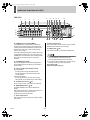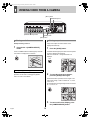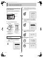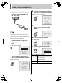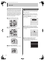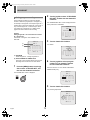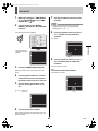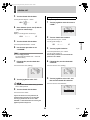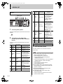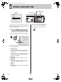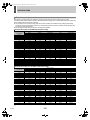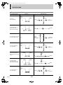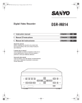
1
e00_l8hbg_us_7.book Page 1 Thursday, November 25, 2004 1:44 PM z Refer to the included CD-ROM for the French and Spanish “INSTRUCTION MANUAL”. z Utilisez le CD-ROM fourni pour consulter le “MANUEL D’INSTRUCTIONS” en français et en espagnol. z Consulte en el CD-ROM el “MANUAL DE INSTRUCCIONES” en francés y en español. e00_l8hbg_us_7.book Page 1 Thursday, November 25, 2004 1:44 PM PRECAUTION Declaration of Conformity CAUTION Model Number Trade Name Responsible party Address : DSR-3716/3709 : SANYO : SANYO FISHER COMPANY : 21605 Plummer Street, Chatsworth, California 91311 Telephone No. : (818) 998-7322 z This device complies with Part 15 of the FCC Rules. Operation is subject to the following two conditions: (1) this device may not cause harmful interference,and (2) this device must accept any interference received, including interference that may cause undesired operation. RISK OF ELECTRIC SHOCK DO NOT OPEN CAUTION: TO REDUCE THE RISK OF ELECTRIC SHOCK, DO NOT REMOVE COVER (OR BACK). NO USER-SERVICEABLE PARTS INSIDE. REFER SERVICING TO QUALIFIED SERVICE PERSONNEL. WARNING: To reduce the risk of fire or electric shock, do not expose this appliance to rain or moisture. CAUTION: Changes or modifications not expressly approved by the manufacturer may void the user’s authority to operate this equipment. The lightning flash with arrowhead symbol, within an equilateral triangle, is intended to alert the user to the presence of uninsulated “dangerous voltage” within the product’s enclosure that may be of sufficient magnitude to constitute a risk of electric shock to persons. Location For safe operation and satisfactory performance of your unit, keep the following in mind when selecting a place for its installation: z Shield it from direct sunlight and keep it away from sources of intense heat. z Avoid dusty or humid places. z Avoid places with insufficient ventilation for proper heat dissipation. Do not block the ventilation holes at the top and bottom of the unit. Do not place the unit on a carpet because this will block the ventilation holes. z Install the unit in a horizontal position only. z Avoid locations subject to strong vibrations. z Avoid moving the unit between cold and hot locations. z Do not place the unit directly on top of a monitor TV, as this may cause playback or recording problems. The exclamation point within an equilateral triangle is intended to alert the user to the presence of important operating and maintenance (servicing) instructions in the literature accompanying the product. This equipment has been tested and found to comply with the limits for a Class B digital device, pursuant to part 15 of the FCC Rules. These limits are designed to provide reasonable protection against harmful interference in a residential installation. This equipment generated, uses and can radiate radio frequency energy and, if not installed and used in accordance with the instructions, may cause harmful interference to radio communications. However, there is no guarantee that interference will not occur in a particular installation. If this equipment does cause harmful interference radio or television reception, which can be determined by turning the equipment off and on, the user is encouraged to try to correct the interference by one or more of the following measures: z Reorient or relocate the receiving antenna. z Increase the separation between the equipment and receiver. z Connect the equipment into an outlet on a circuit different from that to which the receiver is connected. z Consult the dealer or an experienced radio/TV technician for help. Avoiding Electrical Shock and Fire z Do not handle the power cord with wet hands. z Do not pull on the power cord when disconnecting it from an AC wall outlet. Grasp it by the plug. z If any liquid is spilled on the unit, unplug the power cord immediately and have the unit inspected at a factoryauthorised service centre. z Do not place anything directly on top of this unit. SERVICE This unit is a precision instruments and if treated with care, will provide years of satisfactory performance. However, in the event of a problem, the owner is advised not to attempt to make repairs or open the cabinet. Servicing should always be referred to your dealer or Sanyo Authorized Service Centre. For the customers in Canada This class B digital apparatus complies with Canadian ICES-003. CAUTION Licensed Under U.S. Patent No. 4,974,088 Danger of explosion if battery is incorrectly replaced. Replace only with the same or equivalent type recommended by the manufacturer. Discard used batteries according to the manufacture’s instructions. English 1 e00_l8hbg_us_7.book Page 2 Thursday, November 25, 2004 1:44 PM INTRODUCTION Main features Accessories The digital video recorder records video from monitoring cameras to its internal hard disk, it can display the video being displayed on a monitor split into four, nine or sixteen screens, and it can also display recorded video in the same way. Check that you have all the parts shown below. Power cord The DSR-3709 can only display split screen video in four or nine screens. Core clamp 1 large, 1 small z Large core clamp For LAN cable z Small core clamp For RS-485 cable Separately-sold hard disks (80, 160, 250, or 300 GB) can be installed to further increase this large memory capacity. Complete range of recording and playback functions Power cord tie z Simultaneous recording and playback of video. z Timer recording allows recordings to be made at different times each day. z Zoom allows a certain section of live and playback video to be magnified. z Alarm recording allows the actions of intruders to be recorded. z The video from specific cameras can be masked using a gray pattern to prevent it being monitored. z Motion sensing can be used with each camera, and alarms can be setup to give priority to the recording of moving images. z By connecting multiple digital video recorders, it is possible to perform analog series recording in which, once the capacity of one hard disk is reached, recording continues automatically on the next digital video recorder. z Instruction Manual (DVR) z Manual for Remote Operation by Network Connection z Quick Guide z CD-ROM Manual Symbols used in this manual Search function - lets you instantly display the desired recording. (JP.30) Information describing operation methods or how to get the most out of functions. z Searching in order of alarm occurrence using alarm search z Searching by thumbnail using alarm search z Searching by date/time z Searching within the archive area z Searching for intruder motion using motion detection search Information describing the correct use of the digital video recorder. (JP. xx) indicates the page to be referred to. Copyright Two-level security lock function - lets you restrict users for data and equipment management. (JP.89) z This manual and software are copyrighted by Sanyo Electric Co., Ltd. z Brand and product names used in this manual are the trademarks or registered trademarks of their respective companies. Expandable, can be connected to a PC z Recorded video can be copied to CompactFlash cards and CD-R/RW. z A built-in LAN terminal provides support for network control, thus facilitating live monitoring, camera control, playback, searches, and menu setting. z Monitoring can be carried out on two different monitor screens - namely, the main monitor and monitor 2. In addition, the main monitor can be viewed in splitscreen mode while the monitor 2 is used for full screen viewing or automatic camera selection. z Dome cameras can be controlled by button operations on the digital video recorder. z Images stored on a CompactFlash card can be printed directly from a printer. Except for personal use, copyright law prohibits the use of recorded copyrighted images without the permission of the copyright holder. 2 English e00_l8hbg_us_7.book Page 3 Thursday, November 25, 2004 1:44 PM CONTENTS INTRODUCTION 1 BEFORE USE .................................................5 3 INSTALLATION AND CONNECTIONS ...... 11 Notes on handling the internal HDD ...............5 Notes on installation locations ........................5 The hard disk and cooling fan are consumable components. ...................................................6 Important recordings .......................................6 Protection of the hard disk ..............................6 Backup battery ................................................6 Basic connections ........................................ 11 Connecting RS-485 terminals ...................... 11 Connecting SANYO protocol devices (Dome Cameras) .......................................... 13 Connecting an amplifier ............................... 13 Connecting ALARM IN terminals ................. 13 Connecting SENSOR ALARM OUT terminals ....................................................... 14 Connecting CONTROL terminals ................. 14 Connecting the power cord .......................... 14 2 NAMES AND FUNCTIONS OF PARTS .........7 Front panel ......................................................7 Rear panel ....................................................10 OPERATION 1 PREPARING FOR USE ................................15 5 SEARCHING FOR RECORDED VIDEO ..... 30 Operation display area ..................................15 Changing the position of the operation display area ...................................................16 Changing the language .................................16 Setting the time .............................................17 The internal hard disk ...................................18 Alarm search ................................................ 31 Alarm thumbnail search ............................... 32 Time/date search ......................................... 32 Archive area search ..................................... 34 Motion detection search ............................... 34 6 SAVING (COPYING) RECORDED VIDEO ..... 38 2 VIEWING VIDEO FROM A CAMERA ..........19 Copying video to the hard disk’s archive area ................................................. 39 Copying video to a CompactFlash card or Microdrive ..................................................... 41 Printing images from CompactFlash cards (quick print) .................................................. 43 Copying video to CD-R/RW ......................... 45 Viewing on a full screen ................................19 Viewing on quad screens ..............................19 Viewing on multi screens (9 screens/ 16 screens) ................................20 Viewing on plus screen .................................20 Viewing with automatic screen selection ......21 Viewing on the monitor 2 ..............................21 3 RECORDING ................................................23 Normal recording ..........................................23 Timer recording .............................................23 Alarm recording .............................................24 Pre-alarm recording ......................................25 4 PLAYBACK ..................................................26 Playing video on a full screen .......................26 Fast-forward and fast-rewind playback .........26 Changing the playback speed .......................27 Enlarging the playback video ........................27 Viewing still images .......................................28 Performing frame advance (forward or reverse) ......................................29 Playing video on multiple screens .................29 English 3 e04_l8hbg_us_7TOC.fm Page 4 Monday, November 29, 2004 2:30 PM CONTENTS INTRODUCTION SETTINGS 4 GENERAL SET ............................................ 86 1 MENU CONFIGURATION AND OPERATIONS ..............................................47 2 INITIAL SET .................................................51 Initial settings ................................................51 Setting the time .............................................51 Setting the daylight saving ............................51 External clock setting ....................................53 Detecting connected cameras ......................54 Setting camera titles .....................................55 Setting holidays .............................................56 Setting time periods ......................................57 OPERATION General settings ........................................... 86 Setting data display ...................................... 86 Setting display for video loss ........................ 87 Setting the buzzer ........................................ 88 Setting the security lock ............................... 89 Setting and initializing the hard disk ............. 92 Expanding the hard disk capacity ................ 93 Network settings ........................................... 93 Setting RS-485 ............................................. 96 Setting camera control ................................. 97 Basic menu operations .................................47 Restoring menu setting items to their default values ........................................48 Sub-menu configuration ................................49 5 SCREEN SET ............................................ 100 3 RECORD SET ..............................................60 Settings for recording ....................................60 Normal recording easy setup ........................60 Displaying the recording areas .....................64 Changing recording areas .............................65 Setting overwrite permission .........................66 Setting recording conditions ..........................67 Setting series recording ................................69 Setting auto deleting .....................................71 Setting normal recording ...............................71 Setting program recording ............................73 Timer settings ...............................................74 Setting alarm recording .................................77 Setting the motion sensors ...........................81 Setting alarm operation and display ..............84 Canceling alarms ..........................................85 SETTINGS Setting quad, multi 9 and 16 display .......... 100 Setting the period and monitors for automatic screen selection ......................... 102 Setting masks ............................................. 104 Setting the color level ................................. 105 6 POWER LOSS/USED TIME ...................... 107 OTHER 7 INITIALIZATION LOG ............................... 108 8 COPY MENU SETTINGS .......................... 109 Saving menu settings on a CompactFlash card .................................... 109 Loading settings from a CompactFlash card .................................... 110 OTHER 1 INTERFACE SPECIFICATIONS ................111 3 MENU SETTING SEQUENCE ................... 121 RS-485 specifications .................................111 SANYO protocol command table ................112 INDEX .............................................................. 123 2 SPECIFICATIONS ......................................113 Specifications ..............................................113 Dimensions .................................................114 UL disclaimer statement .............................114 Table of recording rate and times ...............115 Table of recording rate settings ..................117 Table of pre-alarm recording times .............118 Terminal board specifications .....................119 4 English e00_l8hbg_us_7.book Page 5 Thursday, November 25, 2004 1:44 PM 1 BEFORE USE Notes on handling the internal HDD Notes on replacing the HDD This digital video recorder uses an internal hard disk drive (HDD). Be sure to observe the following points carefully when operating, setting-up, or servicing the digital video recorder. Be sure to follow the correct procedure when replacing the HDD. z HDDs that have been removed from their packing may not operate correctly if they are subjected to sudden impact or vibration. It is recommended that you place the HDD on a soft, level surface with the printed circuit board facing upward after it has been unpacked. z Take care to avoid subjecting the HDD to sudden impact or vibration when removing and tightening screws as part of the HDD replacement procedure. Tighten all screws securely to ensure that they do not loosen. z The HDD is sensitive to static electricity; accordingly, you should take the appropriate precautions to prevent the buildup of static charges. Do not subject the digital video recorder to sudden impact or vibration. If the digital video recorder is subjected to sudden impact or vibration, it may damage the HDD or cause corruption of the data stored within it. z Do not move the digital video recorder while the power is turned on. Always ensure that the power is turned off before removing the digital video recorder from or placing it in a rack. z When transporting the digital video recorder, pack it securely using the specified materials. In addition, choose a method of transportation that minimizes vibration. z When placing the digital video recorder on the floor or another similar surface, attach the specified pads to its base and place it down gently. Handling a detached HDD unit If transporting or storing the HDD unit in a detached condition, be sure to first of all pack it using the specified materials. In addition, choose a method of transportation that minimizes vibration. Notes on installation locations Do not move the digital video recorder for 30 seconds after turning off the power. The hard disk is sensitive to dust, sudden impact, and vibration; furthermore, it should not be used near magnetic objects. The following precautions should be observed in order to prevent the loss of recorded data: z Do not subject the digital video recorder to sudden impact. z Do not use the digital video recorder on a vibrating or unstable surface. z Do not disconnect the power plug from the wall outlet during recording or playback. z Do not use the digital video recorder in areas with extreme temperature changes (i.e., 10ºC or more per hour). z Condensation may occur if the digital video recorder is moved to an area with a significantly different temperature or high humidity. If the digital video recorder is used while condensation is present inside it, operating problems may occur. z Do not install the digital video recorder inside motor vehicles, trains, or other areas under constant vibration. z The digital video recorder has ventilation holes on its left, rear, and bottom panels. Ensure that these holes are not blocked after installation. z Do not use the digital video recorder in a bookshelf, box, or any other area with poor ventilation. z This digital video recorder is designed for use in a horizontal orientation, and vertical setup may result in malfunction. z When installing the digital video recorder in a rack, ensure that a gap of at least 5 cm is provided at the top and bottom. After the power is turned off, the disk inside the HDD will continue to spin for a brief period due to inertia, and the heads will be in an unstable condition. During this period, the digital video recorder is even more susceptible to damage from sudden impact and vibration than when it is turned on. Make sure that the digital video recorder is not subjected to even gentle vibration for at least 30 seconds after turning off the power. Do not operate the digital video recorder when condensation has formed on it. If the digital video recorder is operated in this type of condition, there is a possibility that it will be permanently damaged. If the temperature around the digital video recorder changes suddenly, wait for it to stabilize before operating the digital video recorder. English 5 e00_l8hbg_us_7.book Page 6 Thursday, November 25, 2004 1:44 PM 1 BEFORE USE INTRODUCTION The hard disk and cooling fan are consumable components. If used in an ambient temperature of 25ºC, the hard disk should generally be replaced after 2 years; and the cooling fan after 3 years. These figures are intended as a general guideline only and should not be taken as a guarantee of component performance. The POWER indicator will flash if a problem occurs with the hard disk or fan. (JP.7) Important recordings z Always perform test recording in advance to confirm whether the digital video recorder’s playback is normal. z Note that Sanyo will accept no responsibility for losses occurring as a result of recording or playback problems caused by malfunction of this digital video recorder or any connected devices. z As a precaution against malfunction or accidents, it is advisable to periodically back up important recordings or to perform mirroring. Protection of the hard disk The hard disk is checked automatically when the power is turned on. If an abnormality is detected, the POWER indicator will begin to flash or an error message will be displayed. If you need initialize the hard disk or to save images stored on it, contact the dealer from whom you purchased this digital video recorder. Backup battery The digital video recorder comes with a built-in lithium battery. If power is supplied continuously for at least 48 hours after setting the date and time, the clock will continue to operate normally for up to 30 days without a supply of power. When disposing of this digital video recorder, contact the dealer from whom it was purchased for information on how to dispose of the lithium battery. 6 English e00_l8hbg_us_7.book Page 7 Thursday, November 25, 2004 1:44 PM 2 NAMES AND FUNCTIONS OF PARTS DSR-3716 1 2 3 4 8 5 7 9 15 12 MENU 13 14 16 17 EXIT/OSD 24 SHUTTLE PLAY/STOP C POWER 27 FULL AUDIO ALARM FULL LOCK MENU ALARM 1 2 3 4 5 6 7 8 9 10 11 12 13 14 15 16 QUAD MULTI PRESET MON 2 AUTO PAN PLUS SEQUENCE TOUR OUT 28 VIDEO 29 USB ZOOM FUNC. ENTER SEARCH AR LE 10 Front panel CARD IRIS SEQUENCE COPY SHUTTLE HOLD REC/STOP TIMER 18 21 25 ER FOCUS ALARM MENU MENU RESET PAN 19 22 23 EJECT 26 20 6. [CAMERA SELECT] buttons and indicators When one or more cameras have been connected to the VIDEO IN terminals on the digital video recorder’s rear panel and the appropriate [CAMERA SELECT] button is pressed, the corresponding indicator lights up and the video feed from that camera is displayed on-screen. z During quad, multi 9 or 16 screen display: The indicators corresponding to the cameras being displayed on the monitor are lit up. z If video is lost: The indicator starts to flash. z If an alarm occurs: The indicator for the corresponding camera starts to flash. 1. POWER indicator The POWER indicator will light up when the power is turned on. If the internal HDD or fan begins to malfunction, this indicator will be flashed. 2. FULL indicator (JP.68) The FULL indicator will begin to flash when the amount of available memory in the hard disk’s normal recording area drops to the percentage specified using menu settings. In addition, recording will stop automatically when no more memory is available, and the FULL indicator will switch to a permanently lit condition. This indicator can then be turned off by performing “AREA FULL RESET” using menu settings. 7. [FUNC.] button and indicator (JP.99) Switch to normal mode or camera control mode. Press button for camera control mode and indicator will light. Press button again to return to normal mode. Indicator turns off. 3. ALARM FULL indicator (JP.68) The ALARM FULL indicator will begin to flash when the amount of available memory in the hard disk’s alarm recording area drops to the percentage specified using menu settings. In addition, recording will stop automatically when no more memory is available, and the ALARM FULL indicator will switch to a permanently lit condition. This indicator can then be turned off by performing “AREA FULL RESET” using menu settings. 8. [QUAD] button and indicator (JP.19) The [QUAD] button is used to display video in quad screens, and the indicator will light up when this type of display is being presented. The QUAD indicator will turn off when a different screen display mode is adopted. 9. [MULTI] button and indicator (JP.20) The [MULTI] button is used to display video in multi 9 or 16 screens, and the indicator will light up when this type of display is being presented. The MULTI indicator will turn off when a different screen display mode is adopted. The DSR-3709 can only display video in nine screens. 4. LOCK indicator (JP.91) The LOCK indicator lights up when operation has been locked using <SECURITY LOCK SET>. An alarm will be sounded if a button is pressed in this condition. In addition, a password entry screen will be displayed on the monitor at this time. If the correct administrator password is entered, the lock condition will be cancelled and the LOCK indicator will turn off. 10. [MON2] button and indicator (JP.21) If the [MON2] button is pressed while a monitor is connected to the MON2 output terminal on the rear panel, it will be possible to change the monitor 2 output video. The [CAMERA SELECT] and [SEQUENCE] buttons can be used, and the indicator will be lit up during the setting procedure. 5. ALARM indicator The ALARM indicator flashes during alarm recording, and it is lit up during pre-alarm recording. English 11 EN T STILL ZOOM/I/FO 6 JOG AF 7 e00_l8hbg_us_7.book Page 8 Thursday, November 25, 2004 1:44 PM 2 NAMES AND FUNCTIONS OF PARTS 8 2 1 3 4 7 5 9 15 12 MENU 13 14 16 17 EXIT/OSD 24 SHUTTLE PLAY/STOP C POWER 27 28 29 FULL 1 ALARM FULL 2 3 4 LOCK 5 MENU ALARM 6 7 8 9 QUAD MULTI VIDEO PRESET MON 2 AUTO PAN PLUS USB SEQUENCE TOUR AUDIO ZOOM FUNC. OUT ENTER SEARCH AR LE 10 11 ER 25 CARD IRIS COPY SHUTTLE HOLD REC/STOP TIMER 21 EN T STILL SEQUENCE 18 JOG AF FOCUS ALARM ZOOM/I/FO 6 INTRODUCTION DSR-3709 MENU RESET PAN EJECT 26 19 22 23 20 17. [STILL] button and indicator (JP.28) When the [STILL] button is pressed during playback, the current frame is displayed as a still image and the indicator lights up. Playback can be resumed by pressing this button once again. 11. [PLUS] button and indicator (JP.20) The [PLUS] button is used to enlarge video from a single camera to quad screen size during multi 9 or multi 16 screen display. For DSR-3709, this operation is available only when in multi 9 screen display. 18. [SEQUENCE] button and indicator (JP.21) The [SEQUENCE] button can be pressed during monitoring to automatically switch between screen display. When pressed, the indicator begins flashing and the display is changed automatically. The lighting condition of CAMERA SELECT indicators also changes in response to the screen display. 12. [MENU] button and indicator The [MENU] button is used to display the menu screens (i.e., setting screens), and the indicator lights up while any of these screens is being displayed. 13. [EXIT/OSD] button and indicator z EXIT The [EXIT/OSD] button is used to exit the main menu or a sub-menu. When a menu is displayed, the indicator turns off; when the menu is closed and the normal display is restored, the indicator lights up. z OSD (JP.16) Each time the [EXIT/OSD] button is pressed while the digital video recorder is recording, playing, or stopped, the operating display location moves in the order of top of screen, bottom of screen, to hidden; furthermore, the indicator lights up when this information is being displayed. 19. [COPY] button and indicator (JP.39) The [COPY] button is used to copy recorded video to the hard disk’s archive area, to a CompactFlash card, CD-R/ RW or to a Microdrive. The indicator lights up during the copy process. 20. [SHUTTLE HOLD] button and indicator (JP.26) The [SHUTTLE HOLD] button is used to lock shuttle dial operation for a constant speed of playback or slow playback. The indicator lights up while the shuttle dial is locked. When a password has been set, furthermore, this button can be pressed for at least three seconds to activate the security lock. 14. [PLAY/STOP] button and indicator (JP.26) When the [PLAY/STOP] button is pressed, a recording from the normal recording area or alarm recording area is played and the indicator lights up. When pressed during playback, this button stops the digital video recorder. 21. [REC/STOP] button and indicator (JP.23) The [REC/STOP] button is pressed to start normal recording, and the indicator lights up during this process. Furthermore, pressing this button for at least three seconds stops recording and turns off the indicator. 15. [ZOOM] button and indicator (JP.19, 27) When the [ZOOM] button is pressed during monitoring or playback on a full screen, a portion of the playback video is magnified and the indicator lights up. 16. [SEARCH] button and indicator (JP.31) When the [SEARCH] button is pressed while the digital video recorder is recording or stopped, the search menu is displayed and the indicator lights up. The search menu can be closed by pressing this button once again. 8 English e00_l8hbg_us_7.book Page 9 Thursday, November 25, 2004 1:44 PM 2 NAMES AND FUNCTIONS OF PARTS DSR-3716 1 2 3 4 8 5 7 9 15 12 MENU 13 14 16 17 EXIT/OSD 24 SHUTTLE PLAY/STOP C POWER 27 FULL AUDIO ALARM FULL LOCK MENU ALARM 1 2 3 4 5 6 7 8 9 10 11 12 13 14 15 16 QUAD MULTI PRESET MON 2 AUTO PAN PLUS SEQUENCE TOUR OUT 28 VIDEO 29 USB ZOOM FUNC. ENTER SEARCH AR LE 10 CARD IRIS SEQUENCE COPY SHUTTLE HOLD REC/STOP TIMER 18 21 25 ER FOCUS ALARM MENU MENU RESET PAN 19 22 23 EJECT 26 20 28. Video output terminal This terminal outputs the same video as that of the MAIN MONITOR output terminal on the rear panel. 22. [TIMER] button and indicator (JP.23) If the [TIMER] button is pressed while the recording is stopped, timer recording standby mode is adopted and recording will then start automatically at the set time. The indicator will be lit up while in timer recording standby mode or timer recording. If the button is pressed during timer recording, this process is stopped and the indicator turns off. Furthermore, if the [TIMER] button is pressed when in timer recording standby mode, indicator is turned off and timer recording is cancelled. 29. USB terminal (JP.45) This terminal connects to a recordable CD-R/RW drive. z The USB terminal is for the use of the recommended Sanyo CD-R/RW drive (sold separately). Nonrecommended peripherals cannot be connected. z For recommended recordable drives, check the Sanyo homepage or ask at your local Sanyo dealer. Sanyo website URL: http://www.sanyosecurity.com 23. [ALARM] buttons (JP.31) When an [ALARM] button is pressed during playback or still, the digital video recorder skips to the next earlier or next later alarm. 24. Jog dial (inside) and shuttle dial (outside) z During playback: Use the jog dial to change the playback speed. Use the shuttle dial to perform fast-forward or fastreverse playback. z During menu display: Use the jog dial to move the cursor and to change setting values. Use the shuttle dial to confirm settings. 25. CompactFlash card slot (JP.41) This slot is used to house a CompactFlash card or Microdrive. 26. [MENU RESET] button (JP.48) The [MENU RESET] button is used to default menu settings. When setting motion sensors, furthermore, all sensors on the same line as the cursor can be turned on simultaneously by pressing this button. 27. Audio output terminal Audio output is the same as that of the rear panel AUDIO OUT terminal. English 11 EN T STILL ZOOM/I/FO 6 JOG AF 9 e00_l8hbg_us_7.book Page 10 Thursday, November 25, 2004 1:44 PM 2 NAMES AND FUNCTIONS OF PARTS (The number of terminals for the DSR-3709 may differ. For more details, see below.) INTRODUCTION DSR-3716 17 14 AC IN 1 2 1 3 4 5 6 7 8 9 10 11 12 13 14 15 16 ALARM IN C 1 2 3 4 5 6 7 8 9 10 11 12 13 14 15 16 IN C 1 2 3 4 5 6 7 8 9 10 11 12 13 14 15 16 2 18 AUDIO IN OUT MIC IN MONITOR OUT MAIN MON2 USB LAN ALL RESET RS-485 TERMINATE OFF ON A RS-485 B SENSOR ALARM OUT OUT REC NON ER IN TIM EXIT OUT IES SER IES IN SER ULL F RM ALA FULL OUT NING WAR RESET RM ALA M OUT R ALA OUT CK CLO CK IN CLO OUT REMOTE C R1 R2 DO NOT CONNECT TO PHONE LINE 3 4 5 6 7 8 9 10 16 15 16. CONTROL terminals Pin 1. VIDEO IN terminals The DSR-3709 has nine VIDEO IN terminals. 2. VIDEO OUT terminals The DSR-3709 has nine VIDEO OUT terminals. 3. [ALL RESET] button When the [ALL RESET] button is pressed, the digital video recorder is reset and the time is returned to its default setting. 4. CONTROL 11 12 13 Rear panel C AUDIO IN terminal 5. AUDIO OUT terminal 6. MIC IN terminal 7. MAIN MONITOR output terminal 8. MON2 output terminal 9. USB terminal This terminal connects to a recordable CD-R/RW drive. 10. LAN terminal (10 Base-T or 100 Base-TX) 11. RS-485 termination switch Signal C Ground REMOTE R1 Remote input 1 REMOTE R2 Remote input 2 CLOCK SET IN Input of a clock setting signal from an external device CLOCK SET OUT Output of a clock setting signal to an external device ALARM OUT Total alarm output ALARM RESET Alarm reset input WARNING OUT Output of an HDD or FAN malfunction error FULL Capacity warning output for normal recording area space ALARM FULL Capacity warning output for alarm recording area space SERIES IN Signal input from an analog series connection SERIES OUT Signal output to an analog series connection EXT TIMER IN Signal input from an external timer 12. RS-485 terminal (A) NON REC OUT Non-recording output 13. RS-485 terminal (B) C Ground 14. ALARM IN terminals These terminals are used to activate alarm recording in response to operation of an alarm switch on a connected device. The DSR-3709 has nine ALARM IN terminals. Pin 17. Power socket (AC IN) Insert the supplied power cable securely into this socket. 18. Power cord holder Secure the power cord to the holder using the cord tie (accessory) as shown in the illustration. Signal C Ground ALARM IN 1 to 16 Alarm input No. 1 through No. 16 15. SENSOR ALARM OUT terminals The terminals are used when motion sensors have been set (JP.81) to output an alarm signal to a connected device upon detection of motion. The DSR-3709 has nine SENSOR ALARM OUT terminals. Pin Signal C Ground SENSOR ALARM OUT 1 to 16 Output of an alarm signal for Camera No. 1 through No. 16 10 English e05_l8hbg_us_7.fm Page 11 Thursday, November 25, 2004 3:01 PM 3 INSTALLATION AND CONNECTIONS This section describes how to connect the digital video recorder to video cameras and other devices. Be sure to read the instruction manuals for each connected device. z Improper connections can result in malfunction or the emission of smoke. z A separate power supply is required for operation of each camera. Basic connections The following diagram shows the connections for cameras, monitors, a microphone, and a PC. DSR-3716 System controller (sold separately) VSP-8000/9000 The DSR-3709 can be connected to nine cameras. Camera (sold separately) (1-16) The RS-485 connector is connected to A or B according to the type of cable. *2 Wrap the cable once around the small core clamp to attach it. AC IN 1 2 3 4 5 6 7 8 9 10 11 12 13 14 15 16 ALARM IN C 1 2 3 4 5 6 7 8 9 10 11 12 13 14 15 16 IN OUT C 1 2 3 4 5 6 7 8 9 10 11 12 13 14 15 16 AUDIO IN OUT MONITOR OUT MAIN MON2 MIC IN LAN USB ALL RESET RS-485 TERMINATE OFF ON A RS-485 B SENSOR ALARM OUT O UT REC NON ER IN TIM EXIT OUT IES SER IES IN SER ULL F RM ALA FULL OUT NING WAR RESET RM ALA M OUT R ALA OUT CK CLO CK IN CLO Microphone (sold separately) REMOTE C R1 R2 DO NOT CONNECT TO PHONE LINE Video input terminal 01 02 03 04 Monitor (sold separately) Video input terminal Monitor 2 (sold separately) C CONTROL 120 V-240 V AC (50/60 Hz) *1 Wrap the cable once around the large core clamp to attach it. PC * If the monitor 2 (MON2) is not synchronized with the connected cameras, vertical picture instability may occur upon the switching of camera video. Connecting RS-485 terminals z Do not connect to phone line. The RS-485 terminals are used to connect a system controller (sold separately) to the digital video recorder. After connecting the system controller, you will need to carry out the settings that are given in the <RS-485 SET> menu. (JP.96) Pin locations 1 English Pin number Connector A signal Connector B signal 1 Not used Not used 2 Not used Not used 3 A B 4 B A 5 Not used Not used 6 Not used Not used A: Non-inverting driver output/receiver input B: lnverting driver output/receiver input 6 11 e00_l8hbg_us_7.book Page 12 Thursday, November 25, 2004 1:44 PM 3 INSTALLATION AND CONNECTIONS Connection INTRODUCTION RS-485 termination switch settings The digital video recorder supports both straight type and crossed type connection cables. When using a straight type connection cable, connect the RS-485 connector’s pin A to the pin A socket, or pin B to the pin B socket. When using a crossed type connection cable, connect the RS-485 connector’s pin A to the pin B socket, or pin B to the pin A socket. When connecting multiple devices, you must make termination settings on both end devices. z Set the RS-485 termination switch of both end devices to ON. z Be sure to set the RS-485 termination switches of all devices in between (devices other than the first and last devices) to OFF. A RS485 B z If you don’t make the correct termination settings, the incorrect data will be transmitted to each device. DO NOT CONNECT TO PHONE LINE To other connector A To other connector A Example System controller Straight type cable Crossed type cable Cable types Straight type: ON 1 2 3 4 5 6 Not used Not used Not used Not used 1 2 3 4 5 6 Termination switch OFF Crossed type: 1 2 3 4 5 6 Not used Not used Not used Not used 1 2 3 4 5 6 Digital video recorder OFF ON RS-485 termination switch Time-lapse VCR ON OFF 12 Termination switch English e00_l8hbg_us_7.book Page 13 Thursday, November 25, 2004 1:44 PM 3 INSTALLATION AND CONNECTIONS Connecting SANYO protocol devices (Dome Cameras) Connecting an amplifier An amplifier is connected when using a microphone or external speakers with the digital video recorder. Turn off all devices and use a coaxial cable to connect the devices. z Use the same procedure to connect using PELCO and BBV. Audio input Amp (sold separately) Audio output AUDIO IN OUT IN OUT Camera 1 2 3 Connect cameras to the VIDEO IN terminals. z Audio input from the AUDIO IN terminal and the MIC IN terminal cannot be performed simultaneously. If both terminals have devices connected, the MIC IN terminal is used. Set the protocols and address in the <CAMERA CONTROL SET> screen. (JP.97) Connecting ALARM IN terminals Operate the dome cameras with the front panel buttons. (JP.99) When using external alarms (i.e., intruder sensors and the like), external switches are to be connected to the ALARM IN terminals. 16 Connecting ALARM IN terminals to external switches 1 C 1 2 3 4 5 6 7 8 9 10 11 12 13 14 15 16 The DSR-3709 has nine ALARM IN terminals. English 13 e00_l8hbg_us_7.book Page 14 Thursday, November 25, 2004 1:44 PM 3 INSTALLATION AND CONNECTIONS Connecting the power cord 1 The SENSOR ALARM OUT terminals are used to relay alarm signals whenever one of the digital video recorder’s motion sensors is triggered. Normally in an open condition, a terminal adopts low condition when a sensor for the corresponding camera number has been triggered. When you have finished making all the other connections, make sure the voltage is 120 V-240 V AC and insert the power plug into the wall outlet. There is no power switch. The display indicators flash, and after a few moments, the monitor screen displays the camera image. Rating for each terminal z Maximum current: 25 mA z Maximum voltage: 25 V 1K INTRODUCTION Connecting SENSOR ALARM OUT terminals 120 V-240 V AC (50/60 Hz) Connecting CONTROL terminals The connections for a remote control circuit are shown below. This digital video recorder can be remotely controlled when a remote-control circuit similar to that shown here is connected to the remote-input control terminals. z When turning the power on for the first time “PLEASE SET THE CLOCK” is displayed on the monitor screen. Follow the procedures on P.17 to set the clock. z If the clock is already set The operation display area is displayed. Operation display area C R1 0 01-01-04 00:00:00 REC REPEAT EN A ALARM 0000 R2 02 R1 R2 (When operated (When combined independently) with R2 Shift key) SW 1 : Camera 1*: INDEX + SW 17 : REC/STOP SW 2 : Camera 2*: INDEX - SW 18 : PLAY/STOP SW 3 : Camera 3*: AUTO FOCUS SW 19 : STILL SW 4 : Camera 4*: SEQUENCE SW 20 : SEARCH SW 5 : Camera 5*: MON2 SW 21 : SHIFT (Doubles with R1) SW 6 : Camera 6*: PLUS SW 22 : PLAY SW 7 : Camera 7*: QUAD SW 23 : REC SW 8 : Camera 8*: MULTI SW 24 : MENU SW 9 : Camera 9*: MENU RESET SW 25 : EXIT/OSD SW 10 : Camera 10: SW 26 : + SW 11 : Camera 11: PAN left SW 27 : - SW 12 : Camera 12: PAN right SW 28 : → SW 13 : Camera 13: TILT down SW 29 : ← SW 14 : Camera 14: TILT up SW 30 : ZOOM SW 15 : Camera 15: ZOOM wide SW 31 : COPY SW 16 : Camera 16: ZOOM tele SW 32 : TIMER z If the POWER indicator starts flashing; If a problem occurs during use, the POWER indicator will begin to flash and an explanation will be displayed. In these cases, contact a Sanyo service center. POWER indicator status Meaning Four flashes per second There is a problem with the hard disk. The hard disk must be replaced or initialized. Contact a Sanyo service center to recover recorded images. One flash per second There is a problem with the fan. z The power cord’s ground terminal is not provided for enhanced safety; rather, it can be used to reduce the level of interference when the digital video recorder is connected to analog devices. If a large amount of noise is generated when the digital video recorder is connected to analog devices, connect this terminal to the building’s earth. z Use a resistance of 1/10 ohms or more and with a D ranking (Precision within ±0.5%). z The remote control cable should be no more than 5 m long. * The DSR-3709 can operate up to nine cameras (*). 14 English e00_l8hbg_us_7.book Page 15 Thursday, November 25, 2004 1:44 PM 1 PREPARING FOR USE (5) Picture quality display (JP.71) Displays the quality of the video that can be recorded on the hard disk. Set to “EN” (Enhanced) by default. Operation display area Whenever the power is turned on, the operation display area will be shown at the top of the monitor screen. This area indicates the date, time, picture quality, and other information needed for operation. BA 0 01-01-04 00:00:00 REC REPEAT EN A ALARM 0000 Basic NO Normal EN Enhanced FI Fine SF Super Fine (6) Audio recording display “A” is displayed when audio is being recorded or played back. (7) Alarm display and alarm count display (JP.77) When you set an alarm using the “ALARM REC MODE SET” menu item, the alarm display area presents the following information. z When alarm recording is set; “ALARM” is displayed. “ALARM” is flashed during alarm recording. z When pre-alarm recording is set; “PRE” is displayed. When an alarm occurs, “PRE” disappears, “ALARM” is displayed, and the number of alarms is shown. The total number is indicated in the alarm display. z When performing playback from the archive area; “ARCHIV” is displayed. z When an external alarm signal is activated; “EA” is flashed to the left of the camera number. z When a motion sensor alarm signal is activated; “SA” is flashed to the left of the camera number. z When an external alarm signal and motion sensor signal are activated; “ES” flashes to the left of the camera number. 02 (1) (2) (3) (4) (5)(6) (7) 01-01-04 00:00:00 REC REPEAT EN A ALARM 0000 02 (8) (1) Date display (JP.17) “01-01-04” (month-day-year) is displayed when you turn the power on for the first time. Be sure to specify the correct date using menu settings. (2) Time display (JP.17) “00:00:00” is displayed when you turn the power on for the first time. The digital video recorder uses the date and time to manage recording and playback points. Accordingly, if the time has not been set correctly, you will not be able to effectively search for video data. Make sure to specify the time using menu settings. Recording will not be possible until a setting has been made. (3) Operating symbol display Displays the current operation (such as recording or playback). REC: Recording EXT: External timer recording : Playback : Reverse playback : Still (8) Camera title display The camera number or camera title is displayed. In addition, when an alarm occurs, the camera number and alarm “EA”, “SA” or “ES” are displayed along with the camera title. z During video loss; The display alternates between showing the camera title and “VIDEO LOSS”. “VIDEO LOSS” flashes when the operating display is hidden. (JP.16) z During no video signal; “NO VIDEO” is displayed in place of the camera title. : Fast-forward playback : Fast-rewind playback : Slow playback : Reverse slow playback z During simultaneous recording and playback, the display indicates playback ( ). (4) Remaining memory in recording area (JP.67) Displays the remaining area memory as a percentage when overwriting in the normal recording area or the alarm recording area is forbidden. If overwriting has been permitted, “REPEAT” is displayed. z Although operations such as playback, copying, and data transfer are possible while recording, this unit gives priority to recording, and other operations may be delayed as a result. English 15 e00_l8hbg_us_7.book Page 16 Thursday, November 25, 2004 1:44 PM 1 PREPARING FOR USE [MENU] button [EXIT/OSD] button Shuttle dial CARD OPERATION MENU RESET EJECT [REC/STOP] button 1 Changing the position of the operation display area 1 MENU As the [EXIT/OSD] button is pressed, the operation display area moves to a different location or is hidden. 01-01-04 00:00:00 REC REPEAT EN A ALARM 0000 Bottom 01 Press the [MENU] button. The MENU indicator lights up and the <MAIN MENU> is displayed. Press the [EXIT/OSD] button. Top (default) Jog dial 02 <MAIN MENU> 1.INITIAL SET 2.RECORD SET 3.GENERAL SET 4.SCREEN SET 5.POWER LOSS/USED TIME 6.INITIALIZATION LOG 7.COPY MENU SETTINGS MOVE:JOG Hidden Operation display area 2 01-01-04 00:00:00 REC REPEAT EN A ALARM 0000 03 04 -> -> -> -> -> -> -> SELECT:SHUTTLE Turn the shuttle dial clockwise. The <INITIAL SET> screen is displayed. Changing the language <INITIAL SET> 1.LANGUAGE/CLOCK SET 2.CAMERA DETECT 3.TITLE SET 4.HOLIDAY SET 5.TIME PERIOD SET Use the following procedure to set the language displayed on the monitor. -> -> -> -> -> [Settings] ( indicates default setting) Item Setting ENGLISH LANGUAGE Description MOVE:JOG Sets the language to English. FRANCAIS Sets the language to French. 3 ESPAÑOL The cursor moves to “ENGLISH”. Sets the language to Spanish. SELECT:SHUTTLE Turn the shuttle dial clockwise. <LANGUAGE/LANGUE/IDIOMA> ENGLISH <CLOCK SET> 01-01-2004 THU 00:00:00 <DAYLIGHT SAVING> MODE : USE WEEK MONTH TIME ON 1ST-SUN 04 02:00 OFF LST-SUN 10 02:00 <EXT.CLOCK SET> ADJUST. TIME 01:00 16 English e00_l8hbg_us_7.book Page 17 Thursday, November 25, 2004 1:44 PM 1 4 PREPARING FOR USE 3 Turn the shuttle dial clockwise, and then turn the jog dial to select the desired language. Turn the shuttle dial clockwise. The <LANGUAGE/LANGUE/IDIOMA> screen is displayed. The set item flashes. <LANGUAGE/LANGUE/IDIOMA> ENGLISH <CLOCK SET> 01-01-2004 THU 00:00:00 <DAYLIGHT SAVING> MODE : USE WEEK MONTH TIME ON 1ST-SUN 04 02:00 OFF LST-SUN 10 02:00 <EXT.CLOCK SET> ADJUST. TIME 01:00 <REGL.LANGUE> FRANCAIS <REGL.HORLOGE> 01-01-2004 JEU 00:00:00 , <HEURE D ETE> MODE : MARCHE SEMAINE MOIS HEURE ON 1ER-DIM 04 02:00 OFF DER-DIM 10 02:00 <REGL.HORLOGE EXTERNE> , REGL.DE L HEURE 01:00 5 4 When you have made a selection, turn the shuttle dial clockwise. The cursor moves to the date and time. The language has now been set. To return to the normal screen, press the [EXIT/OSD] button. Turn the jog dial to select the date and time for <CLOCK SET> and turn the shuttle dial clockwise. “01” flashes (indicating the month). <LANGUAGE/LANGUE/IDIOMA> ENGLISH <CLOCK SET> 01-01-2004 THU 00:00:00 <DAYLIGHT SAVING> MODE : USE WEEK MONTH TIME ON 1ST-SUN 04 02:00 OFF LST-SUN 10 02:00 <EXT.CLOCK SET> ADJUST. TIME 01:00 EXIT/OSD Setting the time (Default: 01-01-2004 THU 00:00:00) Be sure to set the correct date and time as these settings are used during recording and searching. 5 Example: Setting 8:30 on October 26, 2004 1 MENU “01” flashes (indicating the day). <MAIN MENU> 1.INITIAL SET 2.RECORD SET 3.GENERAL SET 4.SCREEN SET 5.POWER LOSS/USED TIME 6.INITIALIZATION LOG 7.COPY MENU SETTINGS MOVE:JOG 10-01-2004 MON 00:00:00 6 -> -> -> -> -> -> -> SELECT:SHUTTLE 7 Turn the shuttle dial clockwise. <INITIAL SET> 1.LANGUAGE/CLOCK SET 2.CAMERA DETECT 3.TITLE SET 4.HOLIDAY SET 5.TIME PERIOD SET MOVE:JOG Use the same procedure to set the day (26), year (2004), hour (08), and minute (30). When you have set the minute, the cursor moves to “MODE” under <DAYLIGHT SAVING>, and the clock starts counting from 00 seconds. z The week day is set automatically. z The clock is stopped during date and time settings. The <INITIAL SET> screen is displayed. English Set “10” with the jog dial or numeric keys and turn the shuttle dial clockwise. Press the [MENU] button. The MENU indicator lights up and the <MAIN MENU> is displayed. 2 K Press the [EXIT/OSD] button. The setting procedure is ended and the display returns to the normal screen. -> -> -> -> -> EXIT/OSD SELECT:SHUTTLE 17 e00_l8hbg_us_7.book Page 18 Thursday, November 25, 2004 1:44 PM 1 PREPARING FOR USE [C] Archive area The internal hard disk Recording mode <RECORDING AREA SET> TOTAL CAPACITY : NORMAL RECORDING AREA : AREA FULL RESET -> ALARM RECORDING AREA : AREA FULL RESET -> ARCHIVE AREA : AREA FULL RESET -> [A] [B] [C] 82GB 80 % 19 % Copy 1% Hard disk recording areas z If the memory allocations for the various hard disk recording areas are changed during a recording process, all stored recordings will be deleted and the hard disk will be initialized; accordingly, special care should be taken. For more details, refer to P.65. z In the case of certain hard disks, error may be present in the total hard disk capacity as displayed on menu screens. When the digital video recorder is turned on, recording areas are automatically setup within the internal hard disk (with the default settings being normal recording area: 80%, alarm recording area: 19%, and archive area: 1%). When the [REC/STOP] button is pressed, this digital video recorder starts recording video data in the normal recording area. When an alarm occurs, the corresponding video data is recorded in the alarm recording area. area Manual This area is used to store important video data copied from the normal recording area and/or alarm recording area. By making changes to the normal recording area and the alarm recording area, this area can be extended to up to 10 GB in size (i.e., 12% when using a 80 GB hard disk). OPERATION CAUTION : WHEN THE AREA SETTING IS CHANGED, THE WHOLE AREA WILL BE INITIALIZED ! B Alarm recording Recording method C Archive area 1% 19% 80% A Normal recording area Hard Disk Recording Areas [A] Normal recording area Recording mode Recording method Normal recording Manual Timer recording Automatic When monitoring, recording is performed in response to pressing of the [REC/STOP] button. Recording is carried out in accordance with timer settings. [B] Alarm recording area Recording mode Recording method Alarm recording Automatic Pre-alarm recording Automatic Recording is carried out when alarm recording is set to “ENABLED”. Specifically, alarm images are recorded in the alarm recording area in response either to operation of a switch that has been connected to an alarm input terminal or to detection of an intruder or the like using motion sensors. When pre-alarm recording is set to “ON”, it will be possible to record video from before the occurrence of an alarm based on the corresponding settings. 18 English e00_l8hbg_us_7.book Page 19 Thursday, November 25, 2004 1:44 PM 2 VIEWING VIDEO FROM A CAMERA [MULTI] button [SEQUENCE] button CARD MENU RESET EJECT [CAMERA SELECT] buttons [PLUS] button [MON2] button [QUAD] button Viewing on a full screen Viewing on quad screens Images from multiple connected cameras can be displayed simultaneously. Example: Selecting Camera 2 1 Press the No. 2 [CAMERA SELECT] button. 1 Press the [QUAD] button. The QUAD indicator lights up and video from four separate cameras is displayed simultaneously. Video from Camera No. 1 through Camera No. 4 is displayed. The No. 2 CAMERA SELECT indicator lights up and video from Camera 2 is displayed on a full screen. QUAD 01 02 03 04 02 Viewing enlarged live images Images can be enlarged while monitoring on a full screen. Operations are the same as “Enlarging the playback video”. See P.27 for more details. 2 To view video from other cameras, press the [QUAD] button again. Each time this button is pressed, the four images on the quad screen change, in order of cameras No. 1-4, 5-8, 912 and 13-16. On the DSR-3709, the images change in order of cameras No. 1-4, 5-8, 9-3, etc. QUAD 3 English 19 05 06 07 08 To return to full screen display, press the [CAMERA SELECT] button. e00_l8hbg_us_7.book Page 20 Thursday, November 25, 2004 1:44 PM 2 VIEWING VIDEO FROM A CAMERA Viewing on multi screens (9 screens/ 16 screens) 1 Viewing on plus screen Enlarge one camera video to quad screen size to view in multi 6/13 screen display. For DSR-3709, this operation is available only when in multi 9 screen display. Press the [MULTI] button. 1 PLUS indicator lights and one camera image is enlarged. MULTI MULTI PLUS 01 02 03 04 05 06 07 08 13 14 09 15 16 2 z For both quad and multi 9/16 screen display, display positions can be changed. (JP.100) 2 Press the [PLUS] button. OPERATION The MULTI indicator lights up and video from nine separate cameras is displayed simultaneously. Press the [MULTI] button again to display video from 16 cameras. The DSR-3709 can only display video from nine cameras. 01 02 03 01 02 03 04 05 06 04 01 05 06 07 08 09 07 08 09 Press the corresponding [CAMERA SELECT] button to change enlarged camera image. The video from the selected camera is enlarged. To return to full screen display, press the [CAMERA SELECT] button. 01 04 02 07 3 02 03 05 06 08 09 Press [MULTI] button to switch from multi 6 screen display to multi 13 screen display. Operation can be performed solely with DSR-3716. MULTI 01 02 03 04 01 05 06 07 08 09 01 4 03 04 07 08 09 10 11 12 13 14 15 16 Press [PLUS] button to return to the previous display. z The time required for updating differs for each image. 20 English e00_l8hbg_us_7.book Page 21 Thursday, November 25, 2004 1:44 PM 2 VIEWING VIDEO FROM A CAMERA 2 Viewing with automatic screen selection The content of the split screen will automatically toggle between video from cameras No. 1 through No. 4 and video from cameras No. 5 through No. 8, No. 9 through No. 12 and No. 13 through No. 16 On the DSR-3709, the video changes automatically in order of cameras No. 1-4, 5-8, 9-3, etc. Setting automatic full screen selection Use the following procedure when viewing a full screen to have the displayed video change automatically based on camera numbers. 1 Press the [SEQUENCE] button. Press the [SEQUENCE] button. 02 01 The SEQUENCE indicator starts to flash and the displayed video changes automatically based on camera numbers. 04 03 08 07 12 11 15 16 Returning to normal quad-screen display 01-01-04 00:00:00 REC REPEAT EN A ALARM 0000 01 04-01-01 00:00:00 REC REPEATENA ALARM 0000 02 01-01-01 00:00:00 REC REPEATENA ALARM 0000 15 02-01-01 00:00:00 REC REPEATENA ALARM 0000 16 3 Press the [SEQUENCE] button once again. Automatic selection ends and normal quad-screen display returns. z It is possible to specify the cameras for which automatic selection is to be carried out. (JP.102) z Automatic selection cannot be used with playback video. Canceling automatic selection 2 Viewing on the monitor 2 Either press the [SEQUENCE] button once again or press the appropriate [CAMERA SELECT], [QUAD], or [MULTI] button. When a monitor 2 is connected to the monitor 2 output terminal on the digital video recorder’s rear panel, this monitor can be used to view video from a single camera or to automatically scroll through video from all cameras, even if the main monitor is currently displaying video in split-screen format. In addition, it is also possible to display video on the monitor 2 automatically from any camera for which an alarm has occurred. By default, automatic full screen selection is carried out. Automatic selection ends and the display returns to the normal screen. Setting automatic quad-screen selection 1 Press the [QUAD] button. Change the monitor 2 setting The QUAD indicator lights up and the monitor display is divided in four. 1 QUAD Press the [MON2] button. The MON2 indicator lights up. 01 MON2 02 CARD 03 04 MENU RESET EJECT [MON2] button English 21 e00_l8hbg_us_7.book Page 22 Thursday, November 25, 2004 1:44 PM 2 VIEWING VIDEO FROM A CAMERA z Monitor 2 operation is not possible when a menu screen is being displayed. z As the [EXIT/OSD] button is pressed, the operating display moves to a different location or is hidden in the same manner as the main monitor. (JP.16) z If the monitor 2 is not synchronized with the connected cameras, vertical picture instability may occur upon the switching of camera video. Displaying alarm video in full screen format 2 Press the No. 4 [CAMERA SELECT] button. Set “MON.2 DISPLAY” from <ALARM OPERATION SET> to “ON”. (JP.84) OPERATION 1 Selecting Camera No. 4 for full screen When an alarm occurs, the corresponding video is displayed in full screen format on the monitor 2. The video from Camera No. 4 is displayed in full screen format on the monitor 2. 01-01-04 00:00:00 CARD MENU RESET EJECT 02 Monitor 2 01-01-04 Main Monitor 00:00:00 Ending the monitor 2 setting procedure 03 01 04 07 1 06 08 Press the [MON2] button. The MON2 indicator turns off. 09 MON2 Setting automatic full screen selection 1 Press the [SEQUENCE] button. The video displayed on the monitor 2 changes automatically based on camera numbers. Press the [SEQUENCE] button once again to cancel automatic selection. z Playback video cannot be viewed on the monitor 2. CARD MENU RESET EJECT Monitor 2 01-01-04 Main Monitor 00:00:00 03 01 04 01-01-04 07 06 08 09 00:00:00 05 06 03 04 22 English e00_l8hbg_us_7.book Page 23 Thursday, November 25, 2004 1:44 PM 3 RECORDING POWER indicator FULL indicator CARD MENU RESET EJECT [REC/STOP] button Normal recording Timer recording Use the following procedure to record the monitored video for a preset length of time in the normal recording area. Recording will not be possible until a time has been set for the digital video recorder. Make sure to set the time. (JP.17) Use the following procedure to record the monitored video in the normal recording area. Recording will not be possible until a time has been set for the digital video recorder. Make sure to set the time. (JP.17) 1 1 Press the [REC/STOP] button. Press the [TIMER] button. The TIMER indicator lights up and the digital video recorder enters timer recording standby mode. The REC/STOP indicator lights up, “REC” appears onscreen (i.e., the recording symbol), and recording starts. Recording symbol REC/STOP [TIMER] button TIMER 0 01-01-04 00:00:00 REC REPEAT EN A ALARM 0000 0 01-01-04 00:00:00 REC REPEAT EN A ALARM 0000 02 (1) See P.74 for more details on timer recording settings. (2) At the time specified for the start of timer recording, the REC/STOP indicator lights up, “REC” appears onscreen (i.e., the recording symbol), and recording starts. (3) At the time specified for the end of timer recording, the REC/STOP indicator turns off, and recording ends. The [TIMER] button remains lit up. 02 z When recording for the first time, the default settings are used. For details regarding modification of the picture quality or recording rate, see P.71. z When the space remaining in the normal recording area drops below a preset value, the FULL indicator on the digital video recorder’s front panel starts to flash. If recording is continued beyond this point, the normal recording area will become full, recording will stop, and the FULL indicator will stop flashing and remain lit. In such a case, use the <RECORDING AREA SET> screen to perform “AREA FULL RESET” for the normal recording area, thus allowing recording to start again from the beginning. (JP.67) z Playback is possible even while recording. See P.26 for more details. z When the space remaining in the normal recording area drops below a preset value, the FULL indicator on the digital video recorder’s front panel starts to flash. If recording is continued beyond this point, the normal recording area will become full, recording will stop, and the FULL indicator will stop flashing and remain lit. In such a case, use the <RECORDING AREA SET> menu to perform “AREA FULL RESET” for the normal recording area, thus allowing recording to start again from the beginning. (JP.67) z Playback is possible even while recording. See P.26 for more details. Ending normal recording 2 Stopping timer recording before completion Press and hold the [REC/STOP] button for approximately 3 seconds. 2 “REC” disappears from the operation display and recording ends. The TIMER indicator turns off and recording ends. REC/STOP English Press the [TIMER] button. TIMER 23 e00_l8hbg_us_7.book Page 24 Thursday, November 25, 2004 1:44 PM 3 RECORDING POWER indicator [EXIT/OSD] button ALARM FULL indicator CARD MENU RESET EJECT 01-01-04 00:00:00 REC REPEAT EN A ALARM 0000 Use the following procedure to automatically record alarm video to the alarm recording area when an alarm signal is detected. Recording will not be possible until a time has been set for the digital video recorder. Make sure to set the time. (JP.17) 1 z If an alarm occurs during normal recording or timer recording, the recording operation will be cancelled. z A maximum of 16,000 alarm recordings can be made on one hard disk. If hard disk expansion is carried out, this number can be increased to 32,000. Note, however, since settings for each condition will affect the maximum number of recordings that can be made, be sure to check menu settings and display content. Follow the instructions on P.77 to set “7. ALARM REC MODE SET” from <RECORD SET>. MOVE:JOG 2 Counts the number of alarms. Values between 0000 and 9999 can be displayed. 02 Set alarm recording. <RECORD SET> 1.NORMAL REC EASY SET 2.RECORDING AREA SET 3.RECORDING CONDITIONS SET 4.NORMAL REC MODE SET 5.PROGRAM REC SET 6.TIMER SET 7.ALARM REC MODE SET 8.ALARM OPERATION SET OPERATION Alarm recording -> -> -> -> -> -> -> -> 3 End alarm recording. When the alarm duration has expired (default setting: 20 seconds), both “REC” and “ALARM” finish flashing from the operation display and recording stops. SELECT:SHUTTLE Press the [EXIT/OSD] button. The setting procedure is ended and the display returns to the normal screen. z When the space remaining in the alarm recording area drops below a preset value, the ALARM FULL indicator on the digital video recorder’s front panel starts to flash. If recording is continued beyond this point, the alarm recording area will become full, recording will stop, and the ALARM FULL indicator will stop flashing and remain lit. In such a case, use the <RECORDING AREA SET> menu to perform “AREA FULL RESET” for the alarm recording area, thus allowing recording to start again from the beginning. (JP.67) z When normal recording area is set to “*0%,” alarm recording can be executed as long as there is remaining space on the hard disk. More than 16,000 alarm recordings can be recorded on each hard disk. (JP.65) EXIT/OSD When an alarm signal is detected z When an alarm signal is detected, “ALARM” flashes in the operation display and the alarm recording starts (indicated by “REC”). z Alarm video is recorded to the alarm recording area. z Whenever an alarm occurs, the number of alarms as indicated in the operation display is incremented. 24 English e00_l8hbg_us_7.book Page 25 Thursday, November 25, 2004 1:44 PM 3 RECORDING Pre-alarm recording If an alarm is detected Pre-alarm recording is automatically ended and alarm recording starts. z “PRE” from the operation display area is replaced by “ALARM”, and “ALARM” starts to flash. Use the following procedure to record video from immediately before occurrence of an alarm. 1 Set pre-alarm recording. 01-01-04 00:00:00 REC REPEAT EN A ALARM 0000 Follow the instructions on P.79 set “7. ALARM REC MODE SET” from <RECORD SET> to “PRE-ALARM RECORDING”. <ALARM REC MODE SET> ALARM RECORDING : ENABLED PICTURE QUALITY : ENHANCED AUDIO RECORDING : ON ALARM INTERLEAVE : ONLY REC RATE: A 15FPS, DURATION: 20SEC PRE-ALARM RECORDING : ON REC RATE: A 15FPS, DURATION: 1MIN => (00371 ALARMS CAN BE RECORDED) ALARM TRIGGER : ALARM MOTION SENSOR -> 2 02 z When recording for the first time, the default settings are used. For details regarding modification of the picture quality or recording rate, see P.71. z When the space remaining in the alarm recording area drops below a preset value, the ALARM FULL indicator on the digital video recorder’s front panel starts to flash. If recording is continued beyond this point, the alarm recording area will become full, recording will stop, and the ALARM FULL indicator will stop flashing and remain lit. In such a case, use the <RECORDING AREA SET> menu to perform “AREA FULL RESET” for the alarm recording area, thus allowing recording to start again from the beginning. (JP.67) Press the [EXIT/OSD] button. The setting procedure is ended and the display returns to the normal screen. “PRE” appears in the operation display area. Pre-alarm recording starts (without the “REC” symbol being displayed). EXIT/OSD 01-01-04 00:00:00 EN A PRE 0000 ALARM FULL indicator 02 English 25 e00_l8hbg_us_7.book Page 26 Thursday, November 25, 2004 1:44 PM 4 PLAYBACK Use the following procedure to play video stored in the normal recording area (during normal or timer recording). Normal recording area POWER indicator [ZOOM] button [PLAY/STOP] button Shuttle dial CARD Jog dial OPERATION MENU RESET EJECT [QUAD] button [MULTI] button [CAMERA SELECT] buttons [SHUTTLE HOLD] button Playing video on a full screen 1 Fast-forward and fast-rewind playback Press the [PLAY/STOP] button. 1 The PLAY/STOP indicator lights up, and “ ” appears in the operation display area. Video stored in the normal recording area is played back. Use the appropriate [CAMERA SELECT] button to select the camera whose video is to be played. PLAY/STOP Operation display area 01-01-04 00:00:00 [STILL] button Turn the shuttle dial clockwise or counter-clockwise during video playback. EN A ALARM 0000 When turned clockwise, the symbol “ ” appears in the operation display area and fast-forward playback is started. When turned counter-clockwise, the symbol “ ” appears in the operation display area and fast-rewind playback is started. Normal playback is resumed when you release the shuttle dial. 02 z Video playback begins at the start point of recording. z If the start point of recording has been cleared or reset, video playback will start from the earliest recording. z When playback ends, the digital video recorder pauses automatically. The operation display area indicates that playback is paused (using “ ”), and the STILL indicator lights. z After being paused or stopped, playback resumes from the stop point. z If the [SHUTTLE HOLD] button is pressed while the shuttle dial is being turned and either “ ” or “ ” is displayed, the speed of fast-rewind or fast-forward playback will be maintained even after the dial is released. Ending playback 2 Press the [PLAY/STOP] button. Playback ends. PLAY/STOP Playing video near the point of recording The digital video recorder prioritizes recording operations, and as a result, video playback may pause temporarily. 26 English e00_l8hbg_us_7.book Page 27 Thursday, November 25, 2004 1:44 PM 4 PLAYBACK (2) Returning to normal playback. SHUTTLE HOLD Press the [SHUTTLE HOLD] button to turn off SHUTTLE HOLD indicator. Turn the shuttle dial either clockwise or counter-clockwise to display “ ” in the operation display area. Normal video playback is restored. Changing the playback speed Starting fast-forward or slow playback (1) Performing fast-forward. When the jog dial is turned clockwise, fast-forward playback is started and the symbol “ ” appears in the operation display area. Enlarging the playback video 1 (2) Performing slow playback. When the jog dial is turned counterclockwise, slow playback is started and the symbol “ ” appears in the operation display area. Press the [ZOOM] button during playback or monitoring of camera video. ZOOM indicator lights and a zoom frame appears in the center of the screen. ZOOM (3) Returning to normal playback. Turn the jog dial slightly clockwise to display “ ”. 2 z Audio will not be played during fast-forward, fastrewind, slow, reverse-slow, and reverse playback. Move the zoom frame to the area to be magnified. z Turn the jog dial clockwise to move the zoom frame to the right. Turn the jog dial counter-clockwise to move the zoom frame to the left. Starting fast-rewind or reverse-slow playback (1) Turn the shuttle dial counter-clockwise to display “ ” in the operation display area. Reverse playback starts at the same speed as normal playback. z Turn the shuttle dial clockwise to switch to vertical movement. SHUTTLE HOLD Press the [SHUTTLE HOLD] button while “ ” is being displayed. The SHUTTLE HOLD indicator lights up, and even if the shuttle dial is now released, reverse playback continues at the current speed. z Now, when the jog dial is turned clockwise, the zoom frame moves down; when turned counter-clockwise, the zoom frame moves up. z Turn the jog dial counter-clockwise. “ ” appears in the operation display area and the speed of reverse playback increases. z Turn the jog dial clockwise. “ ” appears in the operation display area and the speed of reverse playback decreases. English 27 e00_l8hbg_us_7.book Page 28 Thursday, November 25, 2004 1:44 PM 4 PLAYBACK z In this way, move the zoom frame to enclose the area of video to be magnified. Viewing still images 1 Press the [STILL] button during playback. The STILL indicator lights up and playback video is paused. The symbol “ ” appears in the operation display area. STILL REPEAT EN A ALARM 0000 OPERATION 3 01-01-04 00:00:00 Turn the shuttle dial clockwise. The area enclosed by the zoom frame is magnified (by a factor of 2). 02 To resume playback 2 Press the [STILL] button once again. Normal playback is restored. STILL 02 Returning to normal magnification 4 Press the [ZOOM] button. Magnification is cancelled and the display returns to the normal screen. ZOOM indicator turns off. ZOOM 02 z Magnification is not possible on monitor 2 or during quad screen, multi-screen (9 screens/ 16 screens), or plus screen display. z Magnified video has a slightly coarser appearance when compared with normal video. 28 English e00_l8hbg_us_7.book Page 29 Thursday, November 25, 2004 1:44 PM 4 PLAYBACK 2 Performing frame advance (forward or reverse) 1 Each time this button is pressed, the content of the split screen will toggle between video from cameras No. 1 through No. 4 and video from cameras No. 5 through No. 8, No. 9 through No. 12 and No. 13 through No. 16. On the DSR-3709, the images change in order of cameras No. 1-4, 5-8, 9-3, etc. Turn the jog dial clockwise or counterclockwise while playback is paused. Clockwise: The still image is moved forward by one frame or field. Counter-clockwise: The still image is moved back by one frame or field. 01-01-04 00:00:00 Press the [QUAD] button. QUAD REPEAT EN A ALARM 0000 05 06 07 08 Returning to full screen display 02 Press the [CAMERA SELECT] button. z The jog dial can be turned to increase the speed of frame advance. Playing video on multi 9 or multi 16 screens 1 Press the [MULTI] button. The MULTI indicator lights up and video from nine separate cameras is displayed simultaneously. Press the [MULTI] button again to display video from 16 cameras. The DSR-3709 can only display video from nine cameras at a time. z When the images from normal recording area and alarm recording area are played back in succession, the quality of the picture may drop momentarily as playback switches from one recording area to another. z If normal, fast-forward, or fast-rewind playback is carried out either for playback during alarm recording or for continuous playback from the normal recording area and alarm recording area, the image may seem to have paused in certain cases. MULTI MULTI Playing video on multiple screens 01 02 03 04 05 06 07 If you are recording video from a number of different cameras, the following procedures can be used to play the recorded video in multi-screen format. 08 13 14 09 15 16 Returning to full screen display Press the [CAMERA SELECT] button. Playing video on quad screens 1 Press the [QUAD] button during playback. z In the case of quad, multi 9 and 16 screen display you can change the position in which playback video is displayed. (JP.100) The QUAD indicator lights up and the monitor display is divided in four. QUAD English 01 02 03 04 29 e00_l8hbg_us_7.book Page 30 Thursday, November 25, 2004 1:44 PM 5 SEARCHING FOR RECORDED VIDEO Images stored in the normal recording area, alarm recording area or archive area can be located by searching and can then be played back. Use one of the following five search methods to locate the required video. (1) ALARM SEARCH (JP.31) Lets you search and playback alarm video from the recording list. Archive area Alarm recording area Normal recording area [SEARCH] button <ALARM SEARCH> DATE TIME CH TOTAL ALARMS 01-05 09:53 1 00016 01-05 09:53 1 01-05 09:53 1 01-05 09:53 1 01-05 09:52 1 01-05 09:51 1 01-05 09:51 1 01-05 03:10 1 MOVE:JOG SELECT:SHUTTLE OPERATION NO 0016 0015 0014 0013 0012 0011 0010 0009 (2) ALARM THUMBNAIL SEARCH (JP.32) Lets you search and playback alarm video using a thumbnail list. Shuttle dial 0016 0015 0014 0013 0012 0011 0010 0009 0008 CARD Jog dial MENU RESET EJECT [ALARM] buttons (3) TIME/DATE SEARCH (JP.32) Lets you search and playback recorded video based on date and time. Searching from the <SEARCH> screen (1) (2) (3) (4) <TIME/DATE SEARCH> RECORDING TOP : 01-16-04 14:46 RECORDING END : 01-19-04 13:32 CHANNEL : -SEARCH : DATE TIME 01-16-04 14:46 PREVIEW -> VIEW -> <SEARCH> ALARM SEARCH ALARM THUMBNAIL SEARCH TIME/DATE SEARCH ARCHIVE AREA SEARCH MOTION DETECTION SEARCH -> -> -> -> -> (5) CHANGE:JOG SET:SHUTTLE MOVE:JOG SELECT:SHUTTLE (4) ARCHIVE AREA SEARCH (JP.34) Lets you playback video that has been stored in the archive area. z During the playback of video, you can use the frontpanel buttons, the shuttle dial, and the jog dial to perform operations such as pause and fast-forward. NO 0001 0002 0003 0004 0005 0006 0007 0008 z Search is unavailable during playback or menu display. <ARCHIVE AREA SEARCH> DATE START CH CAPACITY 01-01 01:48 1 TOTAL - 816MB 01-05 09:53 1 USED - 16MB 01-01 02:41 1 01-02 03:10 1 01-02 04:25 1 01-04 02:40 1 01-04 01:25 1 01-04 01:25 1 MOVE:JOG SELECT:SHUTTLE (5) MOTION DETECTION SEARCH (JP.34) Lets you search and playback video of moving objects detected by motion sensors. <MOTION SEARCH FROM START END DETECTION SEARCH> : ALARM : 01-01-04 00:40 : 01-05-04 10:17 CHANNEL START PREVIEW MOVE:JOG 30 : --> SELECT:SHUTTLE - - - - - - - LEVEL : OFF - - - - - EXIT English e00_l8hbg_us_7.book Page 31 Thursday, November 25, 2004 1:44 PM 5 SEARCHING FOR RECORDED VIDEO 3 Alarm search A preview of the selected alarm video is displayed in the preview screen. In this case, the video from the instant of alarm occurrence is displayed. Use the following procedure to search and playback all video stored in the alarm recording area. If pre-alarm video is being recorded, playback will start from immediately before the alarm. 1 Press the [SEARCH] button while the digital video recorder is recording or stopped. z To display the next or previous recording Turn the jog dial clockwise or counter-clockwise accordingly. The SEARCH indicator lights up and the <SEARCH> screen is displayed. SEARCH <SEARCH> ALARM SEARCH ALARM THUMBNAIL SEARCH TIME/DATE SEARCH ARCHIVE AREA SEARCH MOTION DETECTION SEARCH Turn the jog dial to select the video for playback. z To leave search mode Press the [SEARCH] button. SEARCH indicator turns off. -> -> -> -> -> 4 Turn the shuttle dial clockwise. The selected recording is played back in full screen mode. 01-01-04 00:00:00 EN A ALARM 0000 MOVE:JOG SELECT:SHUTTLE 2 Turn the jog dial to select “ALARM SEARCH”, and then turn the shuttle dial clockwise. 02 The <ALARM SEARCH> screen is displayed. The eight most-recent alarm recordings are displayed. (1) NO 0016 0015 0014 0013 0012 0011 0010 0009 (2) (3) To view pre-alarm video After beginning playback of an alarm recording identified by an alarm search, use the shuttle dial to reverse playback. (4) <ALARM SEARCH> DATE TIME CH TOTAL ALARMS 01-05 09:53 1 00016 01-05 09:53 1 01-05 09:53 1 01-05 09:53 1 01-05 09:52 1 01-05 09:51 1 01-05 09:51 1 01-05 03:10 1 MOVE:JOG SELECT:SHUTTLE To view alarm video before or after the current playback 1 (5) Press the appropriate [ALARM] button during playback. ALARM 01-01-04 00:00:00 EN A ALARM 0000 (1) NO: Indicates the alarm number. (2) DATE/TIME: Indicates the date and time at which the alarm video was recorded. 02 z Each time the “ ” button is pressed, playback will skip to the preceding alarm video recording. z Each time the “ ” button is pressed, playback will skip to the subsequent alarm video recording. (3) CH: Indicates the alarm video’s channel (or camera number). (4) TOTAL ALARMS: Indicates the total number of alarm video recordings. z When playback is performed after an alarm search, the frame at the start and end of each alarm recording will be paused. Press the appropriate [ALARM] button to play the previous or next alarm recording. z You can use the front-panel buttons, the shuttle dial, and the jog dial to perform operations such as pause and fast-forward. (5) Preview: Displays the selected alarm video. English 31 e00_l8hbg_us_7.book Page 32 Thursday, November 25, 2004 1:44 PM 5 SEARCHING FOR RECORDED VIDEO 5 Alarm thumbnail search Turn the shuttle dial clockwise. The selected recording is played back in full screen mode. Use the following procedure to display all of the alarm recordings stored in the alarm recording area as thumbnails list. 1 Press the [SEARCH] button while the digital video recorder is recording or stopped. To view pre-alarm video The SEARCH indicator lights up and the <SEARCH> screen is displayed. OPERATION After beginning playback of an alarm recording identified by an alarm search, use the shuttle dial to reverse playback. SEARCH 2 z In the same way as for alarm searching, playback is only possible within each individual alarm recording. Press the appropriate [ALARM] button to play the previous or next recording. z You can use the front-panel buttons, the shuttle dial, and the jog dial to perform operations such as pause and fast-forward. Turn the jog dial and select “ALARM THUMBNAIL SEARCH”. <SEARCH> ALARM SEARCH ALARM THUMBNAIL SEARCH TIME/DATE SEARCH ARCHIVE AREA SEARCH MOTION DETECTION SEARCH -> -> -> -> -> Time/date search Use the following procedure to play a recording from the normal recording area (i.e., a normal recording or timer recording) or alarm recording area by specifying its date and time. MOVE:JOG SELECT:SHUTTLE 3 1 Turn the shuttle dial clockwise. The nine most-recent alarm recordings are displayed. An alarm number is indicated together with each alarm recording, and the number of the currently selected recording will flash. Press the [SEARCH] button while the digital video recorder is recording or stopped. The SEARCH indicator lights up and the <SEARCH> screen is displayed. SEARCH 4 0016 0015 0014 0013 0012 0011 0010 0009 0008 2 Turn the jog dial to select “TIME/DATE SEARCH”. <SEARCH> ALARM SEARCH ALARM THUMBNAIL SEARCH TIME/DATE SEARCH ARCHIVE AREA SEARCH MOTION DETECTION SEARCH Turn the jog dial to select the alarm recording for playback. The alarm number for the selected recording will start to flash. -> -> -> -> -> MOVE:JOG SELECT:SHUTTLE z To display the next or previous recording Turn the jog dial clockwise or counter-clockwise accordingly. z To leave search mode Press the [SEARCH] button. SEARCH indicator turns off. 32 English e00_l8hbg_us_7.book Page 33 Thursday, November 25, 2004 1:44 PM 5 3 SEARCHING FOR RECORDED VIDEO 4 Turn the shuttle dial clockwise. After searching, the recording for the date and time settings is displayed in the preview screen. The <TIME/DATE SEARCH> screen is displayed. (1) (3) (5) (2) (4) (6) Turn the shuttle dial clockwise. <TIME/DATE SEARCH> RECORDING TOP : 10-01-04 14:46 RECORDING END : 10-30-04 13:32 CHANNEL : -SEARCH : DATE TIME 10-26-04 20:30 PREVIEW -> VIEW -> <TIME/DATE SEARCH> RECORDING TOP : 10-01-04 14:46 RECORDING END : 10-30-04 13:32 CHANNEL : 05 SEARCH : DATE TIME 10-26-04 20:30 PREVIEW -> SEARCHING VIEW -> CHANGE:JOG SET:SHUTTLE CHANGE:JOG SET:SHUTTLE (1) RECORDING TOP: Indicates the date/time of the earliest video recording. z If no recording exists for the specified time The closest recording to the specified time is displayed. z To leave search mode Press the [SEARCH] button. The display returns to the normal screen. (2) RECORDING END: Indicates the date/time of the most-recent video recording. (3) CHANNEL: Used to enter the channel (or camera number) for playback. 5 (4) SEARCH: Used to enter the date/time of the recording to be played. Turn the jog dial clockwise to select “VIEW”, and then turn the shuttle dial clockwise. The selected recording is played back on the full screen. (5) PREVIEW: Select this option and turn the shuttle dial clockwise to display the preview screen. (6) VIEW: Select this option and turn the shuttle dial clockwise to play the recording. Example: To search for a recording from camera 5 from 8:30 pm on October 26, 2004 Date and time for searching (1) 10-26-04 20 : 30 (2) (3) (4) (5) (6) z The retrieved video can be displayed on the full screen without displaying the preview screen by entering the date and time, and by then selecting “VIEW”. z You can use the front-panel buttons, the shuttle dial, and the jog dial to perform operations such as pause and fast-forward. z If “CHANNEL” is set to “--” and playback is started, this will take place on the multi screen. <TIME/DATE SEARCH> RECORDING TOP : 10-01-04 14:46 RECORDING END : 10-30-04 13:32 CHANNEL : 05 SEARCH : DATE TIME 10-26-04 20:30 PREVIEW -> VIEW -> CHANGE:JOG SET:SHUTTLE Turn the jog dial to select “CHANNEL”. (1) Turn the shuttle dial clockwise, turn the jog dial to select “05”, and then turn the shuttle dial clockwise once again. (2) Turn the shuttle dial clockwise, and then turn the jog dial to change to “10” (month). (3) Turn the shuttle dial clockwise, and then turn the jog dial to change to “26” (day). (4) Turn the shuttle dial clockwise, and then turn the jog dial to select “04” (year). (5) Turn the shuttle dial clockwise, and then turn the jog dial to select “20” (hour). (6) Turn the shuttle dial clockwise, turn the jog dial to change to “30” (minutes), and then turn the shuttle dial clockwise once again. The cursor moves to “PREVIEW”. English 33 e00_l8hbg_us_7.book Page 34 Thursday, November 25, 2004 1:44 PM 5 SEARCHING FOR RECORDED VIDEO 4 Archive area search The selected image is displayed on the preview screen. Use the following procedure to playback video that has been stored in the archive area. 1 Turn the jog dial to select the video for playback. Press the [SEARCH] button while the digital video recorder is recording or stopped. OPERATION z To display the next or previous recording Turn the jog dial clockwise or counter-clockwise accordingly. The SEARCH indicator lightsup and the <SEARCH> screen is displayed. SEARCH 2 z Up to eight recordings can be displayed in the <ARCHIVE AREA SEARCH> screen. z To leave search mode Press the [SEARCH] button. SEARCH indicator turns off. Turn the jog dial to select “ARCHIVE AREA SEARCH”. <SEARCH> ALARM SEARCH ALARM THUMBNAIL SEARCH TIME/DATE SEARCH ARCHIVE AREA SEARCH MOTION DETECTION SEARCH -> -> -> -> -> 5 Turn the shuttle dial clockwise. The selected recording is played back on the full screen. MOVE:JOG SELECT:SHUTTLE 3 Turn the shuttle dial clockwise. Motion detection search The <ARCHIVE AREA SEARCH> screen is displayed. This screen lists the eight most-recent recordings in the order in which archiving was performed. (1) NO 0001 0002 0003 0004 0005 0006 0007 0008 (2) (3) By setting the motion sensor for recordings from the normal recording area (i.e., normal recordings and timer recordings) or alarm recording area, variations from these recordings as a result of the presence of an intruder or the like can be detected, and the corresponding video can be played back. (4) <ARCHIVE AREA SEARCH> DATE START CH CAPACITY 01-01 01:48 1 TOTAL - 816MB 01-05 09:53 1 USED - 16MB 01-01 02:41 1 01-02 03:10 1 01-02 04:25 1 01-04 02:40 1 01-04 01:25 1 01-04 01:25 1 MOVE:JOG SELECT:SHUTTLE (5) (6) z When a camera number (or channel) is specified, searching will only be carried out for that camera. (1) (2) (3) (4) NO: Indicates the archive number. DATE: Indicates the date of recording. START: Indicates the start time for the recording. CH: Indicates the channel (or camera number) for the recording. (5) TOTAL: Indicates the total capacity of the archive area. (6) USED: Indicates the amount of the archive area that has been used. 1 Press the [SEARCH] button while the digital video recorder is recording or stopped. SEARCH indicator lights up and the <SEARCH> screen is displayed. SEARCH 34 English e00_l8hbg_us_7.book Page 35 Thursday, November 25, 2004 1:44 PM 5 2 SEARCHING FOR RECORDED VIDEO 5 Turn the jog dial to select “MOTION DETECTION SEARCH”, and then turn the shuttle dial clockwise. The <MOTION DETECTION SEARCH> screen is displayed. <MOTION SEARCH FROM START END Example: 4 DETECTION SEARCH> : ALARM : 01-01-04 00:40 : 01-05-04 10:17 CHANNEL : -- START PREVIEW 6 -> MOVE:JOG 3 Turn the shuttle dial clockwise, and then turn the jog dial to select a camera number. Turn the shuttle dial clockwise. The cursor moves to “START PREVIEW”. SELECT:SHUTTLE <MOTION SEARCH FROM START END Turn the jog dial to select “SEARCH FROM”, and then turn the shuttle dial clockwise. CHANNEL START PREVIEW The ALARM indicator starts to flash. <MOTION SEARCH FROM START END MOVE:JOG DETECTION SEARCH> : ALARM : 01-01-04 00:40 : 01-05-04 10:17 CHANNEL 7 SELECT:SHUTTLE (1) (2) (4) Example: ALARM The cursor moves to “CHANNEL”. START PREVIEW MOVE:JOG ALARM English (5) -> (2) END: Indicates the date and time of recording of the final image in the selected recording area(s). SELECT:SHUTTLE (3) MOTION SENSOR: Indicates the motion sensor setting. : -- (4) PREVIEW: Displays the selected start image. [Settings] (indicates default setting) Setting (3) START : 01-05-04 10:00 END : 01-05-04 10:17 MOTION SENSOR -> PREVIEW -> VIEW -> MOVE:JOG SELECT:SHUTTLE (1) START: Indicates the date and time of recording of the first image in the selected recording area(s). DETECTION SEARCH> : ALARM : 01-01-04 00:40 : 01-05-04 10:17 CHANNEL SELECT:SHUTTLE <MOTION DETECTION SEARCH> SEARCH FROM : ALARM / CHANNEL : 4 Turn the jog dial to select a search area, and then turn the shuttle dial clockwise. <MOTION SEARCH FROM START END -> Turn the shuttle dial clockwise. -> MOVE:JOG :4 The screen changes and the preview screen for Camera No. 4 appears. : -- START PREVIEW 4 DETECTION SEARCH> : ALARM : 01-01-04 00:40 : 01-05-04 10:17 (5) VIEW: Plays the selected recording on the full screen. Description Searching will only be performed for recordings in the alarm recording area. NORMAL Searching will only be performed for recordings in the normal recording area. ALARM & NORMAL Searching will be performed for recordings in the alarm recording area and normal recording area. 35 e00_l8hbg_us_7.book Page 36 Thursday, November 25, 2004 1:44 PM 5 SEARCHING FOR RECORDED VIDEO (2) Turn the shuttle dial clockwise to set a motion sensor. : ON, : OFF Set the motion sensor to use for searching 1 Turn the shuttle dial clockwise while video is being displayed on the preview screen. (1) Turn the jog dial to set the start date and time for motion sensing (i.e., 10 AM on the same day), and then turn the shuttle dial clockwise. The recording for the selected time is displayed in the preview screen. The cursor moves to the “END” date and time. (3) Use the jog dial in the same way to set sensors at other locations. <MOTION DETECTION SEARCH> SEARCH FROM : ALARM / CHANNEL : 4 Set the start date and time. START : 01-05-04 10:00 END : 01-05-04 10:17 MOTION SENSOR -> PREVIEW -> VIEW -> MOVE:JOG SELECT:SHUTTLE - - - - - - - LEVEL : OFF - - - OPERATION Typical setting - - EXIT z All sensors on the same line as the cursor can be turned on simultaneously by pressing the [MENU RESET] button. 3 (2) Turn the shuttle dial clockwise. (3) Turn the jog dial to set the end date and time for motion sensing (i.e., 8 PM on the same day), and then turn the shuttle dial clockwise. The cursor moves to “MOTION SENSOR”. Turn the jog dial to move the cursor to “LEVEL”, and then turn the shuttle dial clockwise. “OFF” flashes. <MOTION DETECTION SEARCH> SEARCH FROM : ALARM / CHANNEL : 4 Set the end date and time. 2 START : 01-05-04 10:00 END : 01-05-04 20:00 MOTION SENSOR -> PREVIEW -> VIEW -> MOVE:JOG SELECT:SHUTTLE 4 Turn the jog dial to select “OFF” or a sensitivity level between “1” and “10”, and then turn the shuttle dial clockwise. After setting the sensitivity level, the cursor moves to “EXIT”. Turn the shuttle dial clockwise. The motion sensor setting screen is displayed. Use the following procedure to set motion sensors at locations where movement is to be detected and viewed. [Settings] ( indicates default setting) Setting (1) Turn the jog dial clockwise or counter-clockwise to move the cursor to the position where a sensor is to be set. OFF 1 to 10 5 Description Motion sensing is not carried out. Motion sensing is carried out. Lower values correspond to higher sensitivities. Turn the shuttle dial clockwise. The display returns to the <MOTION DETECTION SEARCH> screen. 36 English e00_l8hbg_us_7.book Page 37 Thursday, November 25, 2004 1:44 PM 5 6 SEARCHING FOR RECORDED VIDEO Turn the jog dial to select “PREVIEW”. <MOTION DETECTION SEARCH> SEARCH FROM : ALARM / CHANNEL : 4 START : 01-05-04 10:00 END : 01-05-04 20:00 MOTION SENSOR -> PREVIEW -> VIEW -> MOVE:JOG SELECT:SHUTTLE 7 Turn the shuttle dial clockwise. Each time the shuttle dial is turned clockwise, a different motion sensor screen will be displayed on the preview screen. If “NOT FOUND” is displayed Carry out motion sensor setting again. Viewing video detected by the motion sensor on a full screen 8 Turn the jog dial to select “VIEW”, and then turn the shuttle dial clockwise. Normal playback will be started for the specified recording. z By specifying a camera number (or channel) and performing MOTION DETECTION SEARCH, playback can be carried out for only the specified camera number. In such a case, the title information, date information, and/or time information may partially disappear. z To playback a recording from a different camera, stop the current playback and then repeat the setting process from the beginning. English 37 e00_l8hbg_us_7.book Page 38 Thursday, November 25, 2004 1:44 PM 6 SAVING (COPYING) RECORDED VIDEO Use the procedures described below to copy important video stored in the normal recording area or the alarm recording area to the digital video recorder’s archive area, a CompactFlash card, a Microdrive or CD-R/RW. Copying video to the hard disk’s archive area (JP.39) Copy Copy Alarm recording area Archive area OPERATION CARD MENU RESET EJECT Normal recording area Copying video to a CompactFlash card or Microdrive (JP.41) Automatic copy Alarm recording area Automatic copy Archive area Normal recording area CF card Microdrive Copying video to a CD-R/RW (JP.45) Automatic copy Alarm recording area Automatic copy Archive area USB Normal recording area CD-R/RW z If archive area becomes full, copy important video to a CompactFlash card, a Microdrive or CD-R/RW. (JP.41) Following this, delete data from the archive area using “AREA FULL RESET” from the “ARCHIVE AREA” in “2.RECORDING AREA SET” on the <RECORD SET> sub-menu. (JP.67) z Copied data is stored as a continuous recording. z When video is being downloaded from the normal recording area or alarm recording area to a CompactFlash card, a Microdrive or CD-R/RW, it is temporarily stored in the archive area before being copied from there to each media. Consequently, the amount of free space in the archive area is the maximum amount that can be copied. Note, however, that this video will not be retained in the archive area. 38 English e00_l8hbg_us_7.book Page 39 Thursday, November 25, 2004 1:44 PM 6 SAVING (COPYING) RECORDED VIDEO 4 Copying video to the hard disk’s archive area Turn the jog dial to select “COPY TO”, and then turn the shuttle dial clockwise. “ARCHIVE AREA” starts to flash. [Settings] ( indicates default setting) [STILL] button Setting Shuttle dial ARCHIVE AREA CARD Jog dial MENU RESET 1 2 Video will be copied to the archive area. (JP.39) COMPACT FLASH Video will be copied to a CompactFlash card. (JP.41) CF->PRINT Copy to a CompactFlash card and print directly from a printer. (JP.43) CD-R/RW Copy to a CD-R/RW. This is only displayed when a recordable CD-R/RW drive is connected to the digital video recorder. (JP.45) EJECT [COPY] button Description Play video from the normal recording area or the alarm recording area. COPY TO : ARCHIVE AREA HOW MANY: 1 PICTURES START -> Press the [STILL] button when the frame to be copied is displayed. FORMAT : COMPACT FLASH FORMAT START -> STILL CHANGE:JOG SET:SHUTTLE 5 z Images from all cameras cannot be copied simultaneously. Use the appropriate [CAMERA SELECT] button to select the camera whose video is to be copied. Turn the jog dial to select “ARCHIVE AREA”, and then turn the shuttle dial clockwise. The cursor moves to “HOW MANY”. Example: Copying a specified 10-second portion of video 3 6 Press the [COPY] button. The COPY indicator lights up and the <COPY> screen is displayed. COPY Turn the shuttle dial clockwise, and then turn the jog dial to set “HOW MANY” to “10”. Any value between 1 and 60 can be set. COPY TO : HOW MANY: START ARCHIVE AREA 1 PICTURES -> COPY TO : ARCHIVE AREA HOW MANY: 10 PICTURES START -> FORMAT : COMPACT FLASH FORMAT START -> FORMAT : COMPACT FLASH FORMAT START -> CHANGE:JOG SET:SHUTTLE CHANGE:JOG SET:SHUTTLE English 39 e00_l8hbg_us_7.book Page 40 Thursday, November 25, 2004 1:44 PM 6 7 SAVING (COPYING) RECORDED VIDEO 10 Turn the shuttle dial clockwise. Turn the shuttle dial clockwise. “PICTURES” flashes. COPY TO : ARCHIVE AREA HOW MANY: 10 PICTURES START -> (1) Copying to the archive area commences. The message “COPY TO ARCHIVE AREA !” is displayed on-screen during the copy procedure. OPERATION FORMAT : COMPACT FLASH FORMAT START -> CHANGE:JOG SET:SHUTTLE 8 Turn the jog dial to select “SECONDS”. COPY TO ARCHIVE AREA ! < 55% > COPY TO : ARCHIVE AREA HOW MANY: 10 SECONDS START -> (2) When this procedure has been completed, “COPY FINISHED !” is displayed. FORMAT : COMPACT FLASH FORMAT START -> CHANGE:JOG SET:SHUTTLE [Settings] ( indicates default setting) Setting PICTURES 9 COPY FINISHED ! Description < 100% > The specified number of images after the specified location will be copied. SECONDS The specified duration in seconds after the specified location will be copied. MINUTES The specified duration in minutes after the specified location will be copied. To cancel a copy operation Press the [COPY] button to cancel the current copy. Turn the shuttle dial clockwise. The cursor moves to “START”. COPY TO : ARCHIVE AREA HOW MANY: 10 SECONDS START -> FORMAT : COMPACT FLASH FORMAT START -> CHANGE:JOG SET:SHUTTLE 40 English e00_l8hbg_us_7.book Page 41 Thursday, November 25, 2004 1:44 PM 6 SAVING (COPYING) RECORDED VIDEO 3 Copying video to a CompactFlash card or Microdrive Turn the jog dial to select “COPY TO”, and then turn the shuttle dial clockwise. “ARCHIVE AREA” flashes. Use the following procedure to copy video either to a Microdrive and to a CompactFlash card (Supported up to 2 GB). COPY TO : ARCHIVE AREA HOW MANY: 1 PICTURES START -> Shuttle dial FORMAT : COMPACT FLASH FORMAT START -> Jog dial CARD CHANGE:JOG SET:SHUTTLE MENU RESET EJECT 4 [COPY] button 1 Insert a CompactFlash card. Insertion method Turn the jog dial to select “COMPACT FLASH”, and then turn the shuttle dial clockwise. The cursor moves to “HOW MANY”. Removal method (1) (2) COPY TO : HOW MANY: START Rear surface (3) (1) Open the cover. (2) Ensuring that it is correctly oriented, insert the CompactFlash card into the CompactFlash card slot. (3) Fold down the lever. (3) FORMAT : COMPACT FLASH FORMAT START -> (2) CHANGE:JOG SET:SHUTTLE 5 (1) (1) Raise the lever. (2) Push in the lever. (3) Remove the CompactFlash card. Turn the shuttle dial clockwise, and then turn the jog dial to set “HOW MANY”. COPY TO : HOW MANY: START Example: Copying a specified 10-second portion of video 2 COMPACT FLASH 1 PICTURES -> 6 COMPACT FLASH 10 PICTURES -> Turn the shuttle dial clockwise. “PICTURES” flashes. Pause playback on the image to be copied, and then press the [COPY] button. COPY TO : HOW MANY: START COMPACT FLASH 10 PICTURES -> The <COPY> screen is displayed. 7 COPY COPY TO : HOW MANY: START ARCHIVE AREA 1 PICTURES -> COPY TO : HOW MANY: START FORMAT : COMPACT FLASH FORMAT START -> CHANGE:JOG SET:SHUTTLE English Turn the jog dial to select “SECONDS”. 41 COMPACT FLASH 10 SECONDS -> e00_l8hbg_us_7.book Page 42 Thursday, November 25, 2004 1:44 PM 6 SAVING (COPYING) RECORDED VIDEO [Settings] ( indicates default setting) Setting Description PICTURES The specified number of images after the specified location will be copied. SECONDS The specified duration in seconds after the specified location will be copied. MINUTES The specified duration in minutes after the specified location will be copied. z Up to 40,000 images can be copied in a single operation. When specifying the number of images using “MINUTES”, copying will end at the point at which 40,000 images are copied. z Alarm recordings can only be copied one event at a time. 8 Turn the shuttle dial clockwise. The cursor moves to “START”. COPY TO : HOW MANY: START COMPACT FLASH 10 SECONDS -> FORMAT : COMPACT FLASH FORMAT START -> 9 OPERATION z If the CompactFlash card becomes full during the copying process, the message “COMPACT FLASH FULL!” will be displayed and copying will end. Press any button to return to the normal screen. The copy procedure should now be repeated using a new CompactFlash card. z JPEG images JPEG files contain field images, and for this reason, they will be 50% compressed in the vertical direction when viewed using commercially-available image processing software. These files should, therefore, be opened using the INDEX.HTM file. z Images copied to a CompactFlash card Since images copied to a CompactFlash card contain embedded coding for the detection of manipulation, these codes can be detected using a suitable software application. For more information, contact the dealer from whom you purchased this digital video recorder. z Use a FAT16 CompactFlash card. The digital video recorder will not recognize FAT32 CompactFlash cards. Format cards with the digital video recorder before use. z When images are copied directly from the normal recording area or the alarm recording area to a CompactFlash card, these images will be temporarily copied to the archive area. Consequently, the amount of free space in the archive area is the maximum amount that can be copied. Note, however, that this data will be automatically deleted when copying has been completed. z When copying images to a CompactFlash card, approximately 15 seconds will be required for 1 MB. Turn the shuttle dial clockwise. (1) Copying to the CompactFlash card starts. The message “COPY TO COMPACT FLASH !” is displayed on-screen at this time. COPY TO COMPACT FLASH ! < 55% > (2) When this has been completed, “COPY FINISHED !” is displayed. COPY FINISHED ! < 100% > To cancel a copy operation Press the [COPY] button to cancel the current copy. 42 English e00_l8hbg_us_7.book Page 43 Thursday, November 25, 2004 1:44 PM 6 SAVING (COPYING) RECORDED VIDEO Printing images from CompactFlash cards (quick print) Viewing images copied to a CompactFlash card on a PC When images are copied to a CompactFlash card, following folders are created and images are saved within them. Shuttle dial CompactFlash card SANYO (1) 01010401 (2) IMG00001 (3) IMG00002 (3) 00000001.JPG 00000002.JPG 00000003.JPG CARD IMG00003 Jog dial MENU RESET EJECT (3) INDEX.HTM [COPY] button (4) (1) A folder with the name “SANYO” is created inside the root directory. (2) Within "SANYO," a folder with the date on which images were copied to is created. (3) Under the date folder, folders with titles starting from “IMG00001” are created. Up to 200 images can be saved on each folder. (4) To view images on your PC, open the file “INDEX.HTM” found in each date folder using a browser (i.e., Internet Explorer 5.0 or later). You will then be able to view the JPEG images individually or in slide show format, etc. 1 Insert a CompactFlash card. See P.41 for inserting a CompactFlash card. z Use a FAT16 CompactFlash card. The digital video recorder will not recognize FAT32 CompactFlash cards. Format cards with the digital video recorder before use. 2 Pause playback on the image to be copied, and then press the [COPY] button. The <COPY> screen is displayed. z Playing video with audio that has been copied to a CompactFlash card Video with audio can be played using DVR Viewer. For more details, refer to the “Manual for Remote Operation by Network Connection”. COPY COPY TO : HOW MANY: START ARCHIVE AREA 1 PICTURES -> FORMAT : COMPACT FLASH FORMAT START -> CHANGE:JOG SET:SHUTTLE 3 Turn the jog dial to select “COPY TO”, and then turn the shuttle dial clockwise. “ARCHIVE AREA” flashes. COPY TO : ARCHIVE AREA HOW MANY: 1 PICTURES START -> FORMAT : COMPACT FLASH FORMAT START -> CHANGE:JOG SET:SHUTTLE English 43 e00_l8hbg_us_7.book Page 44 Thursday, November 25, 2004 1:44 PM 6 4 SAVING (COPYING) RECORDED VIDEO 8 Turn the jog dial to select “CF -> PRINT”, and then turn the shuttle dial clockwise. Turn the shuttle dial clockwise. The cursor moves to “HOW MANY”. COPY TO : HOW MANY: START CompactFlash card CF->PRINT 1 PICTURES -> DCIM 102_0406 CHANGE:JOG SET:SHUTTLE 6 (1) A folder with the name “DCIM” is created inside the root directory. (2) Within “DCIM,” a folder with the date on which images were copied to is created. Turn the shuttle dial clockwise, and then turn the jog dial to set “HOW MANY”. COPY TO : HOW MANY: START CF->PRINT 10 PICTURES -> z Use the “DVP-P1” Sanyo Digital Photo Printer. If another printer is used, Sanyo cannot be responsible for failures in performance or operation. Turn the shuttle dial clockwise and turn the jog dial to set units. COPY TO : HOW MANY: START 00000001.JPG 00000002.JPG 00000003.JPG OPERATION 101_0406 FORMAT : COMPACT FLASH FORMAT START -> 5 100_0406 z If the location of the date needs to be moved when printing, change operation display area at copying. (JP.16) When date is hidden, it is not printed. z When “CF->PRINT” is selected, copying may take twice as long as “COMPACT FLASH”, with approximately 30 seconds required for each megabyte of data. CF->PRINT 10 PICTURES -> [Settings] ( indicates default setting) Setting Description PICTURES The specified number of images after the specified location will be copied. 7 SECONDS The specified duration in seconds after the specified location will be copied. MINUTES The specified duration in minutes after the specified location will be copied. z Copies will be limited to 999 when “CF->PRINT” is selected. Example: Copying ends at 999 even when set to 10 minutes. z Images copied with “CF->PRINT” settings cannot be played on the DVR Viewer. Turn the shuttle dial clockwise. To cancel a copy operation Press the [COPY] button to cancel the current copy. The cursor moves to “START”. COPY TO : HOW MANY: START CF->PRINT 10 PICTURES -> FORMAT : COMPACT FLASH FORMAT START -> 44 English e00_l8hbg_us_7.book Page 45 Thursday, November 25, 2004 1:44 PM 6 SAVING (COPYING) RECORDED VIDEO 4 Copying video to CD-R/RW 1 Connect a recordable CD-R/RW drive and insert a disk. Turn the jog dial to select “CD-R/RW”, and then turn the shuttle dial clockwise. The cursor moves to “HOW MANY”. COPY TO : HOW MANY: START CD-R/RW 1 PICTURES -> FORMAT : COMPACT FLASH FORMAT START -> CHANGE:JOG SET:SHUTTLE 5 Turn the shuttle dial clockwise, and then turn the jog dial to set “HOW MANY”. Any value between 1 and 60 can be set. z The digital video recorder has one USB terminal on the front and one on the back, but they cannot be used simultaneously. Connect recordable drive to either terminal. If both sides have devices connected, the front terminal is prioritized. z Use the recommended CD-R/RW drive. 2 COPY TO : HOW MANY: START 6 Turn the shuttle dial clockwise. “PICTURES” flashes. Pause playback on the image to be copied, and then press the [COPY] button. COPY TO : HOW MANY: START The <COPY> screen is displayed. 7 COPY COPY TO : HOW MANY: START Turn the jog dial to select the unit. COPY TO : HOW MANY: START CHANGE:JOG SET:SHUTTLE CD-R/RW 60 MINUTES -> [Settings] ( indicates default setting) Setting Turn the jog dial to select “COPY TO”, and then turn the shuttle dial clockwise. Description The specified number of images after the speciPICTURES fied location will be copied. “ARCHIVE AREA” flashes. COPY TO : ARCHIVE AREA HOW MANY: 1 PICTURES START -> FORMAT : COMPACT FLASH FORMAT START -> CHANGE:JOG SET:SHUTTLE English CD-R/RW 60 PICTURES -> ARCHIVE AREA 1 PICTURES -> FORMAT : COMPACT FLASH FORMAT START -> 3 CD-R/RW 60 PICTURES -> 45 SECONDS The specified duration in seconds after the specified location will be copied. MINUTES The specified duration in minutes after the specified location will be copied. e00_l8hbg_us_7.book Page 46 Thursday, November 25, 2004 1:44 PM 6 SAVING (COPYING) RECORDED VIDEO Viewing images copied to a CD-R/RW on a PC z Up to 40,000 images can be copied in a single operation. When specifying the number of images using “MINUTES”, copying will end at the point at which 40,000 images are copied. z Alarm recordings can only be copied one event at a time. SANYOCDR (disc name) (1) SANYO (2) Turn the shuttle dial clockwise. 01010401 (3) IMG00001 (4) IMG00002 (4) 00000001.JPG 00000002.JPG 00000003.JPG OPERATION 8 Use the following procedure to view images copied to a CD-R/RW on a PC. When images are copied to a CD-R/RW the following folders are created and images are saved within them. IMG00003 The cursor moves to “START”. (4) INDEX.HTM COPY TO : HOW MANY: START (5) CD-R/RW 60 MINUTES -> (1) CD-R/RW disc is named “SANYOCDR.” (2) A folder with the name “SANYO” is created inside “SANYOCDR.” (3) Within "SANYO," a folder with the date on which images were copied to is created. (4) Under the date folder, folders with titles starting from “IMG00001” are created. Up to 200 images can be saved on each folder. (5) To view images on your PC, open the file “INDEX.HTM” found in each date folder using a browser (i.e., Internet Explorer 5.0 or later). You will then be able to view the JPEG images individually or in slide show format, etc. Playback with the DVR Viewer is also possible. FORMAT : COMPACT FLASH FORMAT START -> 9 Turn the shuttle dial clockwise. (1) Copying to the CD-R/RW starts. The message “COPY TO CD-R/RW !” is displayed on-screen at this time. Formatting a CompactFlash card and CD-RW Format CompactFlash cards, microdrives, and CD-RW by selecting media with “FORMAT” and activating “FORMAT START.” COPY TO CD-R/RW ! < 55% > (2) When this has been completed, “COPY FINISHED !” is displayed. COPY TO : HOW MANY: START COPY FINISHED ! ARCHIVE AREA 1 PICTURES -> < 100% > FORMAT : COMPACT FLASH FORMAT START -> CHANGE:JOG SET:SHUTTLE To cancel a copy operation Copying to the CD-R/RW cannot be cancelled once started. z CompactFlash capacity is up to 2GB. z The USB terminal is for the use of the recommended Sanyo CD-R/RW drive (sold separately). Nonrecommended peripherals cannot be connected. z For recommended recordable drives, check the Sanyo homepage or ask at your local Sanyo dealer. Sanyo website URL: http://www.sanyosecurity.com z When copying to CD-R/RW drive and “NO CD-R/RW !” appears, check that the disc is properly set. If an error message appears when set properly, insert a new disc and try again. 46 English e00_l8hbg_us_7.book Page 47 Thursday, November 25, 2004 1:44 PM 1 MENU CONFIGURATION AND OPERATIONS 3 [EXIT/OSD] button [MENU] button Turn the shuttle dial clockwise. The sub-menus appear. The cursor is positioned on the first setting item. Shuttle dial CARD 4 MENU RESET EJECT Jog dial Turn the jog dial to select a sub-menu, and then turn the shuttle dial clockwise. The corresponding setting screen is displayed, and the cursor is positioned on the first item. This section describes the menu configuration and the menu items to be selected for each operation. <RECORD SET> 1.NORMAL REC EASY SET 2.RECORDING AREA SET 3.RECORDING CONDITIONS SET 4.NORMAL REC MODE SET 5.PROGRAM REC SET 6.TIMER SET 7.ALARM REC MODE SET 8.ALARM OPERATION SET Basic menu operations 1 Press the [MENU] button. The MENU indicator lights up and the <MAIN MENU> is displayed. MENU <MAIN MENU> 1.INITIAL SET 2.RECORD SET 3.GENERAL SET 4.SCREEN SET 5.POWER LOSS/USED TIME 6.INITIALIZATION LOG 7.COPY MENU SETTINGS MOVE:JOG MOVE:JOG -> -> -> -> -> -> -> SELECT:SHUTTLE <RECORDING AREA SET> TOTAL CAPACITY : NORMAL RECORDING AREA : AREA FULL RESET -> ALARM RECORDING AREA : AREA FULL RESET -> ARCHIVE AREA : AREA FULL RESET -> SELECT:SHUTTLE -> -> -> -> -> -> -> -> 82GB 80 % 19 % 1% CAUTION : WHEN THE AREA SETTING IS CHANGED, THE WHOLE AREA WILL BE INITIALIZED ! Moving from the <MAIN MENU> to a sub-menu or setting screen 2 To return to the previous menu Turn the shuttle dial counter-clockwise. Turn the jog dial to select a menu. Example: 2. RECORD SET When you move the cursor, the selected item is displayed in reverse. Cursor position <MAIN MENU> 1.INITIAL SET 2.RECORD SET 3.GENERAL SET 4.SCREEN SET 5.POWER LOSS/USED TIME 6.INITIALIZATION LOG 7.COPY MENU SETTINGS MOVE:JOG 5 -> -> -> -> -> -> -> Press the [EXIT/OSD] button. The setting procedure is ended and the display returns to the normal screen. EXIT/OSD SELECT:SHUTTLE z Menus can be opened even during the recording process. z Menu settings cannot be changed during the recording process. Accordingly, recording will have to be stopped in order to allow changes to be made. English 47 e00_l8hbg_us_7.book Page 48 Thursday, November 25, 2004 1:44 PM 1 MENU CONFIGURATION AND OPERATIONS Restoring menu setting items to their default values Movement and confirmation in sub-menus and setting screens The jog dial and shuttle dial are used for movement and confirmation in sub-menus and setting screens. Use the following procedure to restore only those items in the displayed setting screen to their default values. (2) <RECORDING AREA SET> TOTAL CAPACITY : NORMAL RECORDING AREA : AREA FULL RESET -> ALARM RECORDING AREA : AREA FULL RESET -> ARCHIVE AREA : AREA FULL RESET -> (1) 1 82GB 80 % 2 19 % (3) 1% Open the screen containing the items to be returned to default settings. Press the [MENU RESET] button. The displayed settings are restored to their default values. CAUTION : WHEN THE AREA SETTING IS CHANGED, THE WHOLE AREA WILL BE INITIALIZED ! To move the cursor Turn the jog dial. up or down SETTINGS (1) To move the cursor Turn the shuttle dial (2) right or to confirm clockwise. an item (3) To change a setting value [MENU RESET] button Turn the jog dial. Entering numbers with the numeric keys Use the [CAMERA SELECT] buttons on the front panel to enter numbers and channels (camera numbers). Numbers can be entered when “K” is displayed at the top-right of the menu screen. (JP.121) <LANGUAGE/LANGUE/IDIOMA> ENGLISH <CLOCK SET> 01-01-2004 THU 00:00:00 <DAYLIGHT SAVING> MODE : USE WEEK MONTH TIME ON 1ST-SUN 04 02:00 OFF LST-SUN 10 02:00 <EXT.CLOCK SET> ADJUST. TIME 01:00 Numbers to be entered K Button guide 1 to 9 No. 1 to No. 9 [CAMERA SELECT] buttons 0 [QUAD] button 48 English e00_l8hbg_us_7.book Page 49 Thursday, November 25, 2004 1:44 PM 1 MENU CONFIGURATION AND OPERATIONS Main menu <MAIN MENU> 1.INITIAL SET 2.RECORD SET 3.GENERAL SET 4.SCREEN SET 5.POWER LOSS/USED TIME 6.INITIALIZATION LOG 7.COPY MENU SETTINGS MOVE:JOG Sub menu Turn the jog dial to select the item to be set, and then turn the shuttle dial clockwise. -> -> -> -> -> -> -> <RECORD SET> 1.NORMAL REC EASY SET 2.RECORDING AREA SET 3.RECORDING CONDITIONS SET 4.NORMAL REC MODE SET 5.PROGRAM REC SET 6.TIMER SET 7.ALARM REC MODE SET 8.ALARM OPERATION SET SELECT:SHUTTLE MOVE:JOG -> -> -> -> -> -> -> -> SELECT:SHUTTLE Sub-menu configuration The following table indicates the sub-menus or setting screens displayed by selecting items from the <MAIN MENU>. The [MENU] button can be used in any sub-menu to scroll through each of the sub-menus in sequence. Sub menu Setting item <INITIAL SET> This sub-menu is used to make initial settings. 1 <INITIAL SET> 1.LAUNGUAGE/CLOCK SET 2.CAMERA DETECT 3.TITLE SET 4.HOLIDAY SET 5.TIME PERIOD SET MOVE:JOG -> -> -> -> -> SELECT:SHUTTLE <RECORD SET> This sub-menu is used to set recording and alarms. 2 <RECORD SET> 1.NORMAL REC EASY SET 2.RECORDING AREA SET 3.RECORDING CONDITIONS SET 4.NORMAL REC MODE SET 5.PROGRAM REC SET 6.TIMER SET 7.ALARM REC MODE SET 8.ALARM OPERATION SET MOVE:JOG -> -> -> -> -> -> -> -> SELECT:SHUTTLE Settings or display content Sets the language displayed on the monitor. Set the date and time (1) LANGUAGE/CLOCK SET displayed on the normal screen and daylight saving. Aligns the time of all digital video recorders in situations where (JP.51) multiple recorders are connected. (2) CAMERA DETECT (JP.54) Automatically detects cameras that have been connected. (3) TITLE SET (JP.55) Sets a unique title for each camera so that these can be displayed on-screen. (4) HOLIDAY SET (JP.56) Sets specific dates as holidays to have the operation for Sunday used on those days also. (5) TIME PERIOD SET (JP.57) Sets a time period for automatic camera selection and the switching of masking and motion-sensor operations. (1) NORMAL REC EASY SET (JP.60) Makes basic settings based on a number of days or recording rate. (2) RECORDING AREA SET Displays the total capacity of the hard disk. (JP.64) Sets the normal recording area, the alarm recording area, the archive area. (3) RECORDING CONDITIONS SET (JP.67) Sets whether overwriting is to be performed (by deleting old video) or recording is to be stopped when any of the hard disk’s recording areas become full. Also sets series recording and auto delete. (4) NORMAL REC MODE SET (JP.71) Sets the recording quality, audio recording, the recording rate, and program recording. (5) PROGRAM REC SET (JP.73) Sets program recording for cameras and the program recording rate. (6) TIMER SET (JP.74) Makes timer settings so that operations can be started at a specified time or on a specified day. (7) ALARM REC MODE SET Sets alarm recording, pre-alarm recording, and motion sensors. (JP.77) <GENERAL SET> This sub-menu is used to make settings for monitor display and the system. 3 <GENERAL SET> 1.DISPLAY SET 2.BUZZER SET 3.SECURITY LOCK SET 4.HDD SET 5.NETWORK SET 6.RS-485 SET 7.CAMERA CONTROL SET MOVE:JOG English -> -> -> -> -> -> -> SELECT:SHUTTLE (8) ALARM OPERATION SET (JP.84) Makes settings for alarms and displays used to detect intruders. (1) DISPLAY SET (JP.86) Sets display switching for the operation display area. Enables “VIDEO LOSS” to be displayed when the camera video is interrupted. (2) BUZZER SET (JP.88) Turns the buzzer on or off. (3) SECURITY LOCK SET (JP.89) Sets passwords that restrict use of the digital video recorder to administrators and designated users, thus preventing unauthorized operation. (4) HDD SET (JP.92) Allows confirmation of hard disk capacity and performs initialization. Makes the required settings for mirroring. (5) NETWORK SET (JP.93) Makes settings to allow remote setting of the digital video recorder’s menu items and remote monitoring of video from a PC via a network (LAN). (6) RS-485 SET (JP.96) Makes settings when using RS-485. (7) CAMERA CONTROL SET (JP.97) Makes settings to allow control of the cameras from the digital video recorder. 49 e00_l8hbg_us_7.book Page 50 Thursday, November 25, 2004 1:44 PM 1 MENU CONFIGURATION AND OPERATIONS Sub menu Setting item <SCREEN SET> This sub-menu is used to make screen settings for monitoring. 4 <SCREEN SET> 1.MULTI SCREEN : NORMAL QUAD POSITION SET -> MULTI 9 POSITION SET -> MULTI 16 POSITION SET -> 2.SEQUENCE SET : 1S SEQUENCE SET -> MAIN/MON.2 MONITOR SET -> 3.MASK : OFF MASK SET -> 4.COLOR LEVEL SET -> Settings or display content (1) MULTI SCREEN (JP.100) Specifies the positions of video from different cameras on the quad, multi 9 and 16 screens. (2) SEQUENCE SET (JP.102) Sets the switching interval for automatic camera selection. Selects the cameras to be displayed on both the main monitor and monitor 2 as a result of automatic selection. (3) MASK (JP.104) Sets video from individual cameras to be masked by a gray pattern when it is not to be monitored. Turns each channel on and off, and sets time synchronization. (4) COLOR LEVEL (JP.105) Adjusts the color of video displayed on monitors. <POWER LOSS/USED TIME> This sub-menu is used to confirm the date and time of power losses and the amount of hard disk usage. <POWER LOSS/USED TIME> LOSS RECOVER 01-14 19:15 01-14 09:55 01-05 21:13 01-14 09:21 01-03 18:48 01-05 08:56 01-01 09:49 01-03 10:32 USED TIME DISK1 USE : 00096H DISK2 USE : -----H POWER : 00096H POWER #011 (JP.107) Provides a display of the date and time of power losses and the amount of hard disk usage. (JP.108) Displays a record of hard-disk initialization and each area resetting. (JP.109) Saves and loads menu settings. SETTINGS 5 F/W: M 0.30-00 / S 0.20-04 / C 0.09-00 <INITIALIZATION LOG> This sub-menu is used to display a hard-disk initialization and area-reset log. 6 DATE 10-26 10-26 10-26 10-26 10-26 10-26 10-26 ----- <INITIALIZATION LOG> TIME AREA 18:25 ALL AREAS (INITIALIZED) 23:18 ALL AREAS (INITIALIZED) 23:18 ARCHIVE (AREA RESET) 23:18 ALARM REC (AREA RESET) 23:18 NORMAL REC (AREA RESET) 23:16 ALL AREAS (INITIALIZED) 23:15 ALL AREAS (INITIALIZED) --:------(------) <COPY MENU SETTINGS> This sub-menu is used to store or load menu settings <COPY MENU SETTINGS> 7 DVR TYPE VER. SA16-03 SAVE MENUS TO CF -> LOAD MENUS FROM CF -> COPY RECORDING AREA SETTINGS: NO *IF YOU CHOOSE $YES$ OF THE ABOVE MENU, HARD DISK WILL BE INITIALIZED ! 50 English e00_l8hbg_us_7.book Page 51 Thursday, November 25, 2004 1:44 PM 2 INITIAL SET [EXIT/OSD] button [MENU] button Main Menu <MAIN MENU> 1.INITIAL SET 2.RECORD SET 3.GENERAL SET 4.SCREEN SET 5.POWER LOSS/USED TIME 6.INITIALIZATION LOG 7.COPY MENU SETTINGS Shuttle dial -> -> -> -> -> -> -> CARD Jog dial MENU RESET EJECT MOVE:JOG SELECT:SHUTTLE Setting Initial settings The <INITIAL SET> is used to make the following setting. <INITIAL SET> 1.LANGUAGE/CLOCK SET 2.CAMERA DETECT 3.TITLE SET 4.HOLIDAY SET 5.TIME PERIOD SET 5 -> -> -> -> -> <TIMER PERIOD SET> TIME PERIOD T-1 T-2 T-3 T-4 TIME PERIOD A 00:00 00:00 00:00 00:00 TIME PERIOD B 00:00 00:00 00:00 00:00 SELECT TIME PERIOD SEQUENCE MASK MOTION SENSOR TIME PERIOD A TIME PERIOD A TIME PERIOD A Description Ref. <TIME PERIOD SET> Uses a pair of time periods to P.57 set a time band for operation switching and other functions. Setting the time MOVE:JOG Setting <LANGUAGE/LANGUE/IDIOMA> ENGLISH <CLOCK SET> 01-01-2004 THU 00:00:00 <DAYLIGHT SAVING> MODE : USE WEEK MONTH TIME ON 1ST-SUN 04 02:00 OFF LST-SUN 10 02:00 <EXT.CLOCK SET> ADJUST. TIME 01:00 1 <WARNING> CAMERA DETECT 2 CONTINUE? NO SELECT:SHUTTLE Description Setting of the date and time displayed on the normal screen. See P.17 for more details. Ref. Setting the daylight saving <LANGUAGE/CLOCK SET> Sets the language displayed on the monitor. Set the date and time displayed on the normal screen and daylight saving. Aligns the time of all digital video recorders in situations where multiple recorders are connected. P.16 P.51 <CAMERA DETECT> Automatically detects cameras that have been connected. P.54 1 Press the [MENU] button. The MENU indicator lights up and the <MAIN MENU> is displayed. MENU <MAIN MENU> 1.INITIAL SET 2.RECORD SET 3.GENERAL SET 4.SCREEN SET 5.POWER LOSS/USED TIME 6.INITIALIZATION LOG 7.COPY MENU SETTINGS MOVE:JOG 2 ` <TITLE SET> 3 CAMERA NO.01 ________01 <TITLE SET> Sets a unique title for each camera so that these can be displayed on-screen. P.55 -> -> -> -> -> -> -> SELECT:SHUTTLE Turn the jog dial to select “1. INITIAL SET”, and then turn the shuttle dial clockwise. The <INITIAL SET> screen is displayed. 4 1. 2. 3. 4. 5. 6. 7. 8. 9. 10. <HOLIDAY ----------------------------------------- SET> 11. 12. 13. 14. 15. 16. 17. 18. 19. 20. ----------------------------------------- <INITIAL SET> 1.LANGUAGE/CLOCK SET 2.CAMERA DETECT 3.TITLE SET 4.HOLIDAY SET 5.TIME PERIOD SET <HOLIDAY SET> Sets specific dates as holidays to have the operation P.56 for Sunday used on those days also. MOVE:JOG English 51 -> -> -> -> -> SELECT:SHUTTLE e00_l8hbg_us_7.book Page 52 Thursday, November 25, 2004 1:44 PM 2 3 INITIAL SET 7 Turn the jog dial to select “1. LANGUAGE/CLOCK SET”, and then turn the shuttle dial clockwise. Turn the shuttle dial clockwise. The cursor moves to the date/time at which to switch from standard time to daylight saving. The <LANGUAGE/LANGUE/IDIOMA> screen is displayed. <LANGUAGE/LANGUE/IDIOMA> ENGLISH <CLOCK SET> 01-01-2004 THU 00:00:56 <DAYLIGHT SAVING> MODE : USE WEEK MONTH TIME ON 1ST-SUN 04 02:00 OFF LST-SUN 10 02:00 <EXT.CLOCK SET> ADJUST. TIME 01:00 <LANGUAGE/LANGUE/IDIOMA> ENGLISH <CLOCK SET> 01-01-2004 THU 00:00:00 <DAYLIGHT SAVING> MODE : USE WEEK MONTH TIME ON 1ST-SUN 04 02:00 OFF LST-SUN 10 02:00 <EXT.CLOCK SET> ADJUST. TIME 01:00 4 When “USE” is selected for <DAYLIGHT SAVING> Turn the jog dial to select “MODE” under <DAYLIGHT SAVING>. <LANGUAGE/LANGUE/IDIOMA> ENGLISH <CLOCK SET> 01-01-2004 THU 00:00:15 <DAYLIGHT SAVING> MODE : USE WEEK MONTH TIME ON 1ST-SUN 04 02:00 OFF LST-SUN 10 02:00 <EXT.CLOCK SET> ADJUST. TIME 01:00 5 Turn the shuttle dial clockwise. (1) “USE” flashes. (5) Time is automatically adjusted to daylight saving. (1) (2) (3) (4) (5) (6) (7) (8) Time is not automatically adjusted to daylight saving. 8 Turn the jog dial to change the settings. [Settings] ( indicates setting) Setting USE NO USE (3) (4) WEEK MONTH TIME ON 1ST-SUN 04 02:00 OFF LST-SUN 10 02:00 <LANGUAGE/LANGUE/IDIOMA> ENGLISH <CLOCK SET> 01-01-2004 THU 00:00:29 <DAYLIGHT SAVING> MODE : USE WEEK MONTH TIME ON 1ST-SUN 04 02:00 OFF LST-SUN 10 02:00 <EXT.CLOCK SET> ADJUST. TIME 01:00 6 (2) SETTINGS You can set the date/time at which the time is switched from standard time to daylight saving, and the date/time at which the time is switched back again. The example below is the default value. Example: After the clock display reaches April 4, 2004, 01:59, the next clock display is 03:00, putting the clock an hour ahead. After the clock display reaches October 31, 2004, 01:59, the next clock display is 01:00, putting the clock an hour behind (back to standard time). Description (6) (7) (8) Sets the week for switching to daylight saving. Sets the day of the week. Sets the month. Sets the time. Sets the week for ending daylight saving. Sets the day of the week. Sets the month. Sets the time. Turn the shuttle dial clockwise. “1ST” flashes. 9 Turn the jog dial to select the desired week, and then turn the shuttle dial clockwise. The cursor moves to the day of the week. 10 Turn the jog dial to select the desired day of the week, and then turn the shuttle dial clockwise. The cursor moves to the month. 52 English e00_l8hbg_us_7.book Page 53 Thursday, November 25, 2004 1:44 PM 2 INITIAL SET 11 Select month with the jog dial or 4 The cursor moves to the time. The <LANGUAGE/LANGUE/IDIOMA> screen is displayed. numeric keys and turn the shuttle dial clockwise. 12 Select time with the jog dial or numeric Turn the jog dial to select “1. LANGUAGE/CLOCK SET”, and then turn the shuttle dial clockwise. <LANGUAGE/LANGUE/IDIOMA> ENGLISH <CLOCK SET> 01-01-2004 THU 00:00:00 <DAYLIGHT SAVING> MODE : USE WEEK MONTH TIME ON 1ST-SUN 04 02:00 OFF LST-SUN 10 02:00 <EXT.CLOCK SET> ADJUST. TIME 01:00 keys and turn the shuttle dial clockwise. The cursor moves to the minutes portion of the time. Set the desired minutes in the same manner. Use the same procedure when setting the time at which daylight saving is to end. The <DAYLIGHT SAVING> settings are now finished. 5 External clock setting Alignment of the time of all digital video recorders in situations where multiple recorders are connected. (Default setting: 01:00) At the set time, all connected recorders will be aligned to the same time to a precision of seconds. 1 <LANGUAGE/LANGUE/IDIOMA> ENGLISH <CLOCK SET> 01-01-2004 THU 00:00:09 <DAYLIGHT SAVING> MODE : USE WEEK MONTH TIME ON 1ST-SUN 04 02:00 OFF LST-SUN 10 02:00 <EXT.CLOCK SET> ADJUST. TIME 01:00 Connect the CLOCK SET OUT terminal on the rear of the first digital video recorder to the CLOCK SET IN of the second recorder. 6 CLOCK SET OUT CLOCK SET IN CLOCK SET OUT C C C Turn the shuttle dial clockwise. “01” flashes. 7 C To C terminal To CLOCK SET IN terminal 2 Turn the jog dial and move the cursor to “ADJUST. TIME”. Set time with the jog dial or numeric keys and turn the shuttle dial clockwise. Example: 05:00 <LANGUAGE/LANGUE/IDIOMA> ENGLISH <CLOCK SET> 01-01-2004 THU 00:00:24 <DAYLIGHT SAVING> MODE : USE WEEK MONTH TIME ON 1ST-SUN 04 02:00 OFF LST-SUN 10 02:00 <EXT.CLOCK SET> ADJUST. TIME 05:00 Press the [MENU] button. The MENU indicator lights up and the <MAIN MENU> is displayed. MENU 3 8 Turn the jog dial to select “1. INITIAL SET”, and then turn the shuttle dial clockwise. MOVE:JOG English Press the [EXIT/OSD] button. The setting procedure for the first digital video recorder is ended and the display returns to the normal screen. The <INITIAL SET> screen is displayed. EXIT/OSD <INITIAL SET> 1.LANGUAGE/CLOCK SET 2.CAMERA DETECT 3.TITLE SET 4.HOLIDAY SET 5.TIME PERIOD SET K -> -> -> -> -> SELECT:SHUTTLE 53 e00_l8hbg_us_7.book Page 54 Thursday, November 25, 2004 1:44 PM 2 9 INITIAL SET Use the same procedure to set the time for all subsequent recorders. Detecting connected cameras Use the following procedure to automatically detect cameras that have been connected. An “OFF” setting should be made for cameras that have not been connected. When you have finished making the settings, the display returns to the normal screen. The default setting value is “01:00”. 1 z Set the time to the same time of first digital video recorder. Press the [MENU] button. The MENU indicator lights up and the <MAIN MENU> is displayed. MENU z Only an hour value can be set using “ADJUST. TIME”. It is not possible to set a value for minutes and seconds. 2 SETTINGS Turn the jog dial to select “1. INITIAL SET”, and then turn the shuttle dial clockwise. The <INITIAL SET> screen is displayed. 3 Turn the jog dial to select “2. CAMERA DETECT”, and then turn the shuttle dial clockwise. <INITIAL SET> 1.LAUNGUAGE/CLOCK SET 2.CAMERA DETECT 3.TITLE SET 4.HOLIDAY SET 5.TIME PERIOD SET MOVE:JOG <WARNING> screen is displayed. -> -> -> -> -> SELECT:SHUTTLE <WARNING> CAMERA DETECT CONTINUE? NO 4 Turn the jog dial to select “YES”, and then turn the shuttle dial clockwise. Connected cameras are automatically detected. When detection has been completed, the display returns to the <INITIAL SET> screen. 54 English e00_l8hbg_us_7.book Page 55 Thursday, November 25, 2004 1:44 PM 2 INITIAL SET 5 Setting camera titles Turn the shuttle dial clockwise. The first position for title setting flashes. Use the following procedure to set a unique title for each camera so that these titles can be displayed on-screen. <TITLE SET> CAMERA NO.03 ________03 Titles can be up to 10 characters in length per camera. The following characters can be used. z Letters: A to Z z Numbers: 0 to 9 z Symbols: - : . / * _ (space) 6 Characters change in the following sequence as the jog dial is turned. A Example: Setting the title “HALL-1F” for Camera No. 3. 1 Turn the jog dial to select “H”. Z (space) Press the [MENU] button. The MENU indicator lights up and the <MAIN MENU> is displayed. 0 * - 9 / . : <TITLE SET> MENU CAMERA NO.03 H_______03 2 7 Turn the jog dial to select “1. INITIAL SET”, and then turn the shuttle dial clockwise. Turn the shuttle dial clockwise. The character selection is confirmed and the cursor moves one position to the right. The <INITIAL SET> screen is displayed. <TITLE SET> CAMERA NO.03 H_______03 3 Turn the jog dial to select “3. TITLE SET”, and then turn the shuttle dial clockwise. z When changing a character, move the cursor to that character by turning the shuttle dial clockwise or counter-clockwise, and then enter the required character. The normal monitoring screen is displayed with a title setting field in the center. <INITIAL SET> 1.LAUNGUAGE/CLOCK SET 2.CAMERA DETECT 3.TITLE SET 4.HOLIDAY SET 5.TIME PERIOD SET 8 -> -> -> -> -> Repeat steps 5 and 6 to enter the remaining characters. <TITLE SET> CAMERA NO.03 HALL-1F_03 MOVE:JOG 4 9 SELECT:SHUTTLE Press the No. 3 [CAMERA SELECT] button. The setting procedure is ended and the display returns to the normal screen. The default setting is “-----01” (camera No.). The video from Camera No. 3 is displayed on-screen. EXIT/OSD <TITLE SET> CAMERA NO.03 ________03 English When you have finished making settings, press the [EXIT/OSD] button. 55 e00_l8hbg_us_7.book Page 56 Thursday, November 25, 2004 1:44 PM 2 INITIAL SET 4 Setting holidays 1. ----- Use the following procedure to set specific dates as holidays to have the operation for Sunday used on those days also. Dates such as national holidays and company off days should be set as holidays when you want those dates to have the same timer operation as Sundays. No. Settings for Sunday START 08:00 --:---:---:---:---:---:---:-***** FPS 15 FPS 15 FPS 15 FPS 15 FPS 15 FPS 15 FPS 15 FPS 15 FPS 15 FPS 1. 11--(3) Turn the shuttle dial clockwise to flash “--” (day). (4) Set “--” to “17” with the jog dial or numeric keys. SET ON OFF OFF OFF OFF OFF OFF OFF OFF 1. 11-17 5 The cursor moves to “2”. Example: Setting November 17 as a holiday 1 1. 11-17 2. ----- Press the [MENU] button. The MENU indicator lights up and the <MAIN MENU> is displayed. 6 MENU 2 7 Turn the jog dial to select “1. INITIAL SET”, and then turn the shuttle dial clockwise. Press the [EXIT/OSD] button. EXIT/OSD <INITIAL SET> 1.LAUNGUAGE/CLOCK SET 2.CAMERA DETECT 3.TITLE SET 4.HOLIDAY SET 5.TIME PERIOD SET MOVE:JOG Use the same procedure to set other holidays. The setting procedure is ended and the display returns to the normal screen. The default setting is all “-----”. The <INITIAL SET> screen is displayed. 3 Turn the shuttle dial clockwise after setting. SETTINGS WEEK SUN MON TUE WED THU FRI SAT DLY EXT Day Month (1) Turn the shuttle dial clockwise to flash “--” (month). (2) Set “--” to “11” with the jog dial or numeric keys. [Setting conditions] Be sure to always switch “SET” to “ON” after completing timer settings for Sunday (i.e., “SUN”). (JP.74) <TIMER SET> STOP PROGRAM 18:00 OFF --:-OFF --:-OFF --:-OFF --:-OFF --:-OFF --:-OFF --:-OFF ***** OFF Set the month and day for item No. “1”. -> -> -> -> -> z If “DLY” is set using timer settings, timer recording on the above-mentioned holidays will also be carried out in accordance with daily settings. In other words, “DLY” includes Sundays and is given priority over other settings. SELECT:SHUTTLE Turn the jog dial to select “4. HOLIDAY SET”, and then turn the shuttle dial clockwise. The <HOLIDAY SET> screen is displayed with the cursor positioned on “1”. 1. 2. 3. 4. 5. 6. 7. 8. 9. 10. <HOLIDAY ----------------------------------------- SET> 11. 12. 13. 14. 15. 16. 17. 18. 19. 20. ----------------------------------------- 56 English e00_l8hbg_us_7.book Page 57 Thursday, November 25, 2004 1:44 PM 2 INITIAL SET Setting time periods Operations during the specified time periods The following are functions with operations based on time periods. When using time periods, be sure to set for each interval with the following menu. A time period is setup by the two timers TIME PERIOD A and TIME PERIOD B, and the following procedure can be used to specify four different periods per day based on time period settings (for instance, early morning, morning, lunchtime, and night). For example, it is possible to set TIME PERIOD A for automatic screen selection and the period between TIME PERIOD B for the masking of monitor video using a gray pattern. Setting automatic selection of camera video Set which automatically selected camera to display video from and the switching interval. To do this, set “2.SEQUENCE SET” from <SCREEN SET>. (JP.102) Morning to lunchtime: 6:00 to 11:00 <SEQUENCE SET> MAIN MON. FULL : QUAD : MON.2 FULL : Cameras No. 2, 4, 5, 7, 10 and 16 are masked. 01 02 03 04 05 06 07 08 09 10 11 12 13 14 15 16 01: 05: 09: 13: 03 04 05 06 07 08 09 10 11 12 13 14 15 16 16 1S 1S 1S 1S Use “3.MASK SET” from <SCREEN SET> to specify which cameras are to be displayed on the monitor and which are not. (JP.104) Cameras No. 1, 4, 6, 11, 12, 13 and 14 are masked. 02 INDIVIDUAL INTERVAL (SEC) 02: 1S 03: 1S 04: 06: 1S 07: 1S 08: 10: 1S 11: 1S 12: 14: 1S 15: 1S 16: Masking camera video using a gray pattern Lunchtime: 11:00 to 13:00 01 1S 1S 1S 1S 1S 1S 1S <MASK SET> TIME CH MAIN MON. MON.2 NETWORK CH MAIN MON. MON.2 NETWORK PERIOD : 01 02 OFF OFF OFF OFF OFF OFF 09 10 OFF OFF OFF OFF OFF OFF T-1 03 OFF OFF OFF 11 OFF OFF OFF (06:00-11:30) 04 05 06 07 OFF OFF OFF OFF OFF OFF OFF OFF OFF OFF OFF OFF 12 13 14 15 OFF OFF OFF OFF OFF OFF OFF OFF OFF OFF OFF OFF 08 OFF OFF OFF 16 OFF OFF OFF Lunchtime to night: 13:00 to 20:00 Cameras No. 1, 5, 9, 12 automatic selection is carried out. Alarm recording using motion sensors Alarm recording is activated by motion sensor. To detect camera alarms, set “MOTION SENSOR” from <ALARM REC MODE SET>. (JP.81) 01 05 09 12 Night to morning: 20:00 to 6:00 Cameras No. 1, 8 and 16 automatic selection is carried out. 01 08 English CH01 T-1 16 57 LEVEL : OFF MODE : A e00_l8hbg_us_7.book Page 58 Thursday, November 25, 2004 1:44 PM 2 INITIAL SET 3 Time period settings Example 1: Setting periods using TIME PERIOD A and TIME PERIOD B Turn the jog dial to select “5. TIME PERIOD SET”, and then turn the shuttle dial clockwise. The <TIME PERIOD SET> screen is displayed. z TIME PERIOD A settings Set T-1 to 6 AM (6:00) Set T-2 to 11:30 AM (11:30) Set T-3 to 1:30 PM (13:30) Set T-4 to 6 PM (18:00) z TIME PERIOD B settings Set T-1 to 6 AM (6:00) Set T-2 to 8 AM (8:00) Set T-3 to 2:30 PM (14:30) Set T-4 to 8 PM (20:00) <TIMER PERIOD SET> TIME PERIOD T-1 T-2 T-3 T-4 TIME PERIOD A 00:00 00:00 00:00 00:00 TIME PERIOD B 00:00 00:00 00:00 00:00 SELECT TIME PERIOD SEQUENCE MASK MOTION SENSOR 4 “00:” from T-1 flashes (indicating the hour). <TIMER PERIOD SET> TIME PERIOD T-1 T-2 T-3 T-4 TIME PERIOD A 00:00 00:00 00:00 00:00 TIME PERIOD B 00:00 00:00 00:00 00:00 SELECT TIME PERIOD SEQUENCE MASK MOTION SENSOR Turn the jog dial to select “TIME PERIOD A”, and then turn the shuttle dial clockwise. SETTINGS z “T-1” to “T-4” sets the start time of interval. TIME PERIOD A TIME PERIOD A TIME PERIOD A <TIMER PERIOD SET> K TIME PERIOD T-1 T-2 T-3 T-4 TIME PERIOD A 00:00 00:00 00:00 00:00 TIME PERIOD B 00:00 00:00 00:00 00:00 5 TIME PERIOD A TIME PERIOD A TIME PERIOD A Set T-1 (indicating the hour) to “06” with the jog dial or numeric keys and turn the shuttle dial clockwise. “:00” from T-1 flashes (indicating the minutes). 1 6 Press the [MENU] button. The MENU indicator lights up and the <MAIN MENU> is displayed. “00:” from T-2 flashes (indicating the hour). MENU 7 2 Set T-1 (indicating the minutes) to “00” with the jog dial or numeric keys and turn the shuttle dial clockwise. Turn the jog dial to select “1. INITIAL SET”, and then turn the shuttle dial clockwise. “:00” from T-2 flashes (indicating the minutes). <TIMER PERIOD SET> K TIME PERIOD T-1 T-2 T-3 T-4 TIME PERIOD A 06:00 00:00 00:00 00:00 TIME PERIOD B 00:00 00:00 00:00 00:00 The <INITIAL SET> screen is displayed. <INITIAL SET> 1.LAUNGUAGE/CLOCK SET 2.CAMERA DETECT 3.TITLE SET 4.HOLIDAY SET 5.TIME PERIOD SET MOVE:JOG Set T-2 (indicating the hour) to “11” with the jog dial or numeric keys and turn the shuttle dial clockwise. -> -> -> -> -> 8 Set T-2 (indicating the minutes) to “30” with the jog dial or numeric keys and turn the shuttle dial clockwise. “00:” from T-3 flashes (indicating the hour). Repeat steps 4 through 7 to make hour and minute settings for T-3 and T-4. SELECT:SHUTTLE 58 English e00_l8hbg_us_7.book Page 59 Thursday, November 25, 2004 1:44 PM 2 9 INITIAL SET 1 In the same manner as described set the hours and minutes of T-1, T-2, T-3, and T-4 for “TIME PERIOD B” settings. <TIMER PERIOD SET> TIME PERIOD T-1 T-2 T-3 T-4 TIME PERIOD A 06:00 11:30 13:30 18:00 TIME PERIOD B 06:00 08:00 14:30 20:00 SELECT TIME PERIOD SEQUENCE MASK MOTION SENSOR Turn the jog dial to move the cursor to “SEQUENCE” within “SELECT TIME PERIOD”, and then turn the shuttle dial clockwise. “TIME PERIOD A” flashes. TIME PERIOD A TIME PERIOD A TIME PERIOD A 2 For both TIME PERIOD A and TIME PERIOD B, all settings are “00:00” by default. Turn the jog dial to select “TIME PERIOD A”, and then turn the shuttle dial clockwise. The cursor moves to “MASK”. z Settings for T-1 through T-4 cannot be made in such a way that they extend over two days (i.e., include midnight). Example: T-1 T-2 T-3 T-4 06:00 12:00 18:00 02:00 In the above example, setting is not possible between T-3 and T-4 due to the change in the date. z Any setting of “00:00” for T-2 through T-4 will be skipped. If “00:00” (midnight) must be set, this should be done using T-1. Example: T-1 T-2 T-3 T-4 06:00 12:00 18:00 00:00 In the above example, T-4 (00:00) is skipped and T-3 operates between 18:00 and 06:00. z Furthermore, when T-1 through T-4 are all set to “00:00”, all but T-1 are ignored, and T-1 operates from midnight to midnight. <TIMER PERIOD SET> TIME PERIOD T-1 T-2 T-3 T-4 TIME PERIOD A 06:00 11:30 13:30 18:00 TIME PERIOD B 06:00 08:00 14:30 20:00 SELECT TIME PERIOD SEQUENCE MASK MOTION SENSOR 3 4 TIME PERIOD A TIME PERIOD A TIME PERIOD A Set the time period for “MASK” and “MOTION SENSOR” in the same way. Press the [EXIT/OSD] button. The setting procedure is ended and the display returns to the normal screen. Automatic selection, masking, and motion sensors are all set to “TIME PERIOD A” by default. Time period operations settings EXIT/OSD Example 2: Setting time period operation as follows. Automatic selection and monitor masking for “TIME PERIOD A”. Motion sensing for “TIME PERIOD B”. z As a result of the above operations, “SEQUENCE” are updated using main monitor and monitor 2 settings on P.102; “MASK” are updated using mask settings from on P.104; and “MOTION SENSOR” are updated using motion sensor settings on P.81. <TIMER PERIOD SET> TIME PERIOD T-1 T-2 T-3 T-4 TIME PERIOD A 06:00 11:30 13:30 18:00 TIME PERIOD B 06:00 08:00 14:30 20:00 SELECT TIME PERIOD SEQUENCE MASK MOTION SENSOR English TIME PERIOD A TIME PERIOD A TIME PERIOD A 59 e00_l8hbg_us_7.book Page 60 Thursday, November 25, 2004 1:44 PM 3 RECORD SET FULL indicator Main Menu <MAIN MENU> 1.INITIAL SET 2.RECORD SET 3.GENERAL SET 4.SCREEN SET 5.POWER LOSS/USED TIME 6.INITIALIZATION LOG 7.COPY MENU SETTINGS MOVE:JOG ALARM FULL indicator [EXIT/OSD] button [MENU] button -> -> -> -> -> -> -> CARD SELECT:SHUTTLE MENU RESET EJECT [CAMERA SELECT] buttons [TIMER] button Jog dial Setting Settings for recording The <RECORD SET> is used to make the following settings. MOVE:JOG Setting -> -> -> -> -> -> -> -> 7 SELECT:SHUTTLE Description 8 -> REC RATE BASE -> CAUTION ! CONNECT CAMERA AND SET TIME BEFORE SETUP 2 <RECORDING AREA SET> TOTAL CAPACITY : NORMAL RECORDING AREA : AREA FULL RESET -> ALARM RECORDING AREA : AREA FULL RESET -> ARCHIVE AREA : AREA FULL RESET -> 82GB 80 % 19 % 1% <RECORDING CONDITIONS SET> NORMAL RECORDING AREA OVERWRITE : ON ALARM RECORDING AREA OVERWRITE : ON REMAINING DISK WARNING SERIES REC AUTO DELETE 4 <NORMAL REC PICTURE QUALITY AUDIO RECORDING REC RATE : 15FPS REC PROGRAM GROUP <NORMAL REC EASY SET> Makes basic settings based P.60 on a number of days or a rate. : ** : OFF : OFF MODE SET> : ENHANCED : OFF ( 35H) : OFF <RECORDING AREA SET> Displays the total capacity of the hard disk. Sets the normal recording area, the alarm recording area, and the archive area. PROGRAM : P-1 01: 05: 09: 13: SELECT 0.5 0.5 0.5 0.5 FPS 15 FPS 15 FPS 15 FPS 15 FPS 15 FPS 15 FPS 15 FPS 15 FPS 15 FPS SET OFF OFF OFF OFF OFF OFF OFF OFF OFF <ALARM REC MODE SET> ALARM RECORDING : OFF PICTURE QUALITY : ENHANCED AUDIO RECORDING : OFF ALARM INTERLEAVE : ONLY REC RATE: 15FPS, DURATION: 20SEC PRE-ALARM RECORDING : *** REC RATE: **** FPS, DURATION: **** => (01731 ALARMS CAN BE RECORDED) ALARM TRIGGER : ALARM MOTION SENSOR -> MAIN MON. DISPLAY ALARM PRIORITY MON.2 DISPLAY : NC : LAST : OFF <TIMER SET> Makes timer settings so that operations can be started at a specified time or on a specified day. P.74 <ALARM REC MODE SET> Sets alarm recording, prealarm recording, and motion sensors. P.77 <ALARM OPERATION SET> Makes settings for operation P.84 and display upon detecting an alarm. Use the following procedures to make simple recording settings. Two different setting methods may be used -- one based on recording days; the other based on recording rate. P.64 <RECORDING CONDITIONS SET> Sets whether overwriting is to be performed (by deleting old video) or recording is to be stopped P.67 when any of the hard disk’s recording areas become full. Also sets the auto delete and series recording. z Before making easy setup settings, connect the camera(s) to the digital video recorder and then always perform “CAMERA DETECT”. (JP.54) z When easy setup settings and individual settings are both set, the most recent settings override previous settings. z Easy setup settings will be cancelled as a result of the following operations. (1) When the number of cameras detected using “CAMERA DETECT” is greater or less than the number of cameras previously stored in the digital video recorder. (2) When the setting for “PRE-ALARM RECORDING” from the <ALARM REC MODE SET> screen is changed. (3) When menu settings are loaded from a CompactFlash card. (4) When a new easy setup setting operation is carried out. (5) When setting values are changed for normal recording or timer recording. (6) When the area is changed using the <RECORDING AREA SET> screen. <NORMAL REC MODE SET> Sets the picture quality, audio P.71 recording, the recording rate, and the program period. <PROGRAM REC SET> 5 <TIMER SET> STOP PROGRAM --:-OFF --:-OFF --:-OFF --:-OFF --:-OFF --:-OFF --:-OFF --:-OFF ***** OFF Ref Normal recording easy setup CAUTION : WHEN THE AREA SETTING IS CHANGED, THE WHOLE AREA WILL BE INITIALIZED ! 3 START --:---:---:---:---:---:---:---:-***** <ALARM OPERATION SET> ALARM RETRIGGER : OFF Ref <NORMAL REC EASY SET> RECORDING DURATION BASE WEEK SUN MON TUE WED THU FRI SAT DLY EXT Description SETTINGS 6 <RECORD SET> 1.NORMAL REC EASY SET 2.RECORDING AREA SET 3.RECORDING CONDITIONS SET 4.NORMAL REC MODE SET 5.PROGRAM REC SET 6.TIMER SET 7.ALARM REC MODE SET 8.ALARM OPERATION SET 1 Shuttle dial INDIVIDUAL CAMERA RATE(FPS) 02: 0.5 03: 0.5 04: 0.5 06: 0.5 07: 0.5 08: 0.5 10: 0.5 11: 0.5 12: 0.5 14: 0.5 15: 0.5 16: 0.5 NORMAL REC : 65H <PROGRAM REC SET> Sets program recording for cameras. P.73 60 English e00_l8hbg_us_7.book Page 61 Thursday, November 25, 2004 1:44 PM 3 1 RECORD SET Press the [MENU] button. The MENU indicator lights up and the <MAIN MENU> is displayed. z Confirm that the number of cameras connected to the digital video recorder is the same as the number of displayed recording cameras. If this is not the case, check the wiring between cameras and the digital video recorder and then carry out “CAMERA DETECT”. (JP.54) MENU 2 Turn the jog dial to select “2. RECORD SET”, and then turn the shuttle dial clockwise. 5 “1” flashes. The <RECORD SET> screen is displayed. <RECORD SET> 1.NORMAL REC EASY SET 2.RECORDING AREA SET 3.RECORDING CONDITIONS SET 4.NORMAL REC MODE SET 5.PROGRAM REC SET 6.TIMER SET 7.ALARM REC MODE SET 8.ALARM OPERATION SET MOVE:JOG 3 Turn the shuttle dial clockwise. <RECORDING DURATION BASE> RECORDING DURATION : 1 DAYS TIMER RECORDING(DLY) : OFF START --:-STOP --:-PICTURE QUALITY : ENHANCED AUDIO RECORDING : OFF -> -> -> -> -> -> -> -> SELECT:SHUTTLE 6 Turn the jog dial to select “1. NORMAL REC EASY SET”, and then turn the shuttle dial clockwise. REC RATE BASE -> 7 NUMBER OF CAMERAS : 2 REC RATE : 10 FPS/CAM Turn the shuttle dial clockwise. “OFF” flashes. Setting based on recording days <RECORDING DURATION BASE> RECORDING DURATION : 1 DAYS TIMER RECORDING(DLY) : OFF START --:-STOP --:-PICTURE QUALITY : ENHANCED AUDIO RECORDING : OFF Turn the jog dial to select “RECORDING DURATION BASE”, and then turn the shuttle dial clockwise. The <RECORDING DURATION BASE> screen is displayed with the cursor positioned on “RECORDING DURATION”. The number of detected cameras is indicated by “NUMBER OF CAMERAS”. <RECORDING DURATION BASE> RECORDING DURATION : -- DAYS TIMER RECORDING(DLY) : OFF START --:-STOP --:-PICTURE QUALITY : ENHANCED AUDIO RECORDING : OFF English : 10 FPS/CAM <RECORDING DURATION BASE> RECORDING DURATION : 1 DAYS TIMER RECORDING(DLY) : OFF START --:-STOP --:-PICTURE QUALITY : ENHANCED AUDIO RECORDING : OFF CAUTION ! CONNECT CAMERA AND SET TIME BEFORE SETUP 4 REC RATE The cursor moves to “TIMER RECORDING (DLY)”. <NORMAL REC EASY SET> -> : 2 Set RECORDING DURATION with the jog dial or numeric keys and turn the shuttle dial clockwise. The <NORMAL REC EASY SET> screen is displayed. RECORDING DURATION BASE NUMBER OF CAMERAS NUMBER OF CAMERAS : 2 REC RATE : ------FPS/CAM 61 NUMBER OF CAMERAS : 2 REC RATE : 10 FPS/CAM K e00_l8hbg_us_7.book Page 62 Thursday, November 25, 2004 1:44 PM 3 8 RECORD SET 10 Set “AUDIO RECORDING”. To activate timer operation, turn the jog dial to select “ON”, and then turn the shuttle dial clockwise. Example: ON <RECORDING DURATION BASE> RECORDING DURATION : 1 DAYS TIMER RECORDING(DLY) : OFF START --:-STOP --:-PICTURE QUALITY : ENHANCED AUDIO RECORDING : OFF The cursor moves to “START”. If timer recording has been set to “ON”, set the timer’s “START” and “STOP” with the jog dial or numeric keys. <RECORDING DURATION BASE> RECORDING DURATION : 1 DAYS TIMER RECORDING(DLY) : ON START --:-STOP --:-PICTURE QUALITY : ENHANCED AUDIO RECORDING : OFF NUMBER OF CAMERAS : 2 REC RATE : 10 FPS/CAM Setting ON <RECORDING DURATION BASE> RECORDING DURATION : 1 DAYS TIMER RECORDING(DLY) : OFF START --:-STOP --:-PICTURE QUALITY : ENHANCED AUDIO RECORDING : OFF REC RATE : 10 FPS/CAM Description Audio recording is not carried out. Audio recording is carried out. 11 Turn the shuttle dial counter-clockwise. The <WARNING> screen is displayed. <WARNING> REC RATE SETTING IN THE MENU WILL BE AUTOMATICALLY ADJUSTED. ARE YOU SURE ? NO [Settings] ( indicates default setting) Setting : 10 FPS/CAM z Audio recording can only be specified when the total recording rate for all cameras is 1.00 FPS or greater. z When set to “ON”, the letter “A (indicating that audio will be recorded)” is displayed in front of recording rate. As both video and audio will be stored in the normal recording area, this area’s overall capacity will reduce accordingly. Set “PICTURE QUALITY”. : 2 REC RATE SETTINGS The following settings are carried out with the shuttle dial and jog dial. z Vertical cursor movement: Turn the jog dial. z Cursor movement to the right: Turn the shuttle dial clockwise. z Modification of values: Turn the shuttle dial clockwise, and then with the setting value flashing, turn the jog dial. z Confirmation of values: Turn the shuttle dial clockwise. NUMBER OF CAMERAS : 2 [Settings] ( indicates default setting) OFF 9 NUMBER OF CAMERAS Description BASIC (BA) 15 kB NORMAL (NO) 22 kB ENHANCED(EN) 30 kB FINE (FI) 42 kB SUPER FINE (SF) 50 kB CHANGE:JOG SET:SHUTTLE 12 Turn the jog dial to select “YES”, and then turn the shuttle dial clockwise. The display returns to the <NORMAL REC EASY SET> screen. 13 Press the [EXIT/OSD] button. The setting procedure is ended and the display returns to the normal screen. EXIT/OSD 62 English e00_l8hbg_us_7.book Page 63 Thursday, November 25, 2004 1:44 PM 3 RECORD SET 6 z The recording rate is automatically calculated based on recording settings and the number of connected cameras, and this is indicated by “REC RATE”. All cameras will record at this rate. If a valid figure cannot be calculated, “ERROR!” will be displayed. z When easy setup settings and individual settings are both set, the most recent settings override previous settings. z Easy setup settings cannot be used with program recording or day-specific timer recording. Set the recording rate for each individual camera. The cursor moves to “TIMER RECORDING (DLY)”. <REC RATE BASE> REC RATE : 30.000 FPS/CAM TIMER RECORDING(DLY) : OFF START --:-STOP --:-PICTURE QUALITY : ENHANCED AUDIO RECORDING : OFF Setting based on recording rate 4 Turn the jog dial to select “REC RATE”, and then turn the shuttle dial clockwise. 7 Turn the jog dial to select “REC RATE BASE”, and then turn the shuttle dial clockwise. : ---- DAYS 8 : 0 DAYS 9 : NUMBER OF CAMERAS :2 RECORDING DURATION : Set “PICTURE QUALITY”. See P.62. English RECORDING DURATION 0 DAYS 0 DAYS The following settings are carried out with the shuttle dial and jog dial. z Vertical cursor movement: Turn the jog dial. z Cursor movement to the right: Turn the shuttle dial clockwise. z Modification of values: Turn the shuttle dial clockwise, and then with the setting value flashing, turn the jog dial. z Confirmation of values: Turn the shuttle dial clockwise. <REC RATE BASE> REC RATE : 30.000 FPS/CAM TIMER RECORDING(DLY) : OFF START --:-STOP --:-PICTURE QUALITY : ENHANCED AUDIO RECORDING : OFF RECORDING DURATION :2 <REC RATE BASE> REC RATE : 30.000 FPS/CAM TIMER RECORDING(DLY) : ON START --:-STOP --:-PICTURE QUALITY : ENHANCED AUDIO RECORDING : OFF “30.000” flashes. :2 NUMBER OF CAMERAS The cursor moves to “START”. If timer recording has been set to “ON”, set the timer’s “START” and “STOP” with the jog dial or numeric keys. Turn the shuttle dial clockwise. NUMBER OF CAMERAS 0 DAYS To activate timer operation, turn the jog dial to select “ON”, and then turn the shuttle dial clockwise. z Confirm that the number of cameras connected to the digital video recorder is the same as the number of displayed recording cameras. If this is not the case, check the wiring between cameras and the digital video recorder and then carry out “CAMERA DETECT”. (JP.54) 5 : <REC RATE BASE> REC RATE : 30.000 FPS/CAM TIMER RECORDING(DLY) : OFF START --:-STOP --:-PICTURE QUALITY : ENHANCED AUDIO RECORDING : OFF <REC RATE BASE> REC RATE : ----- FPS/CAM TIMER RECORDING(DLY) : OFF START --:-STOP --:-PICTURE QUALITY : ENHANCED AUDIO RECORDING : OFF RECORDING DURATION RECORDING DURATION “OFF” flashes. The number of detected cameras is indicated by “NUMBER OF CAMERAS”. :2 :2 Turn the shuttle dial clockwise. The <REC RATE BASE> screen is displayed with the cursor positioned on “REC RATE”. NUMBER OF CAMERAS NUMBER OF CAMERAS 63 e00_l8hbg_us_7.book Page 64 Thursday, November 25, 2004 1:44 PM 3 RECORD SET 10 Set “AUDIO RECORDING”. Displaying the recording areas See P.62. Use the following procedures to confirm the hard disk’s total recording capacity and also the allocation for each recording area. 11 Turn the shuttle dial counter-clockwise. The <WARNING> screen is displayed. 1 <WARNING> The MENU indicator lights up and the <MAIN MENU> is displayed. REC RATE SETTING IN THE MENU WILL BE AUTOMATICALLY ADJUSTED. ARE YOU SURE ? NO CHANGE:JOG Press the [MENU] button. MENU 2 SET:SHUTTLE then turn the shuttle dial clockwise. SETTINGS 12 Turn the jog dial to select “YES”, and Turn the jog dial to select “2.RECORD SET”, and then turn the shuttle dial clockwise. The <RECORD SET> screen is displayed. The display returns to the <NORMAL REC EASY SET> screen. 13 Press the [EXIT/OSD] button. The setting procedure is ended and the display returns to the normal screen. 3 EXIT/OSD Turn the jog dial to select “2. RECORDING AREA SET”, and then turn the shuttle dial clockwise. The <RECORDING AREA SET> screen is displayed. <RECORDING AREA SET> TOTAL CAPACITY : NORMAL RECORDING AREA : AREA FULL RESET -> ALARM RECORDING AREA : AREA FULL RESET -> ARCHIVE AREA : AREA FULL RESET -> z The recording rate is automatically calculated based on recording settings and the number of connected cameras, and this is indicated by “RECORDING DURATION”. If a valid figure cannot be calculated, “ERROR!” will be displayed. z When simple recording settings and individual settings are both set, the most recent settings override previous settings. z Easy setup settings cannot be used with program recording or day-specific timer recording. 82GB 80 % (1) (2) 19 % (3) 1% (4) CAUTION : WHEN THE AREA SETTING IS CHANGED, THE WHOLE AREA WILL BE INITIALIZED ! 64 (1) Displays the total capacity of the hard disk. (2) Sets the capacity of the normal recording area. Normal recording area (3) Sets the capacity of the alarm recording area. Alarm recording area (4) Sets the capacity of the archive area. Archive area English e00_l8hbg_us_7.book Page 65 Thursday, November 25, 2004 1:44 PM 3 RECORD SET Total capacity following hard disk expansion. Default hard disk settings z A maximum of 16,000 alarm recordings can be made on one hard disk. If hard disk expansion is carried out, this number can be increased to 32,000. Note, however, that menu settings and display content will have an effect on the maximum number of recordings that can be made in reality. z When the normal recording area is set to “*0%” Alarm recording can be performed for as long as space is left in the alarm recording area. When searching for video, this area can be searched in the same way as the normal recording area using time/ date searches, fast-forward play, and fast-reverse play. Alarm search, alarm thumbnail search, motion detection search, and alarm skip will not be available. By default, the normal recording area is set to 80%; the alarm recording area is set to 19%; and the archive area is set to 1%. The maximum capacity of the archive area is 10 GB. Example: Setting the normal recording area to 50% and the alarm recording area to 49% When “MIRRORING” (JP.93) is set using “4. HDD SET”, the total capacity display will change as follows. z If “MIRRORING” is “OFF”, the capacity for hard-disk expansion is displayed. z If “MIRRORING” is “ON”, the capacity of the smallest hard-disk is displayed. z The setting for the archive area cannot be modified directly. When changes are made for the normal recording area or the alarm recording area, automatic settings will be made within a maximum range of 10 GB. Alarm recording area 1% 1 Archive area Turn the jog dial to select the “NORMAL RECORDING AREA”, and then turn the shuttle dial clockwise. “80%” flashes. 19% 80% <RECORDING AREA SET> TOTAL CAPACITY : NORMAL RECORDING AREA : AREA FULL RESET -> ALARM RECORDING AREA : AREA FULL RESET -> ARCHIVE AREA : AREA FULL RESET -> Normal recording area Hard Disk Recording Areas 82GB 80 % 19 % 1% CAUTION : WHEN THE AREA SETTING IS CHANGED, THE WHOLE AREA WILL BE INITIALIZED ! 2 z When the recording area settings are changed, the disk is initialized and all current recordings are erased. It is important, therefore, to store recorded video on a PC or some other storage media before modifying recording areas. The cursor moves to “ALARM RECORDING AREA”. <RECORDING AREA SET> TOTAL CAPACITY : NORMAL RECORDING AREA : AREA FULL RESET -> ALARM RECORDING AREA : AREA FULL RESET -> ARCHIVE AREA : AREA FULL RESET -> Changing recording areas Recording area allocations The highest possible allocation for the normal recording area and the alarm recording area is 99%. The allocation for the archive area cannot be set manually.This allocation will be automatically set to at least 1%. 82GB 50 % 38 % 12 % CAUTION : WHEN THE AREA SETTING IS CHANGED, THE WHOLE AREA WILL BE INITIALIZED ! The following settings are carried out with the shuttle dial and jog dial. z Vertical cursor movement: Turn the jog dial. z Cursor movement to the right: Turn the shuttle dial clockwise. z Modification of values: Turn the shuttle dial clockwise, and then with the setting value flashing, turn the jog dial. z Confirmation of values: Turn the shuttle dial clockwise. If the normal recording area is set to 0% If set to 0%, it will not be possible to record video to the normal recording area. As video will only be recorded to the alarm recording area in this type of case, the area allocations should be reviewed and set accordingly. English Turn the jog dial to set “NORMAL RECORDING AREA” to 50%, and then turn the shuttle dial clockwise. 65 e00_l8hbg_us_7.book Page 66 Thursday, November 25, 2004 1:44 PM 3 3 RECORD SET 6 Set “ALARM RECORDING AREA” to 49% and turn the shuttle dial to the right. Turn the shuttle dial clockwise. (1) The hard disk is initialized. The cursor moves to “AREA FULL RESET.” <RECORDING AREA SET> TOTAL CAPACITY : NORMAL RECORDING AREA : AREA FULL RESET -> ALARM RECORDING AREA : AREA FULL RESET -> ARCHIVE AREA : AREA FULL RESET -> HDD INITIALIZING ! 82GB 50 % 49 % 1% (2) The <RECORD SET> screen appears and the modified recording capacities are adopted. CAUTION : WHEN THE AREA SETTING IS CHANGED, THE WHOLE AREA WILL BE INITIALIZED ! 4 7 Turn the shuttle dial counter- clockwise. Press the [EXIT/OSD] button. SETTINGS The setting procedure is ended and the display returns to the normal screen. The <WARNING> screen is displayed. The screen contains a message regarding initialization of the hard disk. EXIT/OSD <WARNING> THIS CHANGE WILL INITIALIZE THE DISK. ALL RECORDING WILL BE ERASED. ARE YOU SURE ? Setting overwrite permission NO CHANGE:JOG 5 Set whether to continue recording and automatically overwrite data, or stop recording and not overwrite data when the normal recording area and alarm recording area become full (Setting recording conditions (JP.67)). Default setting is to automatically overwrite. If the setting to not overwrite is selected, recording stops at the point where remaining capacity runs out. In this case, recording can be continued using the following steps to authorize overwriting. Also, data is not overwritten automatically to archive area. Follow the steps below to authorize overwriting each time data is full. SET:SHUTTLE To change the recording area, turn the jog dial to display “YES”. <WARNING> THIS CHANGE WILL INITIALIZE THE DISK. ALL RECORDING WILL BE ERASED. ARE YOU SURE ? YES CHANGE:JOG 1 SET:SHUTTLE Set the items in “Setting overwriting for the normal recording area”. (JP.67) Set “OVERWRITE” to “OFF.” z If the shuttle dial is turned clockwise while “NO” is selected, the <RECORDING AREA SET> screen will be displayed and the recording capacities will revert to their previous settings. In other words, the new settings will not be adopted. 66 English e00_l8hbg_us_7.book Page 67 Thursday, November 25, 2004 1:44 PM 3 2 RECORD SET Turn the jog dial to select “2. RECORDING AREA SET” from the <RECORD SET> screen, and then turn the shuttle dial clockwise. z To perform overwriting automatically, set “OVERWRITE” for either “NORMAL RECORDING AREA” or “ALARM RECORDING AREA” from <RECORDING CONDITIONS SET> screen to “ON”. (JP.67) The <RECORDING AREA SET> screen is displayed. <RECORDING AREA SET> TOTAL CAPACITY : NORMAL RECORDING AREA : AREA FULL RESET -> ALARM RECORDING AREA : AREA FULL RESET -> ARCHIVE AREA : AREA FULL RESET -> 82GB 80 % z Whenever “AREA FULL RESET” is performed for “NORMAL RECORDING AREA” or “ALARM RECORDING AREA”, the video recorded in the corresponding area will be overwritten. z Images in the archive area are erased when “AREA FULL RESET” is performed for the archive area. 19 % 1% CAUTION : WHEN THE AREA SETTING IS CHANGED, THE WHOLE AREA WILL BE INITIALIZED ! 3 Turn the jog dial to select “AREA FULL RESET”, and then turn the shuttle dial clockwise. Setting recording conditions Use the following setting procedure to indicate whether overwriting is to be performed (deleting old video) or recording is to be stopped when any of the hard disk’s recording areas become full. “NO” on the <WARNING> screen flashes. <WARNING> AREA FULL RESET ARCHIVE AREA Setting overwriting for the normal recording area ARE YOU SURE ? Flashing NO CHANGE:JOG 4 1 SET:SHUTTLE Turn the jog dial to select “YES”, and then turn the shuttle dial clockwise. “ON” flashes. “NORMAL RECORDING AREA” is set to overwrite once. 5 <RECORDING CONDITIONS SET> NORMAL RECORDING AREA OVERWRITE : ON ALARM RECORDING AREA OVERWRITE : ON Use the same procedure to make settings for the “ALARM RECORDING AREA”. <RECORDING AREA SET> TOTAL CAPACITY : NORMAL RECORDING AREA : AREA FULL RESET -> ALARM RECORDING AREA : AREA FULL RESET -> ARCHIVE AREA : AREA FULL RESET -> REMAINING DISK WARNING SERIES REC AUTO DELETE 82GB 80 % 19 % 1% CAUTION : WHEN THE AREA SETTING IS CHANGED, THE WHOLE AREA WILL BE INITIALIZED ! 6 Press the [EXIT/OSD] button. The setting procedure is ended and the display returns to the normal screen. EXIT/OSD English Turn the jog dial to select “OVERWRITE” for normal recording area, and then turn the shuttle dial clockwise. 67 : ** : OFF : OFF e00_l8hbg_us_7.book Page 68 Thursday, November 25, 2004 1:44 PM 3 2 RECORD SET 6 Turn the jog dial to select setting (OFF, for example), and then turn the shuttle dial clockwise. Press the [EXIT/OSD] button. The setting procedure is ended and the display returns to the normal screen. EXIT/OSD “REMAINING DISK WARNING” changes to “1%” from “**”. [Settings] ( indicates default setting) Setting OFF ON Description Turn “OVERWRITE” to “OFF” to display the remaining memory for the current recording area on the operating display. Also, if remaining memory reaches the set percentage, the FULL indictor flashes for normal recording area and the ALARM FULL indicator flashes for the alarm recording area. When the remaining memory runs out, the indicator switches to a permanently lit condition and recording stops automatically. Recording is stopped when the normal recording area becomes full. Overwriting automatically starts from the beginning of the normal recording area when it becomes full. . <RECORDING CONDITIONS SET> NORMAL RECORDING AREA OVERWRITE : OFF ALARM RECORDING AREA OVERWRITE : ON REMAINING DISK WARNING SERIES REC AUTO DELETE FULL indicator : 1% : OFF : OFF Operation display area z If this is set to “OFF”, the FULL indicator or ALARM FULL indicator will start to flash when the remaining hard-disk capacity reaches the percentage set for “REMAINING DISK WARNING”. 3 4 5 Remaining capacity display 01-01-04 00:00:00 REC 1% 02 Use the same procedure to set “ALARM RECORDING AREA” to “OFF”. EN A ALARM 0000 When the normal recording area or the alarm recording area become full Make a new “AREA FULL RESET” setting for “NORMAL RECORDING AREA” and “ALARM RECORDING AREA” on the <RECORDING AREA SET> screen. (JP.66) Turn the jog dial to select “REMAINING DISK WARNING”, and then turn the shuttle dial clockwise. <RECORDING AREA SET> TOTAL CAPACITY : NORMAL RECORDING AREA : AREA FULL RESET -> ALARM RECORDING AREA : AREA FULL RESET -> ARCHIVE AREA : AREA FULL RESET -> Turn the jog dial to set the remaining capacity, and then turn the shuttle dial clockwise. The remaining capacity can be set anywhere between 1% (default) and 10%. 82GB 80 % 19 % 1% CAUTION : WHEN THE AREA SETTING IS CHANGED, THE WHOLE AREA WILL BE INITIALIZED ! <RECORDING CONDITIONS SET> NORMAL RECORDING AREA OVERWRITE : OFF ALARM RECORDING AREA OVERWRITE : OFF REMAINING DISK WARNING SERIES REC AUTO DELETE ALARM FULL indicator SETTINGS Remaining disk warning : 1% : OFF : OFF 68 English e00_l8hbg_us_7.book Page 69 Thursday, November 25, 2004 1:44 PM 3 RECORD SET 3 Setting series recording For audio recording, connect audio devices such as amps and microphones to the various digital audio recorder audio input terminals or microphone input terminals. Use the following procedure to perform series recording when this digital video recorder is connected to other digital video recorders. If series recording is set and normal recording area or alarm recording area remaining memory runs out, recording can be continued on a another digital video recorder. In doing so, recording to recording area with remaining memory is stopped. Connect multiple digital video recorders and use series recording to record and save more video. z An audio device cannot be connected from the audio output terminal on one digital video recorder to the audio input terminal on the next as for video. Connect devices to each recorder directly. 4 Connecting 1 Connecting alarm input and external timer input terminals. For recording using external alarms or external timers, connect a sensor or timer device to the digital video recorder. Connect to the external device with a cable, and connect the first recorder to the second recorder with another cable. Connect the cable from the first recorder to the second recorder terminal and then from the second recorder connect the cable to the third recorder and so on. Connecting series connection terminals. Connect the series output terminal of the first recorder to the series input terminal of the second recorder, and from the series output terminal of the second recorder to the series input terminal of the third recorder and so on, in the order that you want to record. To setup an overwriting series connection, connect the series output terminal of the last recorder to the series input terminal of the first. T OU IES SER ES IN I SER T OU IES SER ES IN I SER C Connecting audio input terminals. Settings 1 C Set “OVERWRITE” for “NORMAL RECORDING AREA” and “ALARM RECORDING AREA” to “OFF”. <RECORDING CONDITIONS SET> NORMAL RECORDING AREA OVERWRITE : OFF ALARM RECORDING AREA OVERWRITE : OFF REMAINING DISK WARNING SERIES REC AUTO DELETE z Use a connection cable less than 3 m in length. z For an overwriting series connection, when the last digital video recorder runs out of memory, the first takes over recording. 2 2 Set “SERIES RECORDING” to “ON”. <RECORDING CONDITIONS SET> NORMAL RECORDING AREA OVERWRITE : OFF ALARM RECORDING AREA OVERWRITE : OFF Connecting VIDEO terminals. REMAINING DISK WARNING SERIES REC AUTO DELETE Connect camera to the VIDEO IN terminal of the first recorder. Connect the VIDEO OUT terminal of the first recorder to the VIDEO IN terminal of the second recorder. Be sure to connect to the same channel. Connect to other digital video recorders in the following order using the VIDEO OUT terminal. English : 1% : OFF : OFF 69 : 1% : ON : OFF e00_l8hbg_us_7.book Page 70 Thursday, November 25, 2004 1:44 PM 3 3 RECORD SET Set depending on your recording needs. Type of recording Normal recording Timer recording Starting and stopping series recording 1 Description 1. Set image quality, audio recording, recording rate, and program recording with <NORMAL REC MODE SET>. 2. When using program recording, use <PROGRAM REC SET> to set recording rate for each camera. Description 1. Set date, start and end time, program recording, and recording rate with <TIMER SET> and turn the timer “ON”. 2. Set image quality and audio recording with <NORMAL REC MODE SET>. 3. When using program recording, use <PROGRAM REC SET> to set recording rate for each camera. Press the [REC/STOP] button Using timer recording, or timer recording + alarm recording Press the [TIMER] button When the normal recording area or alarm recording area memory level falls to the set percentage, recording is stopped and automatically resumes on the next connected recorder. Likewise, recording will resume on the next connected recorder and so on. SETTINGS 1. Set timer recording. 2. Set alarm recording with <ALARM REC MODE SET>. Set “ALARM RECORDING” to “AL-REC ON TIMER.” Operation Using normal recording, or normal recording + alarm recording 2 1. Set normal recording. Normal recording + 2. Set alarm recording with <ALARM REC MODE SET>. Set “ALARM Alarm recording RECORDING” to “ENABLED.” Timer recording + Alarm recording Perform the following operation on the first recorder to start recording. z Recording will stop if the following operations are performed on a DVR while recording. z Alarm recording cannot be recorded alone. Set to combine with normal recording or timer recording. z Normal recording and timer recording cannot be set simultaneously. If both are set, timer recording is enabled. 4 Description After setting, press the [EXIT/OSD] button to save setting items. Press and hold the [REC/STOP] button While timer recording, or timer recording + alarm recording Press the [TIMER] button z Set the security lock to avoid stopping series recording due to one of the above operations. z If a recording is started by series recording, images saved to the normal recording area and alarm recording area are deleted. Backup important images before starting series recording. EXIT/OSD 5 Operation While normal recording, or normal recording + alarm recording Use <COPY MENU SETTINGS> to copy setting items to all connected digital video recorders. 70 English e00_l8hbg_us_7.book Page 71 Thursday, November 25, 2004 1:44 PM 3 RECORD SET \ Setting normal recording Setting auto deleting Use the following procedure to make normal recording settings for recording quality, audio recording, and recording rate. Alternatively, a program number set using “PROGRAM REC SET” can be specified to set these parameters. You can set a storage period for recorded data as described below. When the set period has expired, the corresponding data will be automatically deleted. 1 Turn the jog dial to select “AUTO DELETE”, and then turn the shuttle dial clockwise. 1 The MENU indicator lights up and the <MAIN MENU> is displayed. “OFF” flashes. <RECORDING CONDITIONS SET> NORMAL RECORDING AREA OVERWRITE : ON ALARM RECORDING AREA OVERWRITE : ON REMAINING DISK WARNING SERIES REC AUTO DELETE 2 Press the [MENU] button. MENU 2 : ** : OFF : OFF Turn the jog dial to select “2. RECORD SET”, and then turn the shuttle dial clockwise. The <RECORD SET> screen is displayed. Turn the jog dial to select the storage period. You can set the storage period for recorded data “OFF” or within a range of “1 DAYS” - “99 DAYS” (full days). 3 <RECORDING CONDITIONS SET> NORMAL RECORDING AREA OVERWRITE : ON ALARM RECORDING AREA OVERWRITE : ON REMAINING DISK WARNING SERIES REC AUTO DELETE 3 4 : ** : OFF : 10 DAYS Turn the jog dial to select “4. NORMAL REC MODE SET”, and then turn the shuttle dial clockwise. The <NORMAL REC MODE SET> screen is displayed. <NORMAL REC PICTURE QUALITY AUDIO RECORDING REC RATE : 15FPS REC PROGRAM GROUP Turn the shuttle dial clockwise. MODE SET> : ENHANCED : OFF ( 35H) : OFF Press the [EXIT/OSD] button. The setting procedure is ended and the display returns to the normal screen. 4 EXIT/OSD Turn the shuttle dial clockwise. “ENHANCED” flashes (indicating enhanced quality recording). z When setting has been completed, all data with expried storage periods will be deleted. Before setting, copy important data to the archive area or CompactFlash card. z Data in the archive area cannot be auto deleted. English 71 e00_l8hbg_us_7.book Page 72 Thursday, November 25, 2004 1:44 PM 3 5 RECORD SET 7 Turn the jog dial to select “PICTURE QUALITY”, and then turn the shuttle dial clockwise. <NORMAL REC PICTURE QUALITY AUDIO RECORDING REC RATE : 15FPS REC PROGRAM GROUP Set “REC RATE”. (Default setting: 15 FPS) Example: 7.5 Allowable recording time is dependent on the setting made for “PICTURE QUALITY”. For more details, see the “Table of recording rate and times” (JP.115). MODE SET> : ENHANCED : OFF ( 35H) : OFF [Settings] ( indicates default setting) Setting Description BASIC (BA) 15 kB NORMAL (NO) 22 kB ENHANCED(EN) 30 kB FINE (FI) 42 kB SUPER FINE (SF) 50 kB Allowable recording time 8 SETTINGS z When pre-alarm recording is set to “ON”, the recording rate is limited to 30 FPS (and a setting of 60 FPS cannot be made). z The file size is intended as a general guideline and actual sizes will depend on the recorded video. Set “REC PROGRAM GROUP”. See (JP.73) for more details regarding program recording. Example: P-1 The following settings are carried out using the shuttle dial and jog dial. z Vertical cursor movement: Turn the jog dial. z Cursor movement to the right: Turn the shuttle dial clockwise. z Modification of values: Turn the shuttle dial clockwise, and then with the setting value flashing, turn the jog dial. z Confirmation of values: Turn the shuttle dial clockwise. <NORMAL REC MODE SET> PICTURE QUALITY : ENHANCED AUDIO RECORDING : ON REC RATE : ****FPS ( 65H) REC PROGRAM GROUP : P-1 [Settings] ( indicates default setting) Setting 6 <NORMAL REC MODE SET> PICTURE QUALITY : ENHANCED AUDIO RECORDING : ON REC RATE : A 7.5FPS ( 66H) REC PROGRAM GROUP : OFF OFF Set “AUDIO RECORDING”. (Default setting: OFF) Example: ON <NORMAL REC MODE SET> PICTURE QUALITY : ENHANCED AUDIO RECORDING : ON REC RATE : A 15FPS ( 34H) REC PROGRAM GROUP : OFF 9 Description Video from all cameras is recording at the same rate. P-1 Used when recording with Program No. 1. P-2 Used when recording with Program No. 2. P-3 Used when recording with Program No. 3. P-4 Used when recording with Program No. 4. Press the [EXIT/OSD] button. The setting procedure is ended and the display returns to the normal screen. EXIT/OSD z Audio recording can only be specified when “REC RATE” is between A60 and A1 FPS. z When set to “ON”, the letter “A (indicating that audio will be recorded)” is displayed in front of the recording rate. As both video and audio will be stored in the normal recording area, this area’s overall capacity will reduce accordingly. z Audio will only be output during playback at the same rate as recording. z Audio and video may be slightly out of synchrony in certain situations. 72 English e00_l8hbg_us_7.book Page 73 Thursday, November 25, 2004 1:44 PM 3 RECORD SET 2 Setting program recording Use the following procedure to record from specified cameras. A total of four programs (No. 1 through No. 4) can be setup for this purpose. For example, Program No. 1 could be setup to record from cameras No. 1 through No. 4 only, whereas Program No. 2 could be setup to record from cameras No. 3 through No. 6. In addition, these programs can also be used for timer recording. The <PROGRAM REC SET> screen is displayed with the cursor positioned on “PROGRAM”. <PROGRAM REC SET> PROGRAM : P-1 01: 05: 09: 13: Example: Setting Program No. 1 to record video from cameras No. 1 through No. 3 Cameras No. 1 through No. 9 are available for the DSR-3709. 3 <PROGRAM REC SET> (1) (2) PROGRAM : P-1 01: 05: 09: 13: SELECT 0.5 0.5 0.5 0.5 Turn the jog dial to select “5. PROGRAM REC SET”, and then turn the shuttle dial clockwise. INDIVIDUAL 02: 0.5 06: 0.5 10: 0.5 14: 0.5 NORMAL REC CAMERA RATE(FPS) 03: 0.5 04: 0.5 07: 0.5 08: 0.5 11: 0.5 12: 0.5 15: 0.5 16: 0.5 : 65H Turn the shuttle dial clockwise. “P-1” flashes. INDIVIDUAL CAMERA RATE(FPS) 02: 0.5 03: 0.5 04: 0.5 06: 0.5 07: 0.5 08: 0.5 10: 0.5 11: 0.5 12: 0.5 14: 0.5 15: 0.5 16: 0.5 NORMAL REC : 65H <PROGRAM REC SET> PROGRAM : P-1 01: 05: 09: 13: (1) PROGRAM Selects Program No. 1 through Program No. 4. (2) SELECT INDIVIDUAL CAMERA RATE Sets which of the connected cameras to record from. Recording rates can also be set for each camera. 1 SELECT 0.5 0.5 0.5 0.5 4 Press the [MENU] button, turn the jog dial to select “2. RECORD SET”, and then turn the shuttle dial clockwise. SELECT 0.5 0.5 0.5 0.5 INDIVIDUAL CAMERA RATE(FPS) 02: 0.5 03: 0.5 04: 0.5 06: 0.5 07: 0.5 08: 0.5 10: 0.5 11: 0.5 12: 0.5 14: 0.5 15: 0.5 16: 0.5 NORMAL REC : 65H Turn the jog dial to select a program number (P-1, for example), and then turn the shuttle dial clockwise. The cursor moves to “0.5” from “SELECT INDIVIDUAL CAMERA RATE (FPS)”. <PROGRAM REC SET> The <RECORD SET> screen is displayed. PROGRAM : P-1 MENU 01: 05: 09: 13: 5 SELECT 0.5 0.5 0.5 0.5 INDIVIDUAL 02: 0.5 06: 0.5 10: 0.5 14: 0.5 NORMAL REC CAMERA RATE(FPS) 03: 0.5 04: 0.5 07: 0.5 08: 0.5 11: 0.5 12: 0.5 15: 0.5 16: 0.5 : 65H Turn the shuttle dial clockwise. “0.5” (recording rate) flashes. <PROGRAM REC SET> PROGRAM : P-1 01: 05: 09: 13: English 73 SELECT 0.5 0.5 0.5 0.5 INDIVIDUAL CAMERA RATE(FPS) 02: 0.5 03: 0.5 04: 0.5 06: 0.5 07: 0.5 08: 0.5 10: 0.5 11: 0.5 12: 0.5 14: 0.5 15: 0.5 16: 0.5 NORMAL REC : 65H e00_l8hbg_us_7.book Page 74 Thursday, November 25, 2004 1:44 PM 3 6 RECORD SET Turn the jog dial to select a recording rate (7.5, for example), and then turn the shuttle dial clockwise. Timer settings Use the following procedures to set recording start and stop times using the timer function. Camera No. 1 is now set to record at a rate of 7.5. The cursor moves to “02”. Timer setting items Valid recording rates 30*, 15, 7.5, 3.75, 1.875, 1, 0.5, 0.33, 0.25, 0.2, 0.1, 0.05, 0.03, OFF (Unit: FPS) * A selection cannot be made when pre-alarm recording has been set to “ON”. 7 Set recording rates for Camera No. 2 and Camera No. 3 in the same way. With the cursor flashing on “04” (camera number), turn the jog dial to select “OFF”, and then turn the shuttle dial clockwise. (7) Use the same procedure to set Camera No. 5 through Camera No. 16 to “OFF”. <PROGRAM REC SET> SELECT 7.5 OFF OFF OFF <TIMER SET> STOP PROGRAM --:-OFF --:-OFF --:-OFF --:-OFF --:-OFF --:-OFF --:-OFF --:-OFF ***** OFF FPS 15 FPS 15 FPS 15 FPS 15 FPS 15 FPS 15 FPS 15 FPS 15 FPS 15 FPS SET OFF OFF OFF OFF OFF OFF OFF OFF OFF (2) START These fields are used to enter the time (24-hour time) at which to start timer recording. PROGRAM : P-1 01: 05: 09: 13: START --:---:---:---:---:---:---:---:-***** (1) WEEK These fields are used to select the days of the week for timer settings. When a day in the “WEEK” column is flashing, it can be set to another day.The 7th line (default: “SAT”) and 8th line (default: “DLY”) are used for timer recording settings of over 24 hours. Video from Camera No. 4 will not be recorded. 9 WEEK SUN MON TUE WED THU FRI SAT DLY EXT SETTINGS 8 Timer setting items allow you to set times at which to start and stop recording or recording rate on each specified day of the week. (1) (2) (3) (4) (5) (6) INDIVIDUAL CAMERA RATE(FPS) 02: 1 03: 1 04: OFF 06: OFF 07: OFF 08: OFF 10: OFF 11: OFF 12: OFF 14: OFF 15: OFF 16: OFF NORMAL REC : 55H (3) STOP These fields are used to enter the time (24-hour time) at which to stop timer recording. If the stop and end times are on different days (i.e., midnight is included), a “T” will be displayed to the left of the end time. 10 If necessary, use this procedure to setup other programs (i.e., No. 2 through No. 4). (4) PROGRAM These fields are used to enable timer recording using the program function “P-1” through “P-4”. (JP.73) 11 Press the [EXIT/OSD] button. (5) FPS These fields are used to set the recording rate. No setting is necessary here when using program recording. The setting procedure is ended and the display returns to the normal screen. EXIT/OSD (6) SET When set to “ON”, timer is enabled. When set to “OFF”, timer is disabled. (7) Settings for timer recording of over 24 hours Use these lines for timer recording spanning more than 24 hours. 74 English e00_l8hbg_us_7.book Page 75 Thursday, November 25, 2004 1:44 PM 3 RECORD SET 4 z The settings made using <NORMAL REC MODE SET> are used to set quality and audio recording for timer recording. (JP.71) z Set recording rate to above 1 FPS when performing audio recording. z If the start and end times are on different days (i.e., midnight is included), a “T” will be displayed to the left of the end time. z Ensure that start and end times are input using 24-hour notation. Turn the jog dial to set “SUN” to “DLY”, and then turn the shuttle dial clockwise. The start time flashes as “--:--”. 5 Repeat steps 3 and 4 to set the remaining items with the shuttle dial, jog dial, or numeric keys. To change a displayed setting item Turn the shuttle dial in the required direction to select the item to be changed, and then turn the jog dial to change the setting. Making timer reservations every day with the same duration and recording rate WEEK SUN MON TUE WED THU FRI SAT DLY EXT Example: Making a timer recording every day from 8:30 to 18:30 with the same recording rate. 1 Press the [MENU] button and turn the jog dial to select “2. RECORD SET”, and then turn the shuttle dial clockwise. 6 The <RECORD SET> screen is displayed. MENU START 08:30 --:---:---:---:---:---:---:-***** <TIMER SET> STOP PROGRAM 18:30 OFF --:-OFF --:-OFF --:-OFF --:-OFF --:-OFF --:-OFF --:-OFF ***** OFF FPS 15 FPS 15 FPS 15 FPS 15 FPS 15 FPS 15 FPS 15 FPS 15 FPS 15 FPS SET ON OFF OFF OFF OFF OFF OFF OFF OFF Press the [EXIT/OSD] button when all of the necessary settings have been made. The display returns to the normal screen. EXIT/OSD 2 Turn the jog dial to select “6. TIMER SET”, and then turn the shuttle dial clockwise. To set different recording times and/or recording rates for each day of the week Set the desired recording times and recording rate for each day. The <TIMER SET> screen is displayed. The cursor moves to the “SUN” row. WEEK SUN MON TUE WED THU FRI SAT DLY EXT 3 START --:---:---:---:---:---:---:---:-***** <TIMER SET> STOP PROGRAM --:-OFF --:-OFF --:-OFF --:-OFF --:-OFF --:-OFF --:-OFF --:-OFF ***** OFF FPS 15 FPS 15 FPS 15 FPS 15 FPS 15 FPS 15 FPS 15 FPS 15 FPS 15 FPS SET OFF OFF OFF OFF OFF OFF OFF OFF OFF z If specific days are set as holidays, the operation for Sunday will be used on those days also. (JP.56) z If timer settings overlap, recording is performed in the following sequence. Each daily reservation → DLY → EXT Priority (high) ←−−−−−−−−−−−−→ (low) z If a reservation for a particular day overlaps with a daily reservation, priority is given to that with the earliest start time. If both have the same start time, priority is given to that with the highest setting position in the menu. Turn the shuttle dial clockwise. “SUN” from the “WEEK” column flashes. SUN English --:-- --:-- OFF 15FPS OFF 75 e00_l8hbg_us_7.book Page 76 Thursday, November 25, 2004 1:44 PM 3 RECORD SET 2 To cancel all set timer reservations 1 Press the [MENU RESET] button with the <TIMER SET> screen displayed. Make settings in the “WEEK” and “START” columns. (1) Turn the jog dial to change “SAT” to “MON”, and then turn the shuttle dial clockwise. “--” (time) under “START” flashes. All setting items are cleared. MON --:-- --:-- OFF 15FPS OFF (2) Set “--” to “10” with the jog dial or numeric keys and turn the shuttle dial clockwise. (3) Set “--” to “30” with the jog dial or numeric keys and turn the shuttle dial clockwise. [MENU RESET] button MON Use the following procedures to set timer recordings spanning more than 24 hours. The 7th (SAT) and 8th (DLY) lines from the <TIMER SET> screen are used for this purpose. 4 “SAT” from the “WEEK” column flashes. You can change the setting of the flashing item. Line 7 WEEK SUN MON TUE WED THU FRI SAT DLY EXT START --:---:---:---:---:---:---:---:-***** FPS 15 FPS 15 FPS 15 FPS 15 FPS 15 FPS 15 FPS 15 FPS 15 FPS 15 FPS 15FPS OFF Turn the jog dial to change the stop time from “--” to “**”, and then turn the shuttle dial clockwise. MON TUE Turn the jog dial to select line 7 (SAT), and then turn the shuttle dial clockwise. <TIMER SET> STOP PROGRAM --:-OFF --:-OFF --:-OFF --:-OFF --:-OFF --:-OFF --:-OFF --:-OFF ***** OFF OFF The “DLY” item on line 8 automatically changes to “TUE” (i.e., the day after that set on line 7) and flashes. Items that do not need to be set are displayed as . Example: Timer recording from 10:30 on Monday to 20:30 on Wednesday with a recording rate of 5 FPS. 1 --:-- SETTINGS 3 Timer reservations spanning more than 24 hours 10:30 **:** --:-- *** OFF ****FPS 15FPS *** OFF Set the day and time to stop recording using “WEEK” and “STOP”, and also make settings for “FPS” and “SET”. MON WED SET OFF OFF OFF OFF OFF OFF OFF OFF OFF 10:30 **:** (1) 10:30 **:** **:** 20:30 *** OFF ****FPS 5FPS *** ON (4) (5) (2) (3) (1) Turn the jog dial to change “TUE” to “WED”, and then turn the shuttle dial clockwise. (2) Set “--” to “20” with the jog dial or numeric keys and turn the shuttle dial clockwise. (3) Set “--” to “30” with the jog dial or numeric keys and turn the shuttle dial clockwise. (4) Turn the jog dial to change “--” (recording rate) to “5”, and then turn the shuttle dial clockwise. (5) Turn the jog dial to set “OFF” to “ON”. 5 Press the [EXIT/OSD] button. The setting procedure is ended and the display returns to the normal screen. EXIT/OSD 76 English e00_l8hbg_us_7.book Page 77 Thursday, November 25, 2004 1:44 PM 3 RECORD SET 5 Timer recording using an external timer Use the following procedure to control the start and end of recording in response to signals received via the EXT TIMER ON terminal on the rear of the digital video recorder. The cursor moves to line 1. EXT Example: Recording at a rate of 5 FPS using the EXT TIMER ON terminal 1 Turn the jog dial to change “OFF” to “ON”, and then turn the shuttle dial clockwise. 6 ***** ***** OFF 5FPS ON Press the [EXIT/OSD] button. The setting is completed and turns to normal screen. Connect the signal line from the external timer to the EXT TIMER ON terminal within the rear panel control terminal block. EXIT/OSD 7 External timer signal Press the [TIMER] button. TIMER External timer input (with a pulse width of 1 second or more) 2 z The [TIMER] button lights up and the recorder enters timer recording standby mode. z “REC” will be displayed within the operation display area while a signal is being received (with a pulse width of 1 second or more) via the EXT TIMER ON terminal, and monitoring video will be recorded in the normal recording area. Turn the jog dial to select line 9 (EXT), and then turn the shuttle dial clockwise. “OFF” for “PROGRAM” flashes. WEEK SUN MON TUE WED THU FRI SAT DLY EXT 3 START --:---:---:---:---:---:---:---:-***** <TIMER SET> STOP PROGRAM --:-OFF --:-OFF --:-OFF --:-OFF --:-OFF --:-OFF --:-OFF --:-OFF ***** OFF FPS 15 FPS 15 FPS 15 FPS 15 FPS 15 FPS 15 FPS 15 FPS 15 FPS 15 FPS SET OFF OFF OFF OFF OFF OFF OFF OFF OFF z External timer recording and normal timer recording can be combined. z Connect the signal line from the external timer to the external timer recording terminal. External timer recording will not be possible until a timer is connected. Setting alarm recording Turn the jog dial to set “PROGRAM” to “OFF”, and then turn the shuttle dial clockwise. To set alarm recording Use the following procedure to select the recording picture quality, audio recording, and recording rate for the alarm recording area. “15” for “FPS” flashes. EXT 4 ***** ***** OFF 15FPS OFF 1 Turn the jog dial to set “FPS” to “5”, and then turn the shuttle dial clockwise. Press the [MENU] button and turn the jog dial to select “2. RECORD SET”, and then turn the shuttle dial clockwise. The <RECORD SET> screen is displayed. “OFF” flashes. MENU EXT English ***** ***** OFF 5FPS OFF 77 e00_l8hbg_us_7.book Page 78 Thursday, November 25, 2004 1:44 PM 3 2 RECORD SET 5 Turn the jog dial to select “7. ALARM REC MODE SET”, and then turn the shuttle dial clockwise. [Settings] ( indicates default setting) Setting The <ALARM REC MODE SET> screen is displayed. The cursor moves to “ALARM RECORDING”. 3 <ALARM REC MODE SET> ALARM RECORDING : OFF PICTURE QUALITY : ENHANCED AUDIO RECORDING : OFF ALARM INTERLEAVE : ONLY REC RATE: 15FPS, DURATION: 20SEC PRE-ALARM RECORDING : *** REC RATE: **** FPS, DURATION: **** => (01731 ALARMS CAN BE RECORDED) ALARM TRIGGER : ALARM MOTION SENSOR -> Description BASIC (BA) 15 kB NORMAL (NO) 22 kB ENHANCED(EN) 30 kB FINE (FI) 42 kB SUPER FINE (SF) 50 kB z The file size is intended as a general guideline and actual sizes will depend on the recorded video. Turn the shuttle dial clockwise. Turn the jog dial to select “ALARM RECORDING”, and then turn the shuttle dial clockwise. <ALARM REC MODE SET> ALARM RECORDING : ENABLED PICTURE QUALITY : ENHANCED AUDIO RECORDING : OFF ALARM INTERLEAVE : ONLY REC RATE: 15FPS, DURATION: 20SEC PRE-ALARM RECORDING : *** REC RATE: **** FPS, DURATION: **** => (01731 ALARMS CAN BE RECORDED) ALARM TRIGGER : ALARM MOTION SENSOR -> Maximum number of alarm recordings 6 Setting Set “AUDIO RECORDING”. Description Alarm recording is not carried out. ENABLED Alarm recording is always carried out, regardless of whether or not timer recording is being performed. AL-REC ON TIMER Alarm recording is carried out only during timer recording. AL-REC OFF TIMER Alarm recording is carried out only when timer recording is not being performed. OLY AL-RC ON TMR Alarm recording is carried out only for the amount of time set by the timer. Timer recording is not performed. <ALARM REC MODE SET> ALARM RECORDING : ENABLED PICTURE QUALITY : ENHANCED AUDIO RECORDING : OFF ALARM INTERLEAVE : ONLY REC RATE: 15FPS, DURATION: 20SEC PRE-ALARM RECORDING : OFF REC RATE: **** FPS, DURATION: **** => (01731 ALARMS CAN BE RECORDED) ALARM TRIGGER : ALARM MOTION SENSOR -> When set to “ON”, the letter “A” (indicating that audio will be recorded) and the maximum number of alarm recordings is displayed in parenthesis. [Settings] ( indicates default setting) OFF SETTINGS A guideline of the maximum number of alarm recordings under current settings is displayed in parentheses. “OFF” flashes. 4 Set “PICTURE QUALITY”. <ALARM REC MODE SET> ALARM RECORDING : ENABLED PICTURE QUALITY : ENHANCED AUDIO RECORDING : ON ALARM INTERLEAVE : ONLY REC RATE: A 15FPS, DURATION: 20SEC PRE-ALARM RECORDING : OFF REC RATE: **** FPS, DURATION: **** => (01679 ALARMS CAN BE RECORDED) ALARM TRIGGER : ALARM MOTION SENSOR -> [Settings] ( indicates default setting) Setting OFF If “OLY AL-RC ON TMR” is set, timer recording becomes unavailable and the [TIMER] button is disabled. ON The following settings are carried out with the shuttle dial and jog dial. z Vertical cursor movement: Turn the jog dial. z Cursor movement to the right: Turn the shuttle dial clockwise. z Modification of values: Turn the shuttle dial clockwise, and then with the setting value flashing, turn the jog dial. z Confirmation of values: Turn the shuttle dial clockwise. Description Audio recording is not carried out. Audio recording is carried out. [Setting conditions] z Audio recording is possible when “REC RATE” is set to 1.00 FPS or greater. 78 English e00_l8hbg_us_7.book Page 79 Thursday, November 25, 2004 1:44 PM 3 RECORD SET 7 Set “ALARM INTERLEAVE”. When alarm recording settings have been completed <ALARM REC MODE SET> ALARM RECORDING : ENABLED PICTURE QUALITY : ENHANCED AUDIO RECORDING : ON ALARM INTERLEAVE : ONLY REC RATE: A 15FPS, DURATION: 20SEC PRE-ALARM RECORDING : OFF REC RATE: **** FPS, DURATION: **** => (01679 ALARMS CAN BE RECORDED) ALARM TRIGGER : ALARM MOTION SENSOR -> 9 EXIT/OSD The setting procedure is ended and the display returns to the normal screen. “ALARM” and the number of alarms appear in the operation display area. When an alarm occurs, the alarm display flashes. [Settings] ( indicates default setting) Setting Description Video is recorded only from cameras with an alarm occurring. ONLY Number of alarm Alarm display Recording is switched between camera video including an alarm and video from all connected cameras. SW Press the [EXIT/OSD] button. 01-01-04 00:00:00 REC REPEAT EN A ALARM 0000 * Recording pattern for “SW” and “ONLY” SW 01 Alarm 02 03 02 Alarm 04 02 05 04 06 02 07 04 08 02 Alternate recording of multiple items of alarm video ONLY 01 Alarm 02 03 02 02 Alarm is cancelled 02 02 02 02 04 z If a new alarm occurs during alarm recording, the alarm count is incremented in the same way as if two alarms had occurred. However, in cases where alarms occur consecutively on the same channel, alarm retrigger settings (JP.84) can be used to ensure that these are counted as one alarm only. Recording until the alarm is cancelled 8 Set “REC RATE” and “DURATION”. The maximum number of recording alarms (shown in parentheses) changes in accordance with the new settings. (Default setting for recording rate: 15 FPS) (Default setting for duration: 20 SEC) Maximum number of alarm recording To set pre-alarm recording z Settings cannot be made for “PRE-ALARM RECORDING” when “ALARM RECORDING” is set to “OFF”. <ALARM REC MODE SET> ALARM RECORDING : ENABLED PICTURE QUALITY : ENHANCED AUDIO RECORDING : ON ALARM INTERLEAVE : ONLY REC RATE: A 15FPS, DURATION: 20SEC PRE-ALARM RECORDING : OFF REC RATE: **** FPS, DURATION: **** => (01679 ALARMS CAN BE RECORDED) ALARM TRIGGER : ALARM MOTION SENSOR -> 1 “OFF” flashes. [Settings] Item English Setting Description REC RATE 30 to 0.033 FPS Sets the recording rate. 5 SEC, 10 SEC, 20 SEC, 40 SEC, 1 MIN, 2 MIN, DURATION 3 MIN, 4 MIN, 5 MIN, 10 MIN, 15 MIN, CC*1 Sets the recording time per alarm. *1 Turn the jog dial to select “PRE-ALARM RECORDING”, and then turn the shuttle dial clockwise. <ALARM REC MODE SET> ALARM RECORDING : ENABLED PICTURE QUALITY : ENHANCED AUDIO RECORDING : ON ALARM INTERLEAVE : ONLY REC RATE: A 15FPS, DURATION: 20SEC PRE-ALARM RECORDING : OFF REC RATE: **** FPS, DURATION: **** => (01679 ALARMS CAN BE RECORDED) ALARM TRIGGER : ALARM MOTION SENSOR -> Operates while an alarm is being triggered. (5 sec. minimum) 79 e00_l8hbg_us_7.book Page 80 Thursday, November 25, 2004 1:44 PM 3 2 RECORD SET 6 Turn the jog dial to change “OFF” to “ON”, and then turn the shuttle dial clockwise. A message appears indicating automatic rate adjustment. “NO” flashes. Turn the jog dial to set “DURATION” (10 SEC for example), and then turn the shuttle dial clockwise. (Default setting: 1 MIN) The cursor moves to “ALARM TRIGGER”. <ALARM REC MODE SET> ALARM RECORDING : ENABLED PICTURE QUALITY : ENHANCED AUDIO RECORDING : ON ALARM INTERLEAVE : ONLY REC RATE: A 15FPS, DURATION: 20SEC PRE-ALARM RECORDING : ON REC RATE: A 30FPS, DURATION: 10SEC => (00694 ALARMS CAN BE RECORDED) ALARM TRIGGER : ALARM MOTION SENSOR -> [Settings] ( indicates default setting) Setting OFF ON 3 Description Pre-alarm recording is not carried out. Pre-alarm recording is carried out. Turn the jog dial to select “YES” for warning message, and then turn the shuttle dial clockwise. 7 <WARNING> REC RATE SETTING IN THE MENU WILL BE AUTOMATICALLY ADJUSTED. SETTINGS When pre-alarm recording settings have been completed The cursor moves to recording rate and duration. Press the [EXIT/OSD] button. EXIT/OSD ARE YOU SURE ? YES CHANGE:JOG 4 The setting procedure is ended and the display returns to the normal screen. “PRE” appears in the operation display area. When an alarm occurs, “ALARM” is displayed. SET:SHUTTLE Turn the shuttle dial clockwise. Number of alarm PRE display “REC RATE” for “PRE-ALARM RECORDING” flashes. 01-01-04 00:00:00 REC REPEAT EN A PRE 0000 <ALARM REC MODE SET> ALARM RECORDING : ENABLED PICTURE QUALITY : ENHANCED AUDIO RECORDING : ON ALARM INTERLEAVE : ONLY REC RATE: A 15FPS, DURATION: 20SEC PRE-ALARM RECORDING : ON REC RATE: A 15FPS, DURATION: 1MIN => (00229 ALARMS CAN BE RECORDED) ALARM TRIGGER : ALARM MOTION SENSOR -> 5 02 Turn the jog dial to set “REC RATE” (30 FPS, for example), and then turn the shuttle dial clockwise. z Pre-alarm recording is carried out over the period before alarm input as set by “DURATION”. In order to playback pre-alarm recordings, carry out alarm search (using the [SEARCH] button). (JP.31) As playback begins at the point of alarm occurrence, use the shuttle dial to move back into the area of prealarm recording. z When normal recording and pre-alarm recording are performed simultaneously, audio will not be recorded together with pre-alarm video. (Default setting: 15 FPS) “DURATION” for “PRE-ALARM RECORDING” flashes. <ALARM REC MODE SET> ALARM RECORDING : ENABLED PICTURE QUALITY : ENHANCED AUDIO RECORDING : ON ALARM INTERLEAVE : ONLY REC RATE: A 15FPS, DURATION: 20SEC PRE-ALARM RECORDING : ON REC RATE: A 30FPS, DURATION: 1MIN => (00229 ALARMS CAN BE RECORDED) ALARM TRIGGER : ALARM MOTION SENSOR -> 80 English e00_l8hbg_us_7.book Page 81 Thursday, November 25, 2004 1:44 PM 3 RECORD SET Setting the motion sensors Setting the alarm trigger Use this setting to indicate how alarms are to be detected. 1 Use the following procedure to set motion sensor on video from each camera so that alarms can be detected. Turn the jog dial to select “ALARM TRIGGER”, and then turn the shuttle dial clockwise. (1) “ALARM” flashes in the “ALARM TRIGGER” field. <ALARM REC MODE SET> ALARM RECORDING : ENABLED PICTURE QUALITY : ENHANCED AUDIO RECORDING : ON ALARM INTERLEAVE : ONLY REC RATE: A 15FPS, DURATION: 20SEC PRE-ALARM RECORDING : ON REC RATE: A 30FPS, DURATION: 1MIN => (00229 ALARMS CAN BE RECORDED) ALARM TRIGGER : ALARM MOTION SENSOR -> 2 (2) (3) Description Alarm recording is performed when an external alarm is generated (i.e., when a switch is attached to the alarm input terminal on the rear panel, and the switch is activated). SENSOR Alarm recording is performed when a motion sensor detects movement. See the section on setting motion sensors for more details. ALARM AND SENSOR Alarm recording is performed when both the external alarm and a motion sensor are activated simultaneously. (4) (5) (3) Time period Select an interval as set using “TIME PERIOD” on P.57. (4) LEVEL Sets the sensitivity level of the motion sensors. OFF: No motion sensor has been set. 1 to 10: A motion sensor is set. Lower values correspond to higher sensitivity levels and vice versa. (5) MODE Sets the detection method for the motion sensors. (JP.83) Alarm recording is performed when ALARM OR SENSOR either the external alarm or a motion sensor is activated. z Refer to “NAMES AND FUNCTIONS OF PARTS” for more details regarding operation of the jog dial and shuttle dial. (JP.9) [Setting conditions] z When sensor selection has been made (i.e., “SENSOR”, “ALARM AND SENSOR”, or “ALARM OR SENSOR”) it will be necessary to set the motion sensors. z The digital video recorder supports the coaxial alarm signal from coaxial superimposition cameras. When a coaxial alarm is input, it is treated as an external alarm. English MODE : A (2) Camera number display Changes when a [CAMERA SELECT] button is pressed. Use this item to select the camera for which motion sensors are to be setup. [Settings] ( indicates default setting) ALARM LEVEL : OFF (1) Motion sensor setting Displays changes in response to the sensor condition, and settings are made turning the jog dial. -: Sensor off A or B: Sensor on Turn the jog dial to select an alarm detection method, and then turn the shuttle dial clockwise. Setting CH01 T-1 81 e00_l8hbg_us_7.book Page 82 Thursday, November 25, 2004 1:44 PM 3 1 2 RECORD SET 7 Make timer settings for “TIME PERIOD A” and “TIME PERIOD B” from <TIME PERIOD SET>. (JP.57) Turn the jog dial select “MOTION SENSOR”, and then turn the shuttle dial clockwise. Use this procedure to set other sensor positions. z All sensors on the same line as the cursor can be modified simultaneously by pressing the [MENU RESET] button. (A → B → -) 8 The motion sensor screen is displayed. <ALARM REC MODE SET> ALARM RECORDING : ENABLED PICTURE QUALITY : ENHANCED AUDIO RECORDING : ON ALARM INTERLEAVE : ONLY REC RATE: A 15FPS, DURATION: 20SEC PRE-ALARM RECORDING : ON REC RATE: A 15FPS, DURATION: 1MIN => (00371 ALARMS CAN BE RECORDED) ALARM TRIGGER : SENSOR MOTION SENSOR -> Turn the jog dial to move the cursor to “T-1”, and then turn the shuttle dial clockwise. “T-1” flashes. SETTINGS A The cursor (blue) is displayed at the top left position. CH01 T-1 9 CH01 T-1 3 LEVEL : OFF MODE : A 5 MODE : A Turn the jog dial to select T-1, T-2, T-3, or T-4, and then turn the shuttle dial clockwise. The cursor moves to “LEVEL”. Press the [CAMERA SELECT] button. 10 Turn the shuttle dial clockwise. Select the camera for which motion sensors are to be setup. 4 LEVEL : OFF “OFF” flashes for “LEVEL”. Turn the jog dial clockwise or counterclockwise to move the cursor (blue) to the position where a sensor is to be set. A Turn the shuttle dial clockwise, and then turn the jog dial to select “A” or “B”. CH01 T-2 “A” or “B” : Sensor set “-” : No sensor LEVEL : OFF MODE : A A CH01 T-1 6 LEVEL : OFF MODE : A Turn the shuttle dial clockwise. After confirming this setting, the cursor (blue) moves one position to the right. 82 English e00_l8hbg_us_7.book Page 83 Thursday, November 25, 2004 1:44 PM 3 RECORD SET 11 Turn the jog dial to set the sensitivity 13 Turn the jog dial to select a “MODE”, The cursor moves to “MODE”. The mode selection is confirmed and the cursor returns to the top left position. (OFF or 1 through 10), and then turn the shuttle dial clockwise. and then turn the shuttle dial clockwise. [Settings] ( indicates default setting) Setting A CH01 T-2 LEVEL : 1 Setting OFF 1 to10 A B The motion sensor alarm is triggered when a moving object is detected in B. A AND B The motion sensor alarm is triggered when a moving object is detected by a sensor in both A and B. MODE : A [Settings] ( indicates default setting) Description By setting A to important points (or suspected points of motion) and setting B to non-moving points, motion can be detected at point A even A AND NB when the overall brightness changes and in other situations where motion at both A and B would normally be detected. Motion sensing is not carried out. Motion sensing is carried out. Lower values correspond to higher sensitivities. 12 Turn the shuttle dial clockwise. A TO B The motion sensor alarm is triggered when an object is detected moving from A to B. (within 2 seconds from A to B) B TO A The motion sensor alarm is triggered when an object is detected moving from B to A. (within 2 seconds from B to A) C A motion sensor alarm is triggered when the entire image changes uniformly. In this way, sprays and other similar measures can be protected against. (Setting of sensor positions is unnecessary.) “A” flashes for the “MODE”. A CH01 T-2 LEVEL : 1 Description The motion sensor alarm is triggered when a moving object is detected in A. MODE : A 14 Set “LEVEL” and “MODE” for T-2 through T-4 using the same procedure (i.e., steps 8 through 13). z Motion sensor positions are common for T-1 through T-4, and different settings cannot be made. z Sensitivity levels and modes can be set individually for T-1 through T-4. 15 Turn the shuttle dial counter-clockwise. Motion sensor settings are confirmed and the <ALARM REC MODE SET> screen is displayed once again. To stop motion sensor recording (1) During recording, display the <ALARM REC MODE SET> screen and turn the shuttle dial clockwise. (2) The motion sensor screen is displayed. Turn the sensitivity level OFF. English 83 e07_l8hbg_us_7.fm Page 84 Thursday, November 25, 2004 3:02 PM 3 RECORD SET 4 z The period for “T-1” through “T-4” as set in step 9 changes to that of “TIME PERIOD A” or “TIME PERIOD B” on P.57. z When time period is unset, T-1 settings are enabled and T-2 through T-4 are disabled. Turn the jog dial to set the alarm trigger to “ON”, and then turn the shuttle dial clockwise. The cursor moves to “MAIN MON. DISPLAY”. [Settings] ( indicates default setting) Setting OFF z The sensitivity level can be checked using the setting screen. When motion is detected, the sensor color changes from green to red, and a buzzer is sounded. If detection is too sensitive, an alarm can be triggered even by slight changes in lighting; accordingly, the sensitivity level should be set to match the camera location. Even if a new alarm is received on the same channel during alarm recording, the duration is not extended. If a new alarm is received on the same channel during alarm recording, the duration is extended and both alarms are treated as one. (Example: Input in the alarm sequence A → C) However, if the new alarm is on a different channel, the alarms are treated separately. (Example: Input in the alarm sequence A → B → C) Example: Alarm CH1 Press the [MENU] button and turn the jog dial to select “2. RECORD SET”, and then turn the shuttle dial. SETTINGS ON Setting alarm operation and display 1 Description Alarm Alarm Recording A Alarm Recording C Alarm CH2 Alarm Recording B The <RECORD SET> screen is displayed. MENU Setting alarm display 1 2 Turn the jog dial to select “8. ALARM OPERATION SET”, and then turn the shuttle dial clockwise. Turn the jog dial to select “MAIN MON. DISPLAY”, and then turn the shuttle dial clockwise. “NC” starts to flash for “MAIN MON. DISPLAY”. <ALARM OPERATION SET> ALARM RETRIGGER : ON The <ALARM OPERATION SET> screen is displayed with the cursor positioned on “ALARM RETRIGGER”. MAIN MON. DISPLAY ALARM PRIORITY MON.2 DISPLAY <ALARM OPERATION SET> ALARM RETRIGGER : OFF MAIN MON. DISPLAY ALARM PRIORITY MON.2 DISPLAY : NC : LAST : OFF [Settings] ( indicates default setting) Setting 3 : NC : LAST : OFF FULL When an alarm is detected, the video on the channel containing the alarm is displayed in full screen format on the main monitor. 9 When an alarm is detected, a multi-9 screen display is presented on the main monitor. 16 When an alarm is detected, a multi-16 screen display is presented on the main monitor. (This can only be set on the DSR-3716.) Turn the shuttle dial clockwise. “OFF” flashes in the “ALARM RETRIGGER” field. NC 84 Description The main monitor’s display does not change when an alarm is detected. English e00_l8hbg_us_7.book Page 85 Thursday, November 25, 2004 1:44 PM 3 2 RECORD SET Turn the jog dial to set “MAIN MON. DISPLAY”, and then turn the shuttle dial clockwise. Canceling alarms To forcibly cancel an alarm during alarm operation, press the [CAMERA SELECT] button for the camera inputting the alarm and hold it for approximately 3 seconds. Alternatively, connect a switch between the alarm reset terminal and C (the grounded terminal), and turn on the switch to cancel any alarm that is occurring. The cursor moves to “ALARM PRIORITY”. 3 Turn the shuttle dial clockwise and turn the jog dial to set “ALARM PRIORITY”, and then turn the shuttle dial clockwise once again. C The cursor moves to “MON.2 DISPLAY”. [Settings] ( indicates default setting) Setting Description When a number of alarms are occurring, the mostrecent alarm video is given priority. LAST When a number of alarms are occurring, only the video for the first alarm is displayed. However, if the duration for the alarm with the first input expires, video for the next alarm will be displayed. FIRST When a number of alarms are occurring, the display switches between the video from the SWITCH corresponding cameras, showing each for one second. z After an alarm duration has ended, the display returns to the screen prior to alarm input. 4 Turn the shuttle dial clockwise and turn the jog dial to set “MON.2 DISPLAY” (ON/OFF), and then turn the shuttle dial clockwise. The cursor moves to “ALARM RETRIGGER”. [Settings] ( indicates default setting) Setting ON OFF 5 Description When an alarm occurs, the corresponding video is displayed on the monitor 2. No alarm video is displayed on the monitor 2. Press the [EXIT/OSD] button. The setting procedure is ended and the display returns to the normal screen. EXIT/OSD English 85 ALARM RESET e00_l8hbg_us_7.book Page 86 Thursday, November 25, 2004 1:44 PM 4 GENERAL SET [EXIT/OSD] button Main menu [MENU] button <MAIN MENU> 1.INITIAL SET 2.RECORD SET 3.GENERAL SET 4.SCREEN SET 5.POWER LOSS/USED TIME 6.INITIALIZATION LOG 7.COPY MENU SETTINGS MOVE:JOG Shuttle dial -> -> -> -> -> -> -> CARD Jog dial MENU RESET SELECT:SHUTTLE EJECT Setting General settings Description Ref. <RS-485 SET> Lets you make settings when using RS-485. P.96 <RS-485 SET> The <GENERAL SET> is used to make the following settings. MOVE:JOG Setting 1 <DISPLAY SET> DATE : ON TIME : ON QUALITY : ON AUDIO : ON ALARM COUNT : ON ALARM TYPE : ON TITLE : ON VIDEO LOSS 2 : ON <BUZZER SET> ALARM : OFF DISK FULL : ON DISK ERROR : ON LOCK WARNING : ON KEY IN : OFF NON REC : OFF 6 -> -> -> -> -> -> -> 7 CH 01 02 03 04 05 06 07 08 PROTOCOL OFF OFF OFF OFF OFF OFF OFF OFF : 19200 : ON : ON : 000 <CAMERA CONTROL SET> ADD. | CH PROTOCOL --- | 09 OFF --- | 10 OFF --- | 11 OFF --- | 12 OFF --- | 13 OFF --- | 14 OFF --- | 15 OFF --- | 16 OFF ADD. ----------------- SETTINGS <GENERAL SET> 1.DISPLAY SET 2.BUZZER SET 3.SECURITY LOCK SET 4.HDD SET 5.NETWORK SET 6.RS-485 SET 7.CAMERA CONTROL SET DATA SPEED STATUS INFO ALARM INFO ADDRESS <CAMERA CONTROL SET> Set when cameras with P.97 remote operation capability are connected. SELECT:SHUTTLE Description <DISPLAY SET> Switches display items such as date and time from the operation display area. Settings can also be made for situations where video signals are lost. Ref. Setting data display Use the following procedure to remove the date, time, or other information from the operation display area. All items are set to “ON” by default. Where necessary, the required items can be turned off. P.86 1 <BUZZER SET> Turns the buzzer on or off. P.88 Press the [MENU] button and turn the jog dial to select “3. GENERAL SET”, and then turn the shuttle dial clockwise. The <GENERAL SET> screen is displayed. MENU 3 4 <SECURITY LOCK SET> LEVEL PASSWORD(4-8) USE ADMIN -------- OFF USER -------- OFF REC CONTROL : ADMIN CAMERA CONTROL : ADMIN <HDD SET> DISK1 : 82GB DISK2 : ---GB DISK INITIALIZE -> CAUTION : ALL RECORDING WILL BE ERASED! MIRRORING : OFF PLAYBACK DRIVE : *** CAUTION : RECORDING SPEED WILL BE LIMITED BY MIRRORING! 5 <NETWORK NETWORK CONTROL NETWORK STATUS IP ADDRESS SUBNET MASK GATEWAY PORT ID ID1 ID2 ID3 SET> : OFF : ON : 192.168. 0. 1 : 255.255.255. 0 : 0. 0. 0. 0 : 00080 : PASSWORD (4-8) : 1111---: 2222---: 3333---- <SECURITY LOCK SET> Lets you set passwords to prevent unauthorized users from operating the digital video recorder. P.89 <HDD SET> Allows confirmation of hard disk capacity and performs initialization. Settings can also be made for mirroring. P.92 <NETWORK SET> Allows the digital video P.93 recorder to be connected to a PC via a network. 86 English e00_l8hbg_us_7.book Page 87 Thursday, November 25, 2004 1:44 PM 4 2 GENERAL SET Turn the jog dial to select “1. DISPLAY SET”, and then turn the shuttle dial clockwise. The content of the operation display area changes when the setting for “ALARM RECORDING” (JP.77) from <ALARM REC MODE SET> is switched. The <DISPLAY SET> screen is displayed. (1) (3) (5) (7) <DISPLAY SET> DATE : ON TIME : ON QUALITY : ON AUDIO : ON ALARM COUNT : ON ALARM TYPE : ON TITLE : ON (2) (4) (6) VIDEO LOSS (1) When turned “OFF”: The alarm count and type are not displayed. When turned “ENABLED”: The operation display area changes as follows. z “ALARM” is displayed when alarm video is recorded or played back. z “PRE” is displayed when pre-alarm video is recorded or played back. z “ARCHIV” is displayed for playback from the archive area. (2) : ON (3)(4) (6) 01-01-04 00:00:00 REC 1% 02 6 (5) EN A ALARM 0000 The setting procedure is ended and the display returns to the normal screen. (7) 3 EXIT/OSD Turn the shuttle dial clockwise. “ON” for the (1) “DATE” flashes. This can be set to “OFF” turning the jog dial to remove the date from the operation display area. 4 Press the [EXIT/OSD] button. z A maximum of 9,999 alarms can be displayed in the operation display area. When this number is exceeded, the count returns to 0000. Turn the shuttle dial clockwise. \ Setting display for video loss The cursor moves to the time entry. The following settings are carried out with the shuttle dial and jog dial. z Vertical cursor movement: Turn the jog dial. z Cursor movement to the right: Turn the shuttle dial clockwise. z Modification of values: Turn the shuttle dial clockwise, and then with the setting value flashing, turn the jog dial. z Confirmation of values: Turn the shuttle dial clockwise. 5 Use the following procedure to display “VIDEO LOSS!” when the camera video is interrupted. 1 <DISPLAY SET> DATE : ON TIME : ON QUALITY : ON AUDIO : ON ALARM COUNT : ON ALARM TYPE : ON TITLE : ON Perform the following if so required. z TIME (OFF): Time is not displayed during recording or playback. z QUALITY (OFF): Picture quality mode is not displayed during recording or playback. z AUDIO (OFF): Audio recording settings are not displayed during recording or playback. z ALARM COUNT (OFF): The current number of alarms is not displayed. z ALARM TYPE (OFF): The type of alarm recording is not displayed. z TITLE (OFF): Camera titles are not displayed. English Turn the jog dial to select “VIDEO LOSS”, and then turn the shuttle dial clockwise. VIDEO LOSS 2 3 : ON Turn the jog dial to display “ON”, and then turn the shuttle dial clockwise. Press the [EXIT/OSD] button. The setting procedure is ended and the display returns to the normal screen. EXIT/OSD 87 e00_l8hbg_us_7.book Page 88 Thursday, November 25, 2004 1:44 PM 4 GENERAL SET 3 z After “VIDEO LOSS” is detected, it can be cancelled by performing either of the following. (1) Input a video signal. (2) If no video input is required, use a [CAMERA SELECT] button to select the camera for which video loss was detected and then press and hold the same button. Turn the shuttle dial clockwise. “OFF” flashes for “ALARM”. 4 Turn the jog dial to display “ON”, and then turn the shuttle dial clockwise. <BUZZER SET> ALARM : ON DISK FULL : ON DISK ERROR : ON LOCK WARNING : ON KEY IN : OFF NON REC : OFF Setting the buzzer Use the following procedure to set a warning buzzer to sound for alarms or when hard disk space becomes insufficient. 1 Press the [MENU] button, turn the jog dial to select “3. GENERAL SET”, and then turn shuttle dial clockwise. [Settings] ( indicates default setting) OFF The <GENERAL SET> screen is displayed. ON MENU SETTINGS Setting Description The buzzer is not sounded when an alarm is generated. The buzzer is sounded when an alarm is generated. Use the above procedure whenever necessary to change buzzer settings (ON or OFF). 2 5 Turn the jog dial to select “2. BUZZER SET”, and then turn the shuttle dial clockwise. The setting procedure is ended and the display returns to the normal screen. EXIT/OSD The <BUZZER SET> screen is displayed. (1) (2) (3) (4) Press the [EXIT/OSD] button. <BUZZER SET> ALARM : OFF DISK FULL : ON DISK ERROR : ON LOCK WARNING : ON KEY IN : OFF NON REC : OFF z To stop a buzzer, press any button or turn either the jog dial or shuttle dial. (5) (6) (1) ALARM (default setting: OFF) Sounds the buzzer when a alarm occurs. (2) DISK FULL (default setting: ON) Sounds the buzzer when overwriting is forbidden and the hard disk capacity becomes insufficient. (3) DISK ERROR (default setting: ON) Sounds a buzzer when a hard-disk error occurs. (4) LOCK WARNING (default setting: ON) Sounds a buzzer if a button is pressed while the security lock is on. Specifically, the buzzer sounds twice with an interval of approximately 0.5 seconds. (5) KEY IN (default setting: OFF) Sounds the buzzer when a button is pressed. (6) NON REC (default setting: OFF) A buzzer is sounded upon loss of recording. 88 English e00_l8hbg_us_7.book Page 89 Thursday, November 25, 2004 1:44 PM 4 GENERAL SET Setting the security lock Use the procedures described below to set a passwords and to prevent unauthorized users from operating the digital video recorder. If a button is pressed while the security lock is in operation, a buzzer will be sounded. Be sure to make a note of the passwords that are set. Operation after setting passwords Two password types can be set, one for administrators and one for users. The table below gives typical password setting combinations and lists how the digital video recorder operates for each. Setting item ADMIN ON ON USER ON OFF REC CONTROL ADMIN ADMIN USER USER ADMIN ADMIN USER USER CAMERA CONTROL ADMIN USER USER USER ADMIN USER ADMIN USER USER USER USER USER not entered not entered not entered not entered password LIVE PLAY Operation PTZ - REC - - - MENU - - - - - Operation are as follows. LIVE: [CAMERA SELECT], [QUAD], [MULTI], [MON2], [EXIT/OSD], [SEQUENCE] button operations PLAY: [PLAY/STOP], [ZOOM], [SEARCH], [COPY], [STILL], [SHUTTLE HOLD], [ALARM] button operations, jog/shuttle dial operations PTZ: PTZ camera controls operations REC: [REC/STOP], [TIMER] button operations MENU: [MENU], [MENU RESET] button operations - - - - - - Setting the administrator password Passwords comprise between 4 and 8 alphanumeric characters. Characters that can be entered in passwords: 0 to 9, A to Z Example: Setting “123456AB” as a password 1 Press the [MENU] button and turn the jog dial to select “3. GENERAL SET”, and then turn the shuttle dial clockwise. The <GENERAL SET> screen is displayed. z Enter the administrator password to enable all operations. z If administrator and user are both “OFF”, all operations are enabled no matter the security lock. (Default setting value) MENU 2 Turn the jog dial to select “3. SECURITY LOCK SET”, and then turn the shuttle dial clockwise. The <SECURITY LOCK SET> screen is displayed. The cursor moves to “ADMIN”. <SECURITY LOCK SET> LEVEL PASSWORD(4-8) USE ADMIN -------- OFF USER -------- OFF REC CONTROL : ADMIN CAMERA CONTROL : ADMIN English - 89 e00_l8hbg_us_7.book Page 90 Thursday, November 25, 2004 1:44 PM 4 3 GENERAL SET Turn the shuttle dial clockwise. Setting the user password The first password character “-” flashes. ADMIN 4 -------- Example: Setting “AB123456” 1 OFF Turn the jog dial to move the cursor to “USER”. <SECURITY LOCK SET> LEVEL PASSWORD(4-8) USE ADMIN 123456AB ON USER -------- OFF REC CONTROL : ADMIN CAMERA CONTROL : ADMIN Set a character (0 to 9, A to Z) with the jog dial or numeric keys. Example: Display “1” with the jog dial or numeric keys. ADMIN 5 1------- 2 OFF The first password entry bar “-” flashes. Turn the jog dial to display “A”. Turn the shuttle dial clockwise. 3 Use the same procedure to set “123456AB”. 4 Following this, turn the shuttle dial clockwise. The cursor moves to “OFF” (flashing). Turn the jog dial clockwise. Following this, turn the shuttle dial clockwise. The cursor moves to “OFF” (flashing). <SECURITY LOCK SET> LEVEL PASSWORD(4-8) USE ADMIN 123456AB ON USER AB123456 OFF REC CONTROL : ADMIN CAMERA CONTROL : ADMIN <SECURITY LOCK SET> LEVEL PASSWORD(4-8) USE ADMIN 123456AB OFF USER -------- OFF REC CONTROL : ADMIN CAMERA CONTROL : ADMIN 8 OFF The second password entry bar “-” flashes. Turn the jog dial to display “B”. Use the same procedure as for the administrator password to set “123456”. z To set a 4-digit password Turn the shuttle dial clockwise when “-” for the fifth character is flashing. 7 A------- SETTINGS USER The second password character “-” flashes. 6 Turn the shuttle dial clockwise. 5 Turn the jog dial to select “ON”. Turn the jog dial to select “ON”, and then turn the shuttle dial clockwise. The cursor moves to “REC CONTROL”. z If you select “OFF” for the “ADMIN” setting, you cannot set the “USER” password. 9 <SECURITY LOCK SET> LEVEL PASSWORD(4-8) USE ADMIN 123456AB ON USER AB123456 ON REC CONTROL : ADMIN CAMERA CONTROL : ADMIN Turn the shuttle dial clockwise. The cursor moves to “USER”. If you do not want to set a user password, the password setting procedure can now be ended. Turn the jog dial to move the cursor to “REC CONTROL” so that authorization for recording and playback operations may be set. 90 English e00_l8hbg_us_7.book Page 91 Thursday, November 25, 2004 1:44 PM 4 GENERAL SET Recording control settings 1 Setting the security lock Turn the jog dial to move cursor to “REC CONTROL”. LOCK indicator [MENU] button [EXIT/OSD] button <SECURITY LOCK SET> LEVEL PASSWORD(4-8) USE ADMIN 123456AB ON USER AB123456 ON REC CONTROL : ADMIN CAMERA CONTROL : ADMIN 2 Turn the shuttle dial clockwise. [SHUTTLE HOLD] button 1 Turn the jog dial to select either “ADMIN” or “USER”, and then turn the shuttle dial clockwise. The cursor moves to “CAMERA CONTROL.” <SECURITY LOCK SET> LEVEL PASSWORD(4-8) USE ADMIN 123456AB ON USER AB123456 ON REC CONTROL : ADMIN CAMERA CONTROL : ADMIN The LOCK indicator on the front panel lights up and a buzzer sounds to indicate activation of the security lock. SHUTTLE HOLD 2 Camera control settings 1 With the normal monitoring screen displayed, press the [SHUTTLE HOLD] button for approximately 3 seconds. Turn the jog dial to move cursor to “CAMERA CONTROL”. To confirm activation of this function, press the [MENU] button. A password entry screen appears for about 5 seconds. <SECURITY LOCK SET> LEVEL PASSWORD(4-8) USE ADMIN 123456AB ON USER AB123456 ON REC CONTROL : ADMIN CAMERA CONTROL : ADMIN SECURITY LOCKED ! PLEASE ENTER YOUR PASSWORD ________ CHANGE:JOG 2 Turn the shuttle dial clockwise. SET:SHUTTLE Canceling the security lock Turn the jog dial to select either “ADMIN” or “USER”, and then turn the shuttle dial clockwise. This completes the setting procedure. 3 3 Use the jog dial and the shuttle dial to perform this procedure. Press the [EXIT/OSD] button. Enter your password while the password entry screen is displayed. The setting procedure is ended and the display returns to the normal screen. EXIT/OSD z Enter the password set for administrators or users (such as “123456AB”). Be sure to enter the correct password for the operation (s) to be carried out. (JP.89) 4 Turn the shuttle dial clockwise. The security lock is cancelled and the display returns to the normal screen. English 91 e00_l8hbg_us_7.book Page 92 Thursday, November 25, 2004 1:44 PM 4 GENERAL SET 4 5 z If an administrator password was entered, the security lock is cancelled and the indicator is turned off. z If a user password was entered, the security lock is partially cancelled and the indicator remains lit. Turn the jog dial to select “YES”. Turn the shuttle dial clockwise. The “HDD INITIALIZING!” screen is displayed, and the hard disk is initialized. When initialization has been completed, the display returns to the <HDD SET> screen. Setting and initializing the hard disk This section describes how to initialize and expand the hard disk. When a single hard disk is installed, the hard disk capacity is displayed for DISK 1; when two hard disks are installed, the capacity is displayed for “DISK 1” and “DISK 2”. HDD INITIALIZING ! Initializing the hard disk 6 Press the [MENU] button and turn the jog dial to select “3. GENERAL SET”, and then turn the shuttle dial clockwise. SETTINGS 1 Press the [EXIT/OSD] button. The setting procedure is ended and the display returns to the normal screen. The <GENERAL SET> screen is displayed. EXIT/OSD MENU 2 z Initialization of hard disk erases all contents. Turn the jog dial to select “4. HDD SET”, and then turn the shuttle dial clockwise. The <HDD SET> screen is displayed. The cursor moves to “DISK INITIALIZE”. <HDD SET> DISK1 : 82GB DISK2 : ---GB DISK INITIALIZE -> CAUTION : ALL RECORDING WILL BE ERASED! MIRRORING : OFF PLAYBACK DRIVE : *** CAUTION : RECORDING SPEED WILL BE LIMITED BY MIRRORING! 3 Turn the shuttle dial clockwise. <WARNING> screen is displayed. “NO” flashes. <WARNING> THIS CHANGE WILL INITIALIZE THE DISK. ALL RECORDING WILL BE ERASED. ARE YOU SURE ? NO CHANGE:JOG SET:SHUTTLE 92 English e00_l8hbg_us_7.book Page 93 Thursday, November 25, 2004 1:44 PM 4 GENERAL SET Expanding the hard disk capacity Network settings Use the following procedure to make digital video recorder menu settings and to monitor video from a PC via a network (LAN). A LAN cable must be connected to the LAN terminal on the rear panel before proceeding. Please contact your local store or service center regarding hard disk expansion. A separately sold hard disk provided by Sanyo will be required in order to perform this procedure. [Setting conditions] z Initialization must always be carried out after hard disk expansion. z When connecting the digital video recorder to a network, contact the network administrator in charge. The <HDD SET> screen z MIRRORING: When hard disk expansion has been carried out, the same video can be recorded to both hard disks. Accordingly, if a problem occurs with recording to one of the hard disks, the <HDD SET> screen can be used to select the other hard disk for provision of readable data. When mirroring has been set, the recording rate is controlled automatically (i.e., set to half of the normal value) and the appropriate care must be taken. z PLAYBACK DRIVE: This parameter is used together with “MIRRORING” and it indicates which of the two hard disks is to be used to provide recordings for playback. z If a playback problem occurs while mirroring is turned on, change the hard disk used for playback. Making network connections z Connecting to a PC directly (without using a switch) 1-16 Main Monitor 1 2 3 4 Monitor (sold separately) A cross-type LAN cable must be used here. (10 BASE-T/100 BASE-TX Category 5) PC z Connecting to an intranet (using a switch) 1-16 z If hard disk expansion has been carried out, initialization is performed for both hard disks simultaneously, and all data will be lost. z All important recordings should be copied to CompactFlash cards or another storage medium before hard disk expansion. z If a hard disk not provided by Sanyo is used, Sanyo cannot be responsible for failures in performance or operation. Main Monitor 1 2 3 4 Monitor (sold separately) ALL RESET Switch A straight-type LAN cable must be used here. (10 BASE-T/100 BASETX Category 5) PC English 93 Switch PC Intranet e00_l8hbg_us_7.book Page 94 Thursday, November 25, 2004 1:44 PM 4 GENERAL SET [Settings] ( indicates default setting) Making network settings 1 Item Press the [MENU] button and turn the jog dial to select “3. GENERAL SET”, and then turn the shuttle dial clockwise. OFF The <GENERAL SET> screen is displayed. MENU 2 NETWORK CONTROL Turn the jog dial to select “5. NETWORK SET”, and then turn the shuttle dial clockwise. 3 SET> : OFF : ON : 192.168. 0. 1 : 255.255.255. 0 : 0. 0. 0. 0 : 00080 : PASSWORD (4-8) : 1111---: 2222---: 3333---- Priority is given to operations on the digital video recorder. Even if connected to a PC, recorder operations are given priority. During network connection, the message “NETWORK CONTROL” is displayed on the digital video recorder’s monitor. The message “NETWORK CONTROL” is not displayed on the digital video recorder’s monitor, even during network connection. z Network control is only possible when “NETWORK CONTROL” has been set to “ON”. z In order to prevent network control while the digital video recorder is connected to a network, set “NETWORK CONTROL” to “OFF”. The cursor moves to “NETWORK STATUS”. 5 ON (DVR) ID: 1 Connection condition on DVR: Connection possible when not performing playback (incl. during copy). OFF Turn the jog dial to set to “ON (NETWORK)” or “ON (DVR)”, and then turn the shuttle dial clockwise. <NETWORK NETWORK CONTROL NETWORK STATUS IP ADDRESS SUBNET MASK GATEWAY PORT ID ID1 ID2 ID3 Priority is given to operations on the PC. When playback is being performed on the PC, live video is displayed on the monitor connected to the digital video recorder. Furthermore, when connected to a PC, only operations for the switching of monitor display will be possible using the digital video recorder. NETWORK STATUS ”OFF” flashes for “NETWORK CONTROL”. 4 ON (NETWORK) ID: 1, 2, 3 Connection condition on DVR: Connection possible when not performing playback (incl. during copy), menu display, or camera controls. ON Turn the shuttle dial clockwise. Description The digital video recorder cannot be controlled via a network. SETTINGS The <NETWORK SET> screen is displayed. <NETWORK NETWORK CONTROL NETWORK STATUS IP ADDRESS SUBNET MASK GATEWAY PORT ID ID1 ID2 ID3 Setting SET> : ON(NETWORK) : ON : 192.168. 0. 1 : 255.255.255. 0 : 0. 0. 0. 0 : 00080 : PASSWORD (4-8) : 1111---: 2222---: 3333---- The following settings are carried out with the shuttle dial, jog dial, or numeric keys. z Vertical cursor movement: Turn the jog dial. z Cursor movement to the right: Turn the shuttle dial clockwise. z Modification of values : Turn the shuttle dial clockwise and when the setting value is flashing, modify the value with the jog dial or numeric keys. z Confirmation of values : Turn the shuttle dial clockwise. Turn the jog dial to select “ON” or “OFF”, and then turn the shuttle dial clockwise. The cursor moves to “IP ADDRESS”. <NETWORK NETWORK CONTROL NETWORK STATUS IP ADDRESS SUBNET MASK GATEWAY PORT ID ID1 ID2 ID3 SET> : ON(NETWORK) : ON : 192.168. 0. 1 : 255.255.255. 0 : 0. 0. 0. 0 : 00080 : PASSWORD (4-8) : 1111---: 2222---: 3333---- 94 English e00_l8hbg_us_7.book Page 95 Thursday, November 25, 2004 1:44 PM 4 6 GENERAL SET Set “IP ADDRESS”. Setting passwords for the network (Default setting: 192. 168. 0. 1) <NETWORK NETWORK CONTROL NETWORK STATUS IP ADDRESS SUBNET MASK GATEWAY PORT 7 Three access levels are setup for network connection, and a password is set for each. Passwords comprise between 4 and 8 alphanumeric characters. SET> : ON(NETWORK) : ON : 192.168. 0. 1 : 255.255.255. 0 : 0. 0. 0. 0 : 00080 z “ID” or “PASSWORD (4-8)” at the top of the screen is the screen title. You cannot move the cursor to this item. Set “SUBNET MASK”. Example: Setting “AB123456” to “ID1” (Default setting: 255. 255. 255. 0) 8 <NETWORK NETWORK CONTROL NETWORK STATUS IP ADDRESS SUBNET MASK GATEWAY PORT SET> : ON(NETWORK) : ON : 192.168. 0. 1 : 255.255.255. 0 : 0. 0. 0. 0 : 00080 <NETWORK NETWORK CONTROL NETWORK STATUS IP ADDRESS SUBNET MASK GATEWAY PORT SET> : ON(NETWORK) : ON : 192.168. 0. 1 : 255.255.255. 0 : 0. 0. 0. 0 : 00080 1 Turn the jog dial to select “ID 1”. <NETWORK NETWORK CONTROL NETWORK STATUS IP ADDRESS SUBNET MASK GATEWAY PORT ID ID1 ID2 ID3 Set “GATEWAY”. (Default setting: 0. 0. 0. 0) 9 [Settings] Setting Set “PORT”. SET> : ON(NETWORK) : ON : 192.168. 0. 1 : 255.255.255. 0 : 0. 0. 0. 0 : 00080 Description Default setting ID1 Allows video to be monitored via the network. 1111---- ID2 Allows video to be monitored and the playback or search/playback of recordings via the network. 2222---- ID3 Allows all of this recorder’s operations and settings to be performed. 3333---- (Default setting: 00080) <NETWORK NETWORK CONTROL NETWORK STATUS IP ADDRESS SUBNET MASK GATEWAY PORT SET> : ON(NETWORK) : ON : 192.168. 0. 1 : 255.255.255. 0 : 0. 0. 0. 0 : 00080 : PASSWORD (4-8) : 1111---: 2222---: 3333---- 2 Turn the shuttle dial clockwise. The first password entry item “1” flashes. Characters that can be entered in passwords: 0 to 9, A to Z 3 Enter the password with the shuttle dial, jog dial, or numeric keys. (1) Turn the jog dial to select “A” and then turn the shuttle dial clockwise. (2) The second entry item “1” flashes.Turn the jog dial to select “B” and then turn the shuttle dial clockwise. (3) The third entry item “1” flashes. Repeat the same procedure to set “AB123456”. <NETWORK NETWORK CONTROL NETWORK STATUS IP ADDRESS SUBNET MASK GATEWAY PORT ID ID1 ID2 ID3 English 95 SET> K : ON(NETWORK) : ON : 192.168. 0. 1 : 255.255.255. 0 : 0. 0. 0. 0 : 00080 : PASSWORD (4-8) : AB123456 : 2222---: 3333---- e00_l8hbg_us_7.book Page 96 Thursday, November 25, 2004 1:44 PM 4 4 5 GENERAL SET 2 Following this, turn the shuttle dial clockwise. Where necessary, use the same procedure to set the “ID2” and “ID3” passwords. Turn the jog dial to select “6. RS-485 SET”, and then turn the shuttle dial clockwise. The <RS-485 SET> screen is displayed with the cursor positioned on “DATA SPEED”. <RS-485 SET> <NETWORK NETWORK CONTROL NETWORK STATUS IP ADDRESS SUBNET MASK GATEWAY PORT ID ID1 ID2 ID3 DATA SPEED STATUS INFO ALARM INFO ADDRESS 3 When setting has been completed, press the [EXIT/OSD] button. The setting procedure is ended and the display returns to the normal screen. : 19200 : ON : ON : 001 Turn the shuttle dial clockwise and turn the jog dial to set “DATA SPEED”, and then turn the shuttle dial clockwise. SETTINGS 6 SET> : ON(NETWORK) : ON : 192.168. 0. 1 : 255.255.255. 0 : 0. 0. 0. 0 : 00080 : PASSWORD (4-8) : AB123456 : 2222---: 3333---- The cursor moves to “STATUS INFO”. <RS-485 SET> EXIT/OSD DATA SPEED STATUS INFO ALARM INFO ADDRESS : 19200 : ON : ON : 000 Setting RS-485 Use the following procedure to make RS-485 settings. Connect the digital video recorder's RS-485 (A, B) control terminals on the rear panel to the system controller or similar device. 1 [Settings] ( indicates default setting) Setting DATA SPEED Press the [MENU] button and turn the jog dial to select “3. GENERAL SET”, and then turn the shuttle dial clockwise. 4 The <GENERAL SET> screen appears. MENU <GENERAL SET> 1.DISPLAY SET 2.BUZZER SET 3.SECURITY LOCK SET 4.HDD SET 5.NETWORK SET 6.RS-485 SET 7.CAMERA CONTROL SET MOVE:JOG -> -> -> -> -> -> -> Description 2400, 4800, 9600, 19200 Turn the shuttle dial clockwise and turn the jog dial to set “STATUS INFO”, and then turn the shuttle dial clockwise. The cursor moves to “ALARM INFO”. <RS-485 SET> DATA SPEED STATUS INFO ALARM INFO ADDRESS : 19200 : ON : ON : 000 SELECT:SHUTTLE [Settings] ( indicates default setting) Setting ON OFF 96 Description Status information is transmitted. Status information is not transmitted. English e00_l8hbg_us_7.book Page 97 Thursday, November 25, 2004 1:44 PM 4 5 GENERAL SET Turn the shuttle dial clockwise and turn the jog dial to set “ALARM INFO”, and then turn the shuttle dial clockwise. Setting camera control The following procedure explains settings and operations of remote controllable cameras connected to the VIDEO IN terminals via coaxial cable. The cursor moves to “ADDRESS”. <RS-485 SET> DATA SPEED STATUS INFO ALARM INFO ADDRESS 1 : 19200 : ON : ON : 000 Press the [MENU] button, turn the jog dial to select “3. GENERAL SET” and then turn the shuttle dial clockwise. The <GENERAL SET> screen is displayed. MENU [Settings] ( indicates default setting) Setting ON OFF 6 Description Alarm information is transmitted. 2 Alarm information is not transmitted. Turn the shuttle dial clockwise and set “ADDRESS” with the jog dial or numeric keys and then turn the shuttle dial clockwise. The <CAMERA CONTROL SET> screen is displayed. CH 01 02 03 04 05 06 07 08 <RS-485 SET> DATA SPEED STATUS INFO ALARM INFO ADDRESS : 19200 : ON : ON : 001 3 [Setting conditions] Addresses between “0” and “127” can be set for this unit. 7 PROTOCOL OFF OFF OFF OFF OFF OFF OFF OFF <CAMERA CONTROL SET> ADD. | CH PROTOCOL --- | 09 OFF --- | 10 OFF --- | 11 OFF --- | 12 OFF --- | 13 OFF --- | 14 OFF --- | 15 OFF --- | 16 OFF ADD. ----------------- Turn the jog dial to select a channel connected to a camera and then turn the shuttle dial clockwise. The “PROTOCOL” field flashes. Press the [EXIT/OSD] button. CH 01 02 03 04 05 06 07 08 The setting procedure is ended and the display returns to the normal screen. EXIT/OSD English Turn the jog dial to select “7. CAMERA CONTROL SET” and then turn the shuttle dial clockwise. 97 PROTOCOL OFF OFF OFF OFF OFF OFF OFF OFF <CAMERA CONTROL SET> ADD. | CH PROTOCOL --- | 09 OFF --- | 10 OFF --- | 11 OFF --- | 12 OFF --- | 13 OFF --- | 14 OFF --- | 15 OFF --- | 16 OFF ADD. ----------------- e00_l8hbg_us_7.book Page 98 Thursday, November 25, 2004 1:44 PM 4 4 GENERAL SET Turn the jog dial to select a protocol and then turn the shuttle dial clockwise. z Camera control is only available for camera models supporting coaxial control or SANYO SSP control. Other companies’ cameras such as RS-485 and RS422 are unsupported. For supported cameras, check the Sanyo homepage or ask at your local Sanyo dealer. Sanyo website URL: http://www.sanyosecurity.com The “ADD.” column flashes. CH 01 02 03 04 05 06 07 08 <CAMERA CONTROL SET> PROTOCOL ADD. | CH PROTOCOL SANYO COAX --- | 09 OFF OFF --- | 10 OFF OFF --- | 11 OFF OFF --- | 12 OFF OFF --- | 13 OFF OFF --- | 14 OFF OFF --- | 15 OFF OFF --- | 16 OFF K ADD. ----------------- [Settings] ( indicates default setting) Setting OFF Camera control is disabled. SANYO COAX Camera control is enabled using SANYO (SSP) protocol coaxial superimposition. SANYO RS485 Camera control is enabled using SANYO (SSP) protocol RS-485. BBV COAX Camera control is enabled using BBV protocol. PELCO COAX Camera control is enabled using PELCO protocol. SETTINGS 5 Description Set address (1 to 127) with the jog dial or numeric keys and turn the shuttle dial clockwise. Address can be set only for “SANYO COAX” or “SANYO RS485” protocols. CH 01 02 03 04 05 06 07 08 6 <CAMERA CONTROL SET> PROTOCOL ADD. | CH PROTOCOL SANYO COAX 011 | 09 OFF OFF --- | 10 OFF OFF --- | 11 OFF OFF --- | 12 OFF OFF --- | 13 OFF OFF --- | 14 OFF OFF --- | 15 OFF OFF --- | 16 OFF ADD. ----------------- Press the [EXIT/OSD] button. The setting procedure is ended and the display returns to the normal screen. EXIT/OSD 98 English e00_l8hbg_us_7.book Page 99 Thursday, November 25, 2004 1:44 PM 4 GENERAL SET Button name in normal mode Operation [STILL] button Switches to iris adjust mode (indicator flashes). Press [ZOOM/INFO ] button to close iris and [ZOOM/ INFO ] to open iris. Press again to disable iris adjust mode (indicator remains lit). [SHUTTLE HOLD] button Switches to focus adjust mode (indicator flashes). Press [ZOOM/INFO ] button to focus on nearby objects and [ZOOM/ INFO ] to focus on far-off objects. Press again to disable focus adjust mode (indicator remains lit). [ZOOM/ 10 INFO] button [ALARM] button Press [ZOOM/INFO ] to reduce screen. Press [ZOOM/INFO ] to enlarge screen. Use for operation when in iris adjust mode and focus adjust mode. 11 PAN Shuttle dial Pans faster the larger the arc, and slower the smaller the arc. 12 TILT Jog dial Turn to the right to tilt up and to the left to tilt down. Operating dome cameras with the digital video recorder 3 4 [FUNC.] button 1 2 7 8 Button 11 8 [IRIS] button CARD MENU RESET EJECT 9 5 1 6 9 10 12 Press the [FUNC.] button. The FUNC. indicator lights up and camera control mode is activated. FUNC. 2 The buttons on the digital video recorder operate the dome cameras as follows. In camera control mode the indicator lights up for all the following. Button English [FOCUS] button Button name in normal mode Finishing dome camera operation Operation 1 [MENU] button [MENU] button Displays camera internal menu screen. 2 [ENTER] button [EXIT/OSD] button Selects in camera internal menu screen. [QUAD] button Switches to preset access mode (indicator flashes). Press [CAMERA SELECT] button to move the camera to preset position and disable preset access mode (indicator remains lit). 3 [PRESET] button 4 [AUTO PAN] [MULTI] button button Starts automatic panning. Perform another operation to stop automatic panning. 5 [SEQUENC E] button [MON2] button Starts automatic camera selection. Perform another operation to stop automatic camera selection. 6 [TOUR] button [PLUS] button Starts TOUR. Perform another operation to stop TOUR. 7 [AF] button [PLAY/STOP] button Use one-push auto-focus. 3 Press the [FUNC.] button The FUNC. indicator turns off and the unit returns to normal mode. z In the following cases, when [FUNC.] button is pressed, camera control mode does not start. z When displaying menu, search menu z During playback (including when paused or displaying copy menu) z When in quad screen display, multi screen display (9 screens/ 16 screens), or plus screen display z When zooming z When displaying automatic selection z When displaying monitor 2 z When PRESET, IRIS or FOCUS indicator is flashing (during operation) and another button is pressed, the operation is cancelled. z [REC/STOP][TIMER] buttons perform the same operation as in normal mode. z In the following cases, camera control mode is automatically disabled. z When no operation is performed for two minutes z When the alarm activates 99 e00_l8hbg_us_7.book Page 100 Thursday, November 25, 2004 1:44 PM 5 SCREEN SET [EXIT/OSD] button Main Menu <MAIN MENU> 1.INITIAL SET 2.RECORD SET 3.GENERAL SET 4.SCREEN SET 5.POWER LOSS/USED TIME 6.INITIALIZATION LOG 7.COPY MENU SETTINGS [MENU] button Shuttle dial -> -> -> -> -> -> -> CARD MENU RESET EJECT MOVE:JOG SELECT:SHUTTLE [QUAD] button 2 Setting quad, multi 9 and 16 display Jog dial Turn the shuttle dial clockwise. “NORMAL” flashes for “1. MULTI SCREEN”. Use the following procedure to change the display positions for cameras in quad, multi 9 and 16 screens. 02 05 03 01 06 04 01 02 04 05 03 02 06 01 02 3 z Each camera can only be displayed in one position on any screenP. [Settings] ( indicates default setting) Setting Example: Displaying Camera No. 05 in quad position 01 On the DSR-3709, select cameras No. 01 through No. 09. Description NORMAL The display sequence for cameras is not changed. CHANGE Press the [MENU] button and turn the jog dial to select to “4. SCREEN SET”, and then turn the shuttle dial clockwise. The display sequence for cameras is changed. <SCREEN SET> 1.MULTI SCREEN : CHANGE QUAD POSITION SET -> MULTI 9 POSITION SET -> MULTI 16 POSITION SET -> 2.SEQUENCE SET : 1S SEQUENCE SET -> MAIN/MON.2 MONITOR SET -> 3.MASK : OFF MASK SET -> 4.COLOR LEVEL SET -> The <SCREEN SET> screen is displayed. The cursor moves to “1. MULTI SCREEN”. MENU Turn the jog dial to select “CHANGE”, and then turn the shuttle dial clockwise. The cursor moves to “QUAD POSITION SET”. Setting multi screen positions 1 SETTINGS 01 <SCREEN SET> 1.MULTI SCREEN : NORMAL QUAD POSITION SET -> MULTI 9 POSITION SET -> MULTI 16 POSITION SET -> 2.SEQUENCE SET : 1S SEQUENCE SET -> MAIN/MON.2 MONITOR SET -> 3.MASK : OFF MASK SET -> 4.COLOR LEVEL SET -> <SCREEN SET> 1.MULTI SCREEN : NORMAL QUAD POSITION SET -> MULTI 9 POSITION SET -> MULTI 16 POSITION SET -> 2.SEQUENCE SET : 1S SEQUENCE SET -> MAIN/MON.2 MONITOR SET -> 3.MASK : OFF MASK SET -> 4.COLOR LEVEL SET -> 100 English e00_l8hbg_us_7.book Page 101 Thursday, November 25, 2004 1:44 PM 5 4 SCREEN SET Turn the shuttle dial clockwise. Checking modified screen positions The <QUAD POSITION SET> screen is displayed. Select one of the “CHECK THE SCREEN” at the bottom of the modification screen to confirm that the modified screen positions are as intended. <QUAD POSITION SET MENU> QUAD1 QUAD2 01 02 05 06 03 04 07 08 09 10 13 14 7 11 12 15 16 QUAD3 QUAD4 CHECK THE SCREEN -> QUAD 1 pattern is displayed. Pressing the [QUAD] button changes the display in the order QUAD B J C J D. Turn the shuttle dial counter-clockwise to return to the <QUAD POSITION SET> screen. z When arranging display position for 9 screen display select “MULTI 9 POSITION SET” and for 16 screen display select “MULTI 16 POSITION.” 16 screen display can only be set on the DSR-3716. 5 Turn the jog dial to select “CHECK THE SCREEN” and then turn the shuttle dial clockwise. <QUAD POSITION SET MENU> QUAD1 QUAD2 Turn the jog dial to select “01” of “QUAD1”, and then turn the shuttle dial clockwise. 05 02 05 06 03 04 07 08 09 10 13 14 11 12 15 16 QUAD3 QUAD4 CHECK THE SCREEN -> “01” of “QUAD1” flashes. <QUAD POSITION SET MENU> QUAD1 QUAD2 01 02 05 06 03 04 07 08 09 10 13 14 <CHECK DISPLAY POSITION> K 11 12 15 16 QUAD3 QUAD4 CHECK THE SCREEN -> 6 8 Set “05” with the jog dial or numeric keys and turn the shuttle dial to the right. <QUAD POSITION SET MENU> QUAD1 QUAD2 02 05 06 04 07 08 09 10 13 14 11 12 15 16 QUAD3 QUAD4 CHECK THE SCREEN -> English 03 04 Press the [EXIT/OSD] button. EXIT/OSD 03 02 The setting procedure is ended and the display returns to the normal screen. “01” of “QUAD1” changes to “05.” 05 05 101 e00_l8hbg_us_7.book Page 102 Thursday, November 25, 2004 1:44 PM 5 SCREEN SET 4 Setting the period and monitors for automatic screen selection The setting procedure is ended and the display returns to the normal screen. Use the following procedure to scroll through video from all cameras using a specified period. A switching time for automatic selection can only be set for full screen and quad display. EXIT/OSD Example: Automatic switching of a full screen on the monitor every 5 seconds. Press the [MENU] button and turn the jog dial to select “4. SCREEN SET”, and then turn the shuttle dial clockwise. The <SCREEN SET> screen is displayed. The cursor moves to “1. MULTI SCREEN”. <SEQUENCE SET> MAIN MON. FULL : QUAD : MON.2 FULL : MENU 01: 05: 09: 13: 2 Turn the jog dial to move the cursor to “2. SEQUENCE SET”, and then turn the shuttle dial clockwise. 1S 1S 1S INDIVIDUAL INTERVAL (SEC) 02: 1S 03: 1S 04: 06: 1S 07: 1S 08: 10: 1S 11: 1S 12: 14: 1S 15: 1S 16: 1S 1S 1S 1S (3) Set items with the jog dial and turn the shuttle dial clockwise to select Select “INDIV.” to set automatic selection time for each camera. “1S” flashes. <SCREEN SET> 1.MULTI SCREEN : CHANGE QUAD POSITION SET -> MULTI 9 POSITION SET -> MULTI 16 POSITION SET -> 2.SEQUENCE SET : 1S SEQUENCE SET -> MAIN/MON.2 MONITOR SET -> 3.MASK : OFF MASK SET -> 4.COLOR LEVEL SET -> 3 1S 1S 1S 1S SETTINGS z Switching interval is set for all cameras from main monitor and monitor 2. z The interval can be set between 1 and 30 seconds. z Select “INDIV.” in step 2 to set automatic selection time for each display screen, monitor, or camera. (1) Select “INDIV.” in step 2 and turn the shuttle dial clockwise The cursor moves to “SEQUENCE SET”. (2) Turn the shuttle dial clockwise The <SEQUENCE SET> screen is displayed. Setting the automatic selection period 1 Press the [EXIT/OSD] button. Setting the main monitor and monitor 2 Example: Specifying a monitor to display each camera’s video at the set period (as indicated by TIME PERIOD A and TIME PERIOD B). 1 Turn the jog dial to set change the period to “5S”, and then turn the shuttle dial clockwise. Make timer settings for “TIME PERIOD A” and “TIME PERIOD B” from <TIME PERIOD SET>. (JP.57) Specify “TIME PERIOD A” and “TIME PERIOD B”. 2 Automatic selection is set to a period of 5 seconds. <SCREEN SET> 1.MULTI SCREEN : CHANGE QUAD POSITION SET -> MULTI 9 POSITION SET -> MULTI 16 POSITION SET -> 2.SEQUENCE SET : 5S SEQUENCE SET -> MAIN/MON.2 MONITOR SET -> 3.MASK : OFF MASK SET -> 4.COLOR LEVEL SET -> Press the [MENU] button and turn the jog dial to select “4. SCREEN SET”, and then turn the shuttle dial clockwise. The <SCREEN SET> screen is displayed. The cursor moves to “1. MULTI SCREEN”. MENU 102 English e00_l8hbg_us_7.book Page 103 Thursday, November 25, 2004 1:44 PM 5 3 SCREEN SET 6 Turn the jog dial to move the cursor to “MAIN/MON.2 MONITOR SET”, and then turn the shuttle dial clockwise. The <MAIN/MON.2 MONITOR SET> screen is displayed. Turn the jog dial clockwise or counterclockwise to move the cursor to the main-monitor or monitor 2 channel to be changed. On the DSR-3709, select cameras No. 1 through No. 9. <SCREEN SET> 1.MULTI SCREEN : CHANGE QUAD POSITION SET -> MULTI 9 POSITION SET -> MULTI 16 POSITION SET -> 2.SEQUENCE SET : 1S SEQUENCE SET -> MAIN/MON.2 MONITOR SET -> 3.MASK : OFF MASK SET -> 4.COLOR LEVEL SET -> 7 Turn the shuttle dial clockwise. “ON” flashes. <MAIN/MON.2 MONITOR SET> TIME PERIOD : T-1 (06:00-11:30) CH MAIN MON. MON.2 CH MAIN MON. MON.2 <MAIN/MON.2 MONITOR SET> TIME PERIOD : T-1 (06:00-11:30) CH MAIN MON. MON.2 CH MAIN MON. MON.2 4 01 ON ON 09 ON ON 02 ON ON 10 ON ON 03 ON ON 11 ON ON 04 ON ON 12 ON ON 05 ON ON 13 ON ON 06 ON ON 14 ON ON 07 ON ON 15 ON ON 08 ON ON 16 ON ON 8 02 ON ON 10 ON ON 03 ON ON 11 ON ON 04 ON ON 12 ON ON 05 ON ON 13 ON ON 06 ON ON 14 ON ON 07 ON ON 15 ON ON 08 ON ON 16 ON ON Turn the jog dial to select “ON” or “OFF”, and then turn the shuttle dial clockwise. After confirming this setting, the cursor moves one position to the right. Turn the shuttle dial clockwise. <MAIN/MON.2 MONITOR SET> “T-1” starts to flash for “TIME PERIOD”. TIME PERIOD : T-1 (06:00-11:30) CH MAIN MON. MON.2 CH MAIN MON. MON.2 <MAIN/MON.2 MONITOR SET> TIME PERIOD : T-1 (06:00-11:30) CH MAIN MON. MON.2 CH MAIN MON. MON.2 5 01 ON ON 09 ON ON 01 ON ON 09 ON ON 02 ON ON 10 ON ON 03 ON ON 11 ON ON 04 ON ON 12 ON ON 05 ON ON 13 ON ON 06 ON ON 14 ON ON 07 ON ON 15 ON ON 08 ON ON 16 ON ON Settings Turn the jog dial to select T-1, T-2, T-3, or T-4 for the time period, and then turn the shuttle dial clockwise. OFF 9 After setting the period, the cursor moves to “ON” for the “MAIN MON.”. 03 ON ON 11 ON ON 04 ON ON 12 ON ON 05 ON ON 13 ON ON 06 ON ON 14 ON ON 07 ON ON 15 ON ON 04 OFF ON 12 ON ON 05 ON ON 13 ON ON 06 ON ON 14 ON ON 07 ON ON 15 ON ON 08 ON ON 16 ON ON Description Camera images displayed. Camera images not displayed. Use the same procedure to set the remaining channels. The setting procedure is ended and the display returns to the normal screen. TIME PERIOD : T-1 (06:00-11:30) 02 ON ON 10 ON ON 03 ON ON 11 ON ON 10 Press the [EXIT/OSD] button. <MAIN/MON.2 MONITOR SET> 01 ON ON 09 ON ON 02 ON ON 10 ON ON [Settings] ( indicates default setting) ON CH MAIN MON. MON.2 CH MAIN MON. MON.2 01 ON ON 09 ON ON 08 ON ON 16 ON ON EXIT/OSD z When setting a number of time periods together, use the jog dial to move the cursor to the next period after completing step 9, and repeat the process from step 4. z The time period for “T-1” through “T-4” changes to that of “TIME PERIOD A” or “TIME PERIOD B” on P.57. English 103 e00_l8hbg_us_7.book Page 104 Thursday, November 25, 2004 1:44 PM 5 SCREEN SET 4 Setting masks Use the following procedure to set video from a specific camera (including playback video) to be masked by a gray pattern when it is not to be shown on a monitor screen. The cursor moves to “MASK SET”. <SCREEN SET> 1.MULTI SCREEN : CHANGE QUAD POSITION SET -> MULTI 9 POSITION SET -> MULTI 16 POSITION SET -> 2.SEQUENCE SET : 1S SEQUENCE SET -> MAIN/MON.2 MONITOR SET -> 3.MASK : ON MASK SET -> 4.COLOR LEVEL SET -> 01 5 04 SETTINGS <MASK SET> TIME CH MAIN MON. MON.2 NETWORK CH MAIN MON. MON.2 NETWORK Make timer settings for “TIME PERIOD A” and “TIME PERIOD B” from <TIME PERIOD SET>. (JP.57) Specify “TIME PERIOD A” and “TIME PERIOD B”. 2 Turn the shuttle dial clockwise. The <MASK SET> screen is displayed. Example: Preventing the display of unneeded camera video at the set period (as indicated by TIME PERIOD A and TIME PERIOD B). 1 Turn the jog dial to select “ON”, and then turn the shuttle dial clockwise. 6 Press the [MENU] button, turn the jog dial to select “4. SCREEN SET”, and then turn the shuttle dial clockwise. PERIOD : 01 02 OFF OFF OFF OFF OFF OFF 09 10 OFF OFF OFF OFF OFF OFF T-1 03 OFF OFF OFF 11 OFF OFF OFF (06:00-11:30) 04 05 06 07 OFF OFF OFF OFF OFF OFF OFF OFF OFF OFF OFF OFF 12 13 14 15 OFF OFF OFF OFF OFF OFF OFF OFF OFF OFF OFF OFF 08 OFF OFF OFF 16 OFF OFF OFF Turn the shuttle dial clockwise. “T-1” starts to flash for “TIME PERIOD”. <MASK SET> The <SCREEN SET> screen is displayed. The cursor moves to “1. MULTI SCREEN”. TIME CH MAIN MON. MON.2 NETWORK CH MAIN MON. MON.2 NETWORK MENU 3 7 Turn the jog dial to move the cursor to “MASK”, and then turn the shuttle dial clockwise. “OFF” flashes. PERIOD : 01 02 OFF OFF OFF OFF OFF OFF 09 10 OFF OFF OFF OFF OFF OFF T-1 03 OFF OFF OFF 11 OFF OFF OFF (06:00-11:30) 04 05 06 07 OFF OFF OFF OFF OFF OFF OFF OFF OFF OFF OFF OFF 12 13 14 15 OFF OFF OFF OFF OFF OFF OFF OFF OFF OFF OFF OFF 08 OFF OFF OFF 16 OFF OFF OFF Turn the jog dial to select T-1, T-2, T-3, or T-4 for the time period, and then turn the shuttle dial clockwise. After setting the period, the cursor moves to channel 01 for the “MAIN MON.”. <SCREEN SET> 1.MULTI SCREEN : CHANGE QUAD POSITION SET -> MULTI 9 POSITION SET -> MULTI 16 POSITION SET -> 2.SEQUENCE SET : 1S SEQUENCE SET -> MAIN/MON.2 MONITOR SET -> 3.MASK : OFF MASK SET -> 4.COLOR LEVEL SET -> <MASK SET> TIME CH MAIN MON. MON.2 NETWORK CH MAIN MON. MON.2 NETWORK PERIOD : 01 02 OFF OFF OFF OFF OFF OFF 09 10 OFF OFF OFF OFF OFF OFF T-1 03 OFF OFF OFF 11 OFF OFF OFF (06:00-11:30) 04 05 06 07 OFF OFF OFF OFF OFF OFF OFF OFF OFF OFF OFF OFF 12 13 14 15 OFF OFF OFF OFF OFF OFF OFF OFF OFF OFF OFF OFF 08 OFF OFF OFF 16 OFF OFF OFF z Each camera can be set individually for the main monitor, the monitor 2, and network video. 104 English e00_l8hbg_us_7.book Page 105 Thursday, November 25, 2004 1:44 PM 5 8 SCREEN SET Turn the jog dial clockwise or counterclockwise to move the cursor to channel to be changed. z When setting a number of time periods together, use the jog dial to move the cursor to the next period after completing step 10, and repeat the process step 6 through 10. z The time period for “T-1” through “T-4” changes to that of “TIME PERIOD A” or “TIME PERIOD B” on P.57. z Network mask settings are valid only for the user connecting to the network with ID1. Users connecting using ID2 and ID3 will be able to display all channels. On the DSR-3709, select cameras No. 1 through No. 9. 9 Turn the shuttle dial clockwise. “OFF” flashes. <MASK SET> TIME CH MAIN MON. MON.2 NETWORK CH MAIN MON. MON.2 NETWORK PERIOD : 01 02 OFF OFF OFF OFF OFF OFF 09 10 OFF OFF OFF OFF OFF OFF T-1 03 OFF OFF OFF 11 OFF OFF OFF (06:00-11:30) 04 05 06 07 OFF OFF OFF OFF OFF OFF OFF OFF OFF OFF OFF OFF 12 13 14 15 OFF OFF OFF OFF OFF OFF OFF OFF OFF OFF OFF OFF 08 OFF OFF OFF 16 OFF OFF OFF Setting the color level Use the following procedure to adjust the color of video displayed on monitors. 1 [Settings] ( indicates default setting) Setting OFF ON Description Masking is not performed. Press the [MENU] button, turn the jog dial to select “4. SCREEN SET”, and then turn the shuttle dial clockwise. The <SCREEN SET> screen is displayed. The cursor moves to “1. MULTI SCREEN”. Masking is performed. MENU z Masked channels will not display playback video. To view playback video, turn masking “OFF” in step 3. 10 Turn the jog dial to select “ON” or 2 “OFF”, and then turn the shuttle dial clockwise. After confirming this setting, the cursor moves one position to the right. The <COLOR LEVEL SET> screen is displayed. <COLOR LEVEL SET> <MASK SET> TIME CH MAIN MON. MON.2 NETWORK CH MAIN MON. MON.2 NETWORK PERIOD : 01 02 OFF OFF OFF OFF OFF OFF 09 10 OFF OFF OFF OFF OFF OFF T-1 03 OFF OFF OFF 11 OFF OFF OFF (06:00-11:30) 04 05 06 07 OFF OFF OFF OFF OFF OFF OFF OFF OFF OFF OFF OFF 12 13 14 15 OFF OFF OFF OFF OFF OFF OFF OFF OFF OFF OFF OFF 08 OFF OFF OFF 16 OFF OFF OFF CH01 11 Use the same procedure to set the remaining channels. 12 Press the [EXIT/OSD] button. The setting procedure is ended and the display returns to the normal screen. EXIT/OSD English Turn the jog dial to select “4. COLOR LEVEL SET”, and then turn the shuttle dial clockwise. 105 COLOR LEVEL : 5 e00_l8hbg_us_7.book Page 106 Thursday, November 25, 2004 1:44 PM 5 3 SCREEN SET Press the [CAMERA SELECT] button for the camera whose color level is to be set, and then turn the shuttle dial clockwise. “5” flashes. <COLOR LEVEL SET> CH02 Turn the jog dial to select a “COLOR LEVEL” (1 through 10), and then turn the shuttle dial clockwise. SETTINGS 4 COLOR LEVEL : 5 [Settings] ( indicates default setting) Setting 1 to10 (5) 5 Description Manual adjustment to one of 10 levels. Light (1) to Dark (10) Press the [EXIT/OSD] button. The setting procedure is ended and the display returns to the normal screen. EXIT/OSD 106 English e00_l8hbg_us_7.book Page 107 Thursday, November 25, 2004 1:44 PM 6 POWER LOSS/USED TIME Main Menu <MAIN MENU> 1.INITIAL SET 2.RECORD SET 3.GENERAL SET 4.SCREEN SET 5.POWER LOSS/USED TIME 6.INITIALIZATION LOG 7.COPY MENU SETTINGS [MENU] button [EXIT/OSD] button Shuttle dial -> -> -> -> -> -> -> CARD MENU RESET EJECT MOVE:JOG SELECT:SHUTTLE Jog dial 2 Use the following procedure to check the date and time of power losses, the amount of hard disk operation time, and the amount of power-on time. 1 The display returns to the normal screen. EXIT/OSD Press the [MENU] button and turn the select “5. POWER LOSS/USED TIME”, and then turn the shuttle dial clockwise. The <POWER LOSS/USED TIME> screen is displayed. MENU <POWER LOSS/USED TIME> LOSS RECOVER 01-14 19:15 01-15 09:55 01-13 21:13 01-14 09:21 01-03 18:48 01-05 08:56 01-01 09:49 01-03 10:32 USED TIME DISK1 USE : 00096H DISK2 USE : -----H POWER : 00096H POWER #011 (3) (1) (2) (4) F/W: M 0.30-00 / S 0.20-04 / C 0.09-00 Check the date and time of power losses and the amount of hard disk operation time. (1) LOSS/RECOVER Display information in sequence for the four most recent power losses (i.e., the date and time of loss and recovery). The number on the left is the number of power losses (Example: #011). For all numbers above 999, the number “999” is displayed. (2) DISK1 USE Displays the total amount of running time for disk 1. (3) DISK2 USE Displays the total amount of running time for disk 2. When only one hard disk is installed, “------” is displayed. (4) POWER Displays the amount of power-on time for the digital video recorder. English Press the [EXIT/OSD] button. 107 e00_l8hbg_us_7.book Page 108 Thursday, November 25, 2004 1:44 PM 7 INITIALIZATION LOG [EXIT/OSD] button Main menu <MAIN MENU> 1.INITIAL SET 2.RECORD SET 3.GENERAL SET 4.SCREEN SET 5.POWER LOSS/USED TIME 6.INITIALIZATION LOG 7.COPY MENU SETTINGS MOVE:JOG [MENU] button Shuttle dial -> -> -> -> -> -> -> CARD MENU RESET SELECT:SHUTTLE EJECT Jog dial 2 Use the following procedure to display the eight most recent entries in the initialization and re-recording log for the hard disk. The display returns to the normal screen. EXIT/OSD SETTINGS 1 Press the [EXIT/OSD] button. Press the [MENU] button and turn the jog dial to select “6. INITIALIZATION LOG”, and then turn the shuttle dial clockwise. The <INITIALIZATION LOG> screen is displayed. (1) (2) (3) MENU DATE 10-26 10-26 10-26 10-26 10-26 10-26 10-26 ----- <INITIALIZATION LOG> TIME AREA 18:25 ALL AREAS (INITIALIZED) 23:18 ALL AREAS (INITIALIZED) 23:18 ARCHIVE (AREA RESET) 23:18 ALARM REC (AREA RESET) 23:18 NORMAL REC (AREA RESET) 23:16 ALL AREAS (INITIALIZED) 23:15 ALL AREAS (INITIALIZED) --:------(------) (1) DATE/TIME Displays the date and time of the operation. (2) AREA Displays the area on which the operation was performed. (3) Operation class Displays the operation performed as either of the following: zINITIALIZED zAREA RESET z “INITIALIZED” is displayed when recording areas have been changed. 108 English e00_l8hbg_us_7.book Page 109 Thursday, November 25, 2004 1:44 PM 8 COPY MENU SETTINGS [MENU] button Main Menu <MAIN MENU> 1.INITIAL SET 2.RECORD SET 3.GENERAL SET 4.SCREEN SET 5.POWER LOSS/USED TIME 6.INITIALIZATION LOG 7.COPY MENU SETTINGS Shuttle dial -> -> -> -> -> -> -> CARD MENU RESET EJECT MOVE:JOG SELECT:SHUTTLE Jog dial Use the following procedure to save menu settings on a CompactFlash card or to load settings from a CompactFlash card back into the digital video recorder. These functions make it easy to use the same settings on a number of different hard disk digital recorders. 1 Saving menu settings on a CompactFlash card Insert a CompactFlash card into the CompactFlash card slot. 1 Press the [MENU] button and turn the jog dial to select “7. COPY MENU SETTINGS”, and then turn the shuttle dial clockwise. Turn the jog dial to select “SAVE MENUS TO CF”, and then turn the shuttle dial clockwise. <WARNING> screen is displayed. <WARNING> The <COPY MENU SETTINGS> screen is displayed. SAVE MENUS TO CF!! <COPY MENU SETTINGS> DVR TYPE VER. SA16-03 (1) (2) SAVE MENUS TO CF CONTINUE? NO -> LOAD MENUS FROM CF -> COPY RECORDING AREA SETTINGS: NO *IF YOU CHOOSE $YES$ OF THE ABOVE MENU, HARD DISK WILL BE INITIALIZED ! 2 (1) SAVE MENUS TO CF This saves the menu settings to a CompactFlash card. Turn the jog dial to select “YES”, and then turn the shuttle dial clockwise. (1) The saving process begins. (2) LOAD MENUS FROM CF This loads menu settings into the digital video recorder from a CompactFlash card. SAVING TO CF!! (2) When this has been completed, “SAVING FINISHED!!” is displayed. A file named “MENUCOPY.TXT” is created in the CompactFlash directory. <COPY MENU SETTINGS> SAVING FINISHED!! SAVE MENUS TO CF -> LOAD MENUS FROM CF -> COPY RECORDING AREA SETTINGS: NO *IF YOU CHOOSE $YES$ OF THE ABOVE MENU, HARD DISK WILL BE INITIALIZED ! English 109 e00_l8hbg_us_7.book Page 110 Thursday, November 25, 2004 1:44 PM 8 COPY MENU SETTINGS Loading settings from a CompactFlash card When copying recording area settings Use the following procedure to copy recording area settings. 1 Use the following procedure to load menu settings saved on a CompactFlash card back into the digital video recorder. Turn the jog dial to select “COPY RECORDING AREA SETTINGS”, and then turn the shuttle dial clockwise. “NO” flashes. z When loading a menu setting file into the recorder, you will be able to specify whether recording area settings are to be copied. Normally, “COPY RECORDING AREA SETTINGS” should be set to “NO”. If set to “YES”, hard disk initialization will be carried out as part of the loading process, and all recorded data will be lost. z Different menu setting file formats cannot be loaded. Check that the version that is displayed in “DVR TYPE VER.” matches before loading. DVR TYPE VER. SA16-03 SAVE MENUS TO CF LOAD MENUS FROM CF -> COPY RECORDING AREA SETTINGS: NO *IF YOU CHOOSE $YES$ OF THE ABOVE MENU, HARD DISK WILL BE INITIALIZED ! 2 Turn the jog dial to select “LOAD MENUS FROM CF”, and then turn the shuttle dial clockwise. Turn the jog dial to select “YES”, and then turn the shuttle dial clockwise. The cursor returns to “SAVE MENUS TO CF”. <COPY MENU SETTINGS> <WARNING> screen is displayed. DVR TYPE VER. SA16-03 SAVE MENUS TO CF <WARNING> -> LOAD MENUS FROM CF -> COPY RECORDING AREA SETTINGS: NO LOAD MENUS FROM CF!! *IF YOU CHOOSE $YES$ OF THE ABOVE MENU, HARD DISK WILL BE INITIALIZED ! CONTINUE? NO 2 -> SETTINGS 1 <COPY MENU SETTINGS> 3 4 Turn the jog dial to select “YES”, and then turn the shuttle dial clockwise. Turn the jog dial to select “LOAD MENUS FROM CF”. Turn the shuttle dial clockwise. <WARNING> screen is displayed. (1) The loading process begins. <WARNING> LOAD MENUS FROM CF!! LOADING FROM CF! CONTINUE? NO 5 Turn the jog dial to select “YES”, and then turn the shuttle dial clockwise. The loading process starts. When this has been completed, “SYSTEM INITIALIZING” is displayed and the display returns to the normal screen. (2) When this has been completed, “SYSTEM INITIALIZING” is displayed and the display returns to the normal screen. z Normally, “COPY RECORDING AREA SETTINGS” should be set to “NO”. If set to “YES”, hard disk initialization will be carried out, and all recorded data will be lost. 110 English e00_l8hbg_us_7.book Page 111 Thursday, November 25, 2004 1:44 PM 1 INTERFACE SPECIFICATIONS RS-485 specifications Data format Mode Asynchronous Character length 8 bits Data transmission speed 2,400, 4,800, 9,600, 19,200 bps Parity check None Stop bit 1 bit Communication protocol A proprietary protocol (SANYO protocol) is used. Use of a special controller for operation is recommended. To obtain this controller, contact a Sanyo service center. English 111 e00_l8hbg_us_7.book Page 112 Thursday, November 25, 2004 1:44 PM 1 INTERFACE SPECIFICATIONS SANYO protocol command table The table below shows the commands supported by the digital video recorder. Left digit 0 1 2 3 4 5 6 7 Right digit 0 0 1 2 3 4 1 2 3 4 5 5 6 6 7 8 7 8 9 9 A ACK B C NAK PLAY TIMER ON/OFF SHIFTI SHIFTK SHIFTJ SHIFTL SET+ /RP UP SET/RP DOWN MENU SECURITY LOCK ON SECURITY LOCK OFF REV PLAY/ SEARCH (DVR) GROUP SET GROUP CHECK GROUP CLEAR D E STOP STILL B C OTHER F Left digit 8 9 A D E F Right digit 0 FULL1 1 FULL2 2 3 4 5 MULTI (MPX) QUAD (MPX) PLUS1 (MPX) ZOOM (MPX/DVR) 6 7 8 FULL3 FULL4 FULL5 FULL6 FULL7 SEQUENCE (MPX) MONITOR2 (MPX) 9 STATUS SENSE FULL8 FULL9 CLOCK DOWNLOAD FULL10 A ALARM RESET FULL11 B C CHANNEL FULL12 FULL13 D COPY FULL14 E EXIT/OSD FULL15 F CLOCK ADJUST MENU RESET FULL16 CAMERA CONTROL (MPX) REC/DUB REQUEST REC FF/ALARM F REW/ALARM R AUX ON AUX OFF STATUS LOG2 STATUS LOG1 112 RS-485 SEND START RS-485 RCV CMF. REC STOP English e00_l8hbg_us_7.book Page 113 Thursday, November 25, 2004 1:44 PM 2 SPECIFICATIONS Specifications Digital video recorder with multiplexer function Product name Product number Hard disk capacity DSR-3716 (16 channel), DSR-3709 (9 channel) Capability for mounting 80, 160, 250, or 300 GB hard disks (sold separately) Television system NTSC signal standard Compression Image: M-JPEG, Audio: WAVE Picture resolution Recording type 720 x 240 (fields) Field recording Picture quality 5 levels [Basic, Normal, Enhanced, Fine, Super Fine] Recording rate 27 levels (60 to 0.033 FPS) Recording areas Normal recording area, Alarm recording area, Archive area Magnification x2 digital zoom using the [ZOOM] button Search modes Time/date search, Alarm search, Alarm thumbnail search, Archive area search, Motion detection search Date/clock settings Month, Day, Year (last two digits), Hours, Minutes, Seconds Date and time positions 2 position; upper and lower (display may also be turned off) Camera title display Each channel; up to 10 alphanumeric characters and symbols (display may also be turned off) Memory backup Approximately 30 days (for 48 hours of electrification) Video input terminal VBS/VS 1.0 V (p-p), 75 Ω, BNC (DSR-3716: x16, DSR-3709: x9) Video output terminal Through output of each video input, BNC (DSR-3716: x16, DSR-3709: x9) Main monitor output terminal VBS 1.0 V (p-p), 75 Ω, BNC (x1) Monitor 2 output terminal VBS/VS 1.0 V (p-p), 75 Ω, BNC (x1) Audio input terminal -8 dBs, 27 kΩ, unbalanced RCA (x1) Audio output terminal -8 dBs, 600 Ω, unbalanced RCA (x1) Microphone input terminal -60 dBs, 10 kΩ, unbalanced 3.5 mm monaural pin jack (x1) Front AV output Video output terminal 1.0 Vp-p, 75 Ω, unbalanced RCA x 1 Audio output terminal -8 dBs, 600 Ω, unbalanced RCA x 1 CompactFlash card slot CompactFlash Type 2 (front panel) (x1) LAN terminal 10BASE-T/100BASE-TX, RJ-45 (x1) Compatible protocol: UDP, TCP/IP, HTTP server RS-485 terminal RJ-11 (x2) (with a termination switch) USB terminal USB 1.1 series A terminal (x2) (front x1, rear x1) Alarm input terminals No-volt contacts (with a pulse width of 100 ms or more) (DSR-3716: x16, DSR-3709: x9) Sensor alarm output terminals Open collector, Low level active (Max. 25 mA) (DSR-3716: x16, DSR-3709: x9) Remote control input terminal Two-wire voltage control (x2) Terminals Clock adjust input terminal No-volt contacts (with a pulse width of 100 ms or more) (x1) Clock adjust output terminal Normal 5 V DC, Low level active (x1) Alarm output terminal Active Low, Open collector Max. 500 mA (x1) Alarm reset input terminal No-volt contacts (with a pulse width of 100 ms or more) (x1) Warning output terminal Normal 5 V DC, Low level active (x1) Normal recording area disk full warning output terminal Normal 5 V DC, Low level active (x1) Alarm recording area disk full Normal 5 V DC, Low level active (x1) warning output terminal Series connection input Normal 5 V DC, Low level active (x1) Series connection output Normal 5 V DC, Low level active (x1) External timer input terminal No-volt contacts (with a pulse width of 1 second or more) (x1) Non rec output terminal Normal 5 V DC, Low level active (x1) Power supply voltage 120 to 240 V AC, 50/60 Hz Current consumption 600 mA Allowable operating temperature 5 °C to 40 °C Allowable operating humidity 10 % to 80 % Dimensions 420 (W) x 86 (H) x 365 (D) mm (Not including protruding areas or rubber pads) Weight 6.3 kg with a HDD, 6.9 kg with 2 HDDs Accessory Power cord (x1), Core clamp (x2), Power cord tie (x1) Note that product appearance and specifications are subject to change without prior notice. English 113 e08_l8hbg_us_7.fm Page 114 Monday, November 29, 2004 2:30 PM 2 SPECIFICATIONS Dimensions Units: mm DSR-3716 420 365 86 CARD MENU RESET 10 EJECT DSR-3709 365 420 86 CARD MENU RESET EJECT 10 OTHER UL disclaimer statement Underwriters Laboratories Inc. (“UL”) has not tested the performance or reliability of this hardware, operating software or other aspects of this product. UL has only tested for fire, shock or casualties as outlined in UL’s Standard(s) for Safety. UL Certification does not cover the performance or reliability of the security hardware and security operating software. UL MAKES NO REPRESENTATIONS, WARRANTIES OR CERTIFICATIONS WHATSOEVER REGARDING THE PERFORMANCE OR RELIABILITY OF ANY SECURITY RELATED FUNCTIONS OF THIS PRODUCT. 114 English e00_l8hbg_us_7.book Page 115 Thursday, November 25, 2004 1:44 PM 2 SPECIFICATIONS Table of recording rate and times This products’s recording time can be changed by modifying the recording rate and the recording picture quality. The following table provides reference values for picture quality and recording rate in a situation where video is recorded to the normal recording area of this product’s hard disk. z The time setting for the normal recording area and the alarm recording area is determined by multiplying the following recording time by the percent display value for the normal recording area and the alarm recording area as specified using the menu’s recording area settings. z The recording time may change for different recording picture qualities. Example: Recording to a 80 GB hard disk (100%-usage) Recording rate FPS (field/sec) 60.00 30.00 20.00 15.00 10.00 7.50 6.00 5.00 4.29 3.75 3.33 3.00 2.73 2.31 2.00 1.67 1.43 1.25 1.11 1.00 0.50 0.33 0.25 0.20 0.10 0.05 0.03 BASIC 15kB 20H 41H 62H 82H 124H 165H 207H 248H 290H 331H 373H 414H 456H 539H 622H 746H 871H 995H 1120H 1244H 2489H 3734H 4978H 6223H 12447H 24894H 37341H Recording time ENHANCED 30kB 11H 22H 33H 44H 66H 88H 110H 132H 154H 176H 198H 220H 242H 286H 330H 396H 462H 529H 595H 661H 1322H 1983H 2645H 3306H 6612H 13225H 19837H NORMAL 22kB 14H 29H 44H 58H 88H 117H 146H 176H 205H 235H 264H 293H 323H 382H 440H 529H 617H 705H 793H 881H 1763H 2645H 3526H 4408H 8816H 17633H 26450H FINE 42kB 8H 16H 24H 32H 48H 64H 80H 96H 112H 128H 144H 160H 176H 208H 240H 288H 336H 384H 432H 480H 961H 1442H 1923H 2404H 4809H 9618H 14427H SUPER FINE 50kB 6H 13H 20H 27H 40H 54H 67H 81H 94H 108H 122H 135H 149H 176H 203H 244H 284H 325H 366H 406H 813H 1220H 1627H 2034H 4069H 8138H 12207H FINE 42kB 16H 32H 48H 64H 96H 128H 160H 193H 225H 257H 289H 321H 354H 418H 482H 579H 676H 772H 869H 965H 1931H 2897H 3863H 4828H 9657H 19315H 28972H SUPER FINE 50kB Example: Recording to a 160 GB hard disk (100%-usage) Recording rate FPS (field/sec) 60.00 30.00 20.00 15.00 10.00 7.50 6.00 5.00 4.29 3.75 3.33 3.00 2.73 2.31 2.00 1.67 1.43 1.25 1.11 1.00 0.50 0.33 0.25 0.20 0.10 0.05 0.03 BASIC 15kB 41H 83H 124H 166H 249H 333H 416H 499H 583H 666H 749H 833H 916H 1083H 1249H 1499H 1749H 1999H 2249H 2499H 4999H 7498H 9998H 12498H 24996H 49992H 74988H Recording time ENHANCED 30kB 22H 44H 66H 88H 132H 177H 221H 265H 309H 354H 398H 442H 486H 575H 663H 796H 929H 1062H 1195H 1327H 2655H 3983H 5311H 6639H 13279H 26558H 39837H NORMAL 22kB 29H 59H 88H 118H 177H 236H 295H 354H 413H 472H 531H 590H 649H 767H 885H 1062H 1239H 1416H 1593H 1770H 3541H 5311H 7082H 8852H 17705H 35411H 53116H 13H 27H 40H 54H 81H 108H 136H 163H 190H 217H 245H 272H 299H 354H 408H 490H 572H 653H 735H 817H 1634H 2451H 3268H 4085H 8171H 16343H 24515H Area in which sound recording is possible (when recording sound, the recording time is shorter than that shown above.) English 115 e00_l8hbg_us_7.book Page 116 Thursday, November 25, 2004 1:44 PM 2 SPECIFICATIONS Example: Recording to a 300 GB hard disk (100%-usage) Recording rate FPS (field/sec) BASIC 15kB NORMAL 22kB Recording time ENHANCED 30kB FINE 42kB SUPER FINE 50kB 60.00 30.00 20.00 15.00 10.00 7.50 6.00 5.00 4.29 3.75 3.33 3.00 2.73 2.31 2.00 1.67 1.43 1.25 1.11 1.00 0.50 0.33 0.25 0.20 0.10 0.05 0.03 78H 156H 234H 313H 469H 626H 782H 939H 1095H 1252H 1408H 1565H 1721H 2034H 2347H 2817H 3286H 3756H 4226H 4695H 9391H 14087H 18782H 23478H 46956H 93913H 140870H 55H 110H 166H 221H 332H 443H 554H 665H 776H 886H 997H 1108H 1219H 1441H 1663H 1995H 2328H 2660H 2993H 3326H 6652H 9978H 13304H 16630H 33261H 66522H 99783H 41H 83H 124H 166H 249H 332H 415H 498H 582H 665H 748H 831H 914H 1080H 1247H 1496H 1746H 1995H 2245H 2494H 4989H 7483H 9978H 12472H 24945H 49891H 74837H 30H 60H 90H 120H 181H 241H 302H 362H 423H 483H 544H 604H 665H 786H 907H 1088H 1269H 1451H 1632H 1814H 3628H 5442H 7256H 9071H 18142H 36284H 54427H 25H 51H 76H 102H 153H 204H 255H 307H 358H 409H 460H 511H 562H 665H 767H 921H 1074H 1228H 1381H 1535H 3070H 4605H 6140H 7675H 15351H 30702H 46053H Area in which sound recording is possible (when recording sound, the recording time is shorter than that shown above.) OTHER 116 English e00_l8hbg_us_7.book Page 117 Thursday, November 25, 2004 1:44 PM 2 SPECIFICATIONS Table of recording rate settings Normal recording rate Alarm recording rate Display sequence Pre-alarm recording rate Display sequence Recording rate FPS (field/sec) 1 60.00 (Note1, 2) 1 30.00 1 FPS (field/sec) 30.00 2 30.00 2 20.00 2 20.00 3 20.00 3 15.00 3 15.00 4 15.00 4 10.00 4 10.00 5 10.00 5 7.50 5 7.50 6 7.50 6 6.00 6 6.00 7 6.00 7 5.00 7 5.00 8 5.00 8 4.29 8 4.29 9 4.29 9 3.75 9 3.75 10 3.75 10 3.33 10 3.33 11 3.33 11 3.00 11 3.00 12 3.00 12 2.73 12 2.73 13 2.73 13 2.31 13 2.31 14 2.31 14 2.00 14 2.00 15 2.00 15 1.67 15 1.67 16 1.67 16 1.43 16 1.43 17 1.43 17 1.25 17 1.25 18 1.25 18 1.11 18 1.11 19 1.11 19 1.00 19 1.00 20 1.00 20 0.50 21 0.50 21 0.33 22 0.33 22 0.25 23 0.25 23 0.20 24 0.20 24 0.10 25 0.10 25 0.05 26 0.05 26 0.03 27 0.03 Recording rate FPS (field/sec) Display sequence Recording rate (Note 1) 30 FPS maximum when pre-alarm recording is set to “ON”. (Note 2) 30 FPS maximum when recording only one camera; 60 FPS maximum when recording two or more cameras. Program recording rate Display sequence Recording rate FPS (field/sec) 1 (Note1) 30 2 15 3 7.5 4 3.75 5 1.875 6 1.000 7 0.500 8 0.330 9 0.250 10 0.200 11 0.100 12 0.050 13 0.033 This table indicates recording rate settings for individual cameras. When making settings for multiple cameras, ensure that the total recording rate is within 60 FPS. Settings are adjusted automatically to ensure that the total recording rate is within 60 FPS; accordingly, if a setting value cannot be raised, the value for a different camera must first be lowered. * FPS stands for fields per second, the number of images that are recorded in a single second. 14 (Note 1) A selection cannot be made when pre-alarm recording has been set to “ON”. English 117 e00_l8hbg_us_7.book Page 118 Thursday, November 25, 2004 1:44 PM 2 SPECIFICATIONS Table of pre-alarm recording times This table indicates recording times for pre-alarm recording, and it should be used when this type of recording is being carried out. Recording rate FPS (field/sec) 3s (3s) Recording time (Display of time on menu screens s: seconds m: minutes) 5s 10s 20s 40s 60s 120s 180s 240s 300s 500s (5s) (10s) (20s) (40s) (1m) (2m) (3m) (4m) (5m) (10m) 900s (15m) OTHER 30.00 20.00 15.00 10.00 7.50 6.00 5.00 4.29 3.75 3.33 3.00 2.73 2.31 2.00 1.67 1.43 1.25 1.11 1.00 Default setting, Recording rate: 15 FPS, Recording time: 1 min. When setting alarm durations using a menu, settings will be restricted to those available for the selected recording rate. Similarly, when setting recording rates, the setting range will be restricted to that available for the selected duration. For example, if the alarm duration is set to 3 seconds, only 30 FPS will be selectable for the recording rate. When setting fast recording rates, it may be necessary to first of all change the alarm duration setting. 118 English e00_l8hbg_us_7.book Page 119 Thursday, November 25, 2004 1:44 PM 2 SPECIFICATIONS Terminal board specifications Input/output terminals Alarm input [No-volt contacts] Signal level Input/output circuit 5V Open ground input Terminal 0V 100k 10k 1k IC 74HC597 100ms or more Open Sensor alarm output [Open collector/1kΩ, Low level active (max: 25mA)] 1k IC BU209 0V Detect motion sensor Terminal Stop alarm recording +5V 4.7k CTL2,3 Remote control input (JP.14) [Two-wire voltage control] CTL4 Clock adjust input [No-volt contacts] 1k Remote control terminal Sub micro processor 5V Open ground input Terminal 0V 100k 10k 1k IC 74HC597 100ms or more CTL5 Clock adjust output [Normal 5V/5.7kΩ, Low level active] 5V 5V 4.7k 0V 1k IC BU209 Approx. 1 second Open CTL6 Alarm output [Open collector/1kΩ, Low level active (max: 500mA)] Terminal 5V 4.7k 0V Start alarm Finish alarm recording recording 1k IC BU209 Terminal 5V CTL7 Alarm reset input [No-volt contacts] Open ground input Terminal 0V 100ms or more English 119 1k 100k 10k IC 74HC597 e00_l8hbg_us_7.book Page 120 Thursday, November 25, 2004 1:44 PM 2 SPECIFICATIONS Input/output terminals Signal level Input/output circuit 5V 5V CTL8 Warning output [DC5V/5.7kΩ, Active Low] 4.7k 0V 1k IC BU209 Terminal Warning conditions established (HDD error, FAN error detected) 5V 5V CTL9 Normal recording area disk full warning output [DC5V/5.7kΩ, Active Low] 4.7k 0V Warning conditions established (no space in normal recording area) 1k IC BU209 5V 5V CTL10 Alarm recording area disk full warning output [DC5V/5.7kΩ, Active Low] Terminal 4.7k 0V Warning conditions established (no space in alarm recording area) 1k IC BU209 Terminal 5V 5V Terminal 100k 10k 1k 0V OTHER CTL11 Series connection input [DC5V/5.7kΩ, Active Low] IC 74HC597 300ms or more 5V CTL12 Series connection output [DC5V/5.7kΩ, Active Low] 5V 4.7k 3 seconds or more CTL13 External timer input [No-volt contacts] 1k IC BU209 0V Terminal 5V Open ground input Terminal 0V 100k 10k 1k IC 74HC597 100ms or more 5V 5V CTL14 Non rec output [DC5V/5.7kΩ, Active Low] 4.7k IC BU209 0V 1k Terminal Stop recording 120 English e00_l8hbg_us_7.book Page 121 Thursday, November 25, 2004 1:44 PM 3 MENU SETTING SEQUENCE INITIAL SET (→P.51) <INITIAL SET> 1.LAUNGUAGE/CLOCK SET 2.CAMERA DETECT 3.TITLE SET 4.HOLIDAY SET 5.TIME PERIOD SET MOVE:JOG RECORD SET (→P.60) <RECORD SET> 1.NORMAL REC EASY SET 2.RECORDING AREA SET 3.RECORDING CONDITIONS SET 4.NORMAL REC MODE SET 5.PROGRAM REC SET 6.TIMER SET 7.ALARM REC MODE SET 8.ALARM OPERATION SET -> -> -> -> -> SELECT:SHUTTLE MOVE:JOG LANGUAGE/CLOCK SET (→P.51) <LANGUAGE/LANGUE/IDIOMA> ENGLISH <CLOCK SET> 01-01-2004 THU 00:00:00 <DAYLIGHT SAVING> MODE : USE WEEK MONTH TIME ON 1ST-SUN 04 02:00 OFF LST-SUN 10 02:00 <EXT.CLOCK SET> ADJUST. TIME 01:00 <MAIN MENU> 1.INITIAL SET 2.RECORD SET 3.GENERAL SET 4.SCREEN SET 5.POWER LOSS/USED TIME 6.INITIALIZATION LOG 7.COPY MENU SETTINGS -> -> -> -> -> -> -> -> MOVE:JOG SELECT:SHUTTLE NORMAL REC EASY SET (→P.60) RECORDING DURATION BASE -> REC RATE BASE -> <RECORDING DURATION BASE> RECORDING DURATION : -- DAYS TIMER RECORDING(DLY) : OFF START --:-STOP --:-PICTURE QUALITY : ENHANCED AUDIO RECORDING : OFF CAUTION ! CONNECT CAMERA AND SET TIME BEFORE SETUP CAMERA DETECT (→P.54) CAMERA DETECT CONTINUE? NO 82GB 80 % 19 % REMAINING DISK WARNING SERIES REC AUTO DELETE HOLIDAY SET (→P.56) SET> 11. 12. 13. 14. 15. 16. 17. 18. 19. 20. K ----------------------------------------- TIME PERIOD SET (→P.57) TIME PERIOD A TIME PERIOD A TIME PERIOD A 1% NUMBER OF CAMERAS :2 RECORDING DURATION : ---- DAYS SECU : ** : OFF : OFF <NORMAL REC PICTURE QUALITY AUDIO RECORDING REC RATE : 15FPS REC PROGRAM GROUP HDD MODE SET> : ENHANCED : OFF ( 35H) : OFF Numbers can be entered with the [CAMERA SELECT] buttons when “K” is displayed at the top-right of the menu screen. CAUT CAU NET PROGRAM REC SET (→P.73) <PROGRAM REC SET> N N I S GA P PROGRAM : P-1 01: 05: 09: 13: SELECT 0.5 0.5 0.5 0.5 INDIVIDUAL 02: 0.5 06: 0.5 10: 0.5 14: 0.5 NORMAL REC CAMERA RATE(FPS) 03: 0.5 04: 0.5 07: 0.5 08: 0.5 11: 0.5 12: 0.5 15: 0.5 16: 0.5 : 65H TIMER SET (→P.74) WEEK SUN MON TUE WED THU FRI SAT DLY EXT START --:---:---:---:---:---:---:---:-***** <TIMER SET> STOP PROGRAM --:-OFF --:-OFF --:-OFF --:-OFF --:-OFF --:-OFF --:-OFF --:-OFF ***** OFF K FPS 15 FPS 15 FPS 15 FPS 15 FPS 15 FPS 15 FPS 15 FPS 15 FPS 15 FPS SET OFF OFF OFF OFF OFF OFF OFF OFF OFF ALARM REC MODE SET (→P.77) MOTION SENSOR SET (→P.81) <ALARM REC MODE SET> ALARM RECORDING : OFF PICTURE QUALITY : ENHANCED AUDIO RECORDING : OFF ALARM INTERLEAVE : ONLY REC RATE: 15FPS, DURATION: 20SEC PRE-ALARM RECORDING : *** REC RATE: **** FPS, DURATION: **** => (01731 ALARMS CAN BE RECORDED) ALARM TRIGGER : ALARM MOTION SENSOR -> ALARM OPERATION SET (→P.84) <ALARM OPERATION SET> ALARM RETRIGGER : OFF MAIN MON. DISPLAY ALARM PRIORITY MON.2 DISPLAY English BUZ K NORMAL REC MODE SET (→P.71) <TIMER PERIOD SET> K TIME PERIOD T-1 T-2 T-3 T-4 TIME PERIOD A 00:00 00:00 00:00 00:00 TIME PERIOD B 00:00 00:00 00:00 00:00 SELECT TIME PERIOD SEQUENCE MASK MOTION SENSOR MOVE:JOG <RECORDING CONDITIONS SET> NORMAL RECORDING AREA OVERWRITE : ON ALARM RECORDING AREA OVERWRITE : ON CAMERA NO.01 ________01 <HOLIDAY ----------------------------------------- : ------FPS/CAM <GE 1.DISPLAY SE 2.BUZZER SET 3.SECURITY L 4.HDD SET 5.NETWORK SE 6.RS-485 SET 7.CAMERA CON DISP RECORDING CONDITIONS SET (→P.67) <TITLE SET> 1. 2. 3. 4. 5. 6. 7. 8. 9. 10. : 2 REC RATE <REC RATE BASE> REC RATE : ----- FPS/CAM TIMER RECORDING(DLY) : OFF START --:-STOP --:-PICTURE QUALITY : ENHANCED AUDIO RECORDING : OFF CAUTION : WHEN THE AREA SETTING IS CHANGED, THE WHOLE AREA WILL BE INITIALIZED ! TITLE SET (→P.55) NUMBER OF CAMERAS GEN K REC RATE BASE (→P.63) RECORDING AREA SET (→P.64) <RECORDING AREA SET> TOTAL CAPACITY : NORMAL RECORDING AREA : AREA FULL RESET -> ALARM RECORDING AREA : AREA FULL RESET -> ARCHIVE AREA : AREA FULL RESET -> <WARNING> SELECT:SHUTTLE RECORDING DURATION BASE (→P.61) <NORMAL REC EASY SET> K -> -> -> -> -> -> -> 121 : NC : LAST : OFF CH01 T-1 LEVEL : OFF RS-4 MODE : A CAME CH 01 02 03 04 05 06 07 08 PRO OFF OFF OFF OFF OFF OFF OFF OFF 3 MENU SETTING SEQUENCE GENERAL SET (→P.86) <GENERAL SET> 1.DISPLAY SET 2.BUZZER SET 3.SECURITY LOCK SET 4.HDD SET 5.NETWORK SET 6.RS-485 SET 7.CAMERA CONTROL SET MOVE:JOG SCREEN SET (→P.100) <SCREEN SET> 1.MULTI SCREEN : NORMAL QUAD POSITION SET -> MULTI 9 POSITION SET -> MULTI 16 POSITION SET -> 2.SEQUENCE SET : 1S SEQUENCE SET -> MAIN/MON.2 MONITOR SET -> 3.MASK : OFF MASK SET -> 4.COLOR LEVEL SET -> -> -> -> -> -> -> -> SELECT:SHUTTLE DISPLAY SET (→P.86) <POWER LOSS/USED TIME> POWER LOSS RECOVER #011 01-14 19:15 15-01 09:55 01-13 21:13 14-01 09:21 01-03 18:48 05-01 08:56 01-01 09:49 03-01 10:32 USED TIME DISK1 USE : 00096H DISK2 USE : -----H POWER : 00096H F/W: M 0.30-00 / S 0.20-04 / C 0.09-00 INITIALIZATION LOG (→P.108) DATE 10-26 10-26 10-26 10-26 10-26 10-26 10-26 ----- <INITIALIZATION LOG> TIME AREA 18:25 ALL AREAS (INITIALIZED) 23:18 ALL AREAS (INITIALIZED) 23:18 ARCHIVE (AREA RESET) 23:18 ALARM REC (AREA RESET) 23:18 NORMAL REC (AREA RESET) 23:16 ALL AREAS (INITIALIZED) 23:15 ALL AREAS (INITIALIZED) --:------(------) COPY MENU SETTINGS (→P.109) <COPY MENU SETTINGS> DVR TYPE VER. SA16-03 SAVE MENUS TO CF -> LOAD MENUS FROM CF -> COPY RECORDING AREA SETTINGS: NO *IF YOU CHOOSE $YES$ OF THE ABOVE MENU, HARD DISK WILL BE INITIALIZED ! QUAD POSITION SET MENU (→P.100) <DISPLAY SET> DATE : ON TIME : ON QUALITY : ON AUDIO : ON ALARM COUNT : ON ALARM TYPE : ON TITLE : ON VIDEO LOSS POWER LOSS/USED TIME (→P.107) <QUAD POSITION SET MENU> QUAD1 QUAD2 01 02 05 06 03 04 07 08 09 10 13 14 K 11 12 15 16 QUAD3 QUAD4 CHECK THE SCREEN -> : ON BUZZER SET (→P.88) MULTI 9 POSITION SET MENU (→P.100) <MULTI 9 POSITION SET MENU> <BUZZER SET> ALARM : OFF DISK FULL : ON DISK ERROR : ON LOCK WARNING : ON KEY IN : OFF NON REC : OFF 01 02 03 04 05 06 07 08 09 K CHECK THE SCREEN -> SECURITY LOCK SET (→P.89) <SECURITY LOCK SET> LEVEL PASSWORD(4-8) USE ADMIN -------- OFF USER -------- OFF REC CONTROL : ADMIN CAMERA CONTROL : ADMIN MULTI 16 POSITION SET MENU (→P.100) <MULTI 16 POSITION SET MENU> K 01 02 03 04 05 06 07 08 09 10 11 12 13 14 15 16 K OTHER 1) e00_l8hbg_us_7.book Page 122 Thursday, November 25, 2004 1:44 PM CHECK THE SCREEN -> HDD SET (→P.92) SEQUENCE SET (→P.102) <SEQUENCE SET> MAIN MON. FULL : QUAD : MON.2 FULL : <HDD SET> DISK1 : 82GB DISK2 : ---GB DISK INITIALIZE -> CAUTION : ALL RECORDING WILL BE ERASED! 01: 05: 09: 13: MIRRORING : OFF PLAYBACK DRIVE : *** CAUTION : RECORDING SPEED WILL BE LIMITED BY MIRRORING! NETWORK SET (→P.93) <NETWORK NETWORK CONTROL NETWORK STATUS IP ADDRESS SUBNET MASK GATEWAY PORT ID ID1 ID2 ID3 SET> K : OFF : ON : 192.168. 0. 1 : 255.255.255. 0 : 0. 0. 0. 0 : 00080 : PASSWORD (4-8) : 1111---: 2222---: 3333---- DATA SPEED STATUS INFO ALARM INFO ADDRESS 1S 1S 1S 1S MAIN/MON2 MONITOR SET (→P.102) <MAIN/MON.2 MONITOR SET> TIME PERIOD : T-1 (06:00-11:30) CH MAIN MON. MON.2 CH MAIN MON. MON.2 01 ON ON 09 ON ON 02 ON ON 10 ON ON 03 ON ON 11 ON ON 04 ON ON 12 ON ON 05 ON ON 13 ON ON 06 ON ON 14 ON ON 07 ON ON 15 ON ON 08 ON ON 16 ON ON <MASK SET> K TIME PERIOD : CH 01 02 MAIN MON. OFF OFF MON.2 OFF OFF NETWORK OFF OFF CH 09 10 MAIN MON. OFF OFF MON.2 OFF OFF NETWORK OFF OFF : 19200 : ON : ON : 000 CAMERA CONTROL SET (→P.97) <CAMERA CONTROL SET> CH PROTOCOL ADD. | CH PROTOCOL 01 OFF --- | 09 OFF 02 OFF --- | 10 OFF 03 OFF --- | 11 OFF 04 OFF --- | 12 OFF 05 OFF --- | 13 OFF 06 OFF --- | 14 OFF 07 OFF --- | 15 OFF 08 OFF --- | 16 OFF INDIVIDUAL INTERVAL (SEC) 02: 1S 03: 1S 04: 06: 1S 07: 1S 08: 10: 1S 11: 1S 12: 14: 1S 15: 1S 16: MASK SET (→P.104) RS-485 SET (→P.96) <RS-485 SET> 1S 1S 1S 1S 1S 1S 1S T-1 03 OFF OFF OFF 11 OFF OFF OFF (06:00-11:30) 04 05 06 07 OFF OFF OFF OFF OFF OFF OFF OFF OFF OFF OFF OFF 12 13 14 15 OFF OFF OFF OFF OFF OFF OFF OFF OFF OFF OFF OFF 08 OFF OFF OFF 16 OFF OFF OFF COLOR LEVEL SET (→P.105) <COLOR LEVEL SET> ADD. ----------------CH01 COLOR LEVEL : 5 122 English e00_l8hbg_us_7.book Page 123 Thursday, November 25, 2004 1:44 PM INDEX A K Administrator ................................................................. 89 ALARM FULL indicator .................................................... 7 ALARM indicator ............................................................. 7 ALARM OPERATION SET ............................................ 84 ALARM PRIORITY ........................................................ 85 Alarm recording ............................................................. 24 Alarm recording area ..................................................... 18 ALARM RETRIGGER .................................................... 84 Alarm search ................................................................. 31 Alarm thumbnail search ................................................. 32 ALARM TRIGGER ......................................................... 81 ALARM TYPE ................................................................ 87 Archive area .................................................................. 18 Archive area search ...................................................... 34 AREA FULL RESET ...................................................... 66 AUDIO RECORDING .................................................... 62 AUTO DELETE ............................................................. 71 Automatic screen selection ........................................... 21 KEY IN ...........................................................................88 MAIN MENU ..................................................................47 Main monitor ................................................................102 MENU RESET button ....................................................48 MIRRORING ..................................................................93 MODE ............................................................................83 Monitor 2 (MON2) ................................................. 21, 102 Motion detection search .................................................34 MOTION SENSOR ........................................................81 Multi screen ...................................................................20 B N BUZZER SET ................................................................ 88 Network settings ............................................................93 NORMAL REC EASY SET ............................................60 Normal recording ...........................................................23 Normal recording area ...................................................18 Normal recording easy setup .........................................60 L LEVEL ............................................................................83 LOCK indicator ................................................................7 LOCK WARNING ...........................................................88 M C CAMERA CONTROL SET ...................................... 13, 97 CAMERA DETECT ........................................................ 54 CAMERA SELECT .......................................................... 7 Canceling alarms ........................................................... 85 CD-R/RW ...................................................................... 45 Changing recording areas ............................................. 65 CLOCK SET .................................................................. 17 CompactFlash card ....................................................... 41 P PASSWORD setting ......................................................89 PICTURE QUALITY .......................................................62 PLAYBACK DRIVE ........................................................93 Plus screen ....................................................................20 PORT .............................................................................95 POWER LOSS/USED TIME ........................................107 Pre-alarm recording .......................................................25 PRECAUTION .................................................................1 D DISK ERROR ................................................................ 88 DURATION .................................................................... 79 Q E Quad screen ..................................................................19 Quick print ......................................................................43 Expanding the hard disk capacity .................................. 93 External clock setting .................................................... 53 R F REC CONTROL .............................................................91 REC RATE BASE ..........................................................63 RECORD SET ...............................................................60 Recording areas ............................................................64 Recording days ..............................................................61 RECORDING DURATION BASE ...................................61 Recording pattern ..........................................................79 Recording rate ...............................................................63 REMAINING DISK WARNING .......................................68 RS-485 ........................................................... 11, 96, 111 FULL indicator ................................................................. 7 Full screen ..................................................................... 19 G GATEWAY .................................................................... 95 GENERAL SET ............................................................. 86 H Hard disk settings .......................................................... 92 S I Saving user settings ....................................................109 SCREEN SET ..............................................................100 SECURITY LOCK SET ..................................................89 SEQUENCE SET .........................................................102 INITIAL SET .................................................................. 51 INITIALIZATION LOG ................................................. 108 Initializing the hard disk ................................................. 92 IP ADDRESS ................................................................. 95 English 123 e00_l8hbg_us_7.book Page 124 Thursday, November 25, 2004 1:44 PM INDEX Series recording ............................................................ 69 Setting alarm recording ................................................. 77 Setting camera titles ...................................................... 55 Setting data display ....................................................... 86 Setting display for video loss ......................................... 87 Setting holidays ............................................................. 56 Setting masks .............................................................. 104 Setting normal recording ............................................... 71 Setting program recording ............................................. 73 Setting quad positions ................................................. 100 Setting recording conditions .......................................... 67 Setting the color level .................................................. 105 Setting time periods ....................................................... 57 SHUTTLE HOLD ........................................................... 27 SUBNET MASK ............................................................. 95 T Time/date search ........................................................... 32 Timer recording ............................................................. 23 Timer settings ................................................................ 74 U USER ............................................................................ 90 Z ZOOM ............................................................................ 27 124 English e00_l8hbg_us_7.book Page 129 Thursday, November 25, 2004 1:44 PM