1
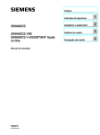
moog
MSD Servo Drive
Description of remark
TWINsync module
moog
MSD Description of remark TWINsync module
L2
L3
L1
NOTE: This document does not replace the MSD Servo Drive Operation
Manual. Please be sure to observe the information contained in the “For
your safety”, “Intended use” and “Responsibility” sections of the Operation
Manual (ID no.: CA65642-001). For information on installation, setup and
commissioning, and details of the warranted technical characteristics of the
MSD Servo Drive series, refer to the additional documentation (Operation
Manual, User Manual, etc.).
x 11
+
-
+
-
+
-
-
+
x
8
x 10
x
9
x
x
7
6
Description of remark
TWINsync module
Interface X
8
ID no.: CB08759-001, Rev. 1.0
Date: 10/2010
Applicable as from firmware version: V2.15 / V201.07
Technical alterations reserved.
The contents of our documentation have been compiled with greatest care and in compliance with our present status of information.
Nevertheless we would like to point out that this document cannot always be updated
parallel to the technical further development of our products.
Information and specifications may be changed at any time. For information on the latest version please refer to [email protected].
Table of contents
5.3
TWINpos mode........................................................................................................14
5.3.1
TWINpos Master mode.................................................................................14
5.3.2 TWINpos Slave mode...................................................................................14
1.
2.
TWINsync technology option.................................................... 4
1.1
Hardware requirements...........................................................................................4
1.2
Software requirements............................................................................................4
6.Monitoring functions / Error messages.................................... 16
Installation................................................................................ 5
2.1Pin assignment of the TWINsync connecting cable..................................................5
3.
Parameter description............................................................... 6
3.1General parameters of the TWINsync communication interface...............................6
3.1.1
Master/Slave selector (P 2614)...........................................................................7
3.1.2
Communication timeout monitoring............................................................7
3.1.3
Structure of the TWINsync data telegram.....................................................7
3.1.4
Configuration of the process data................................................................8
3.1.5
Scaling of process data.................................................................................8
3.1.6
Boot-up delay...............................................................................................9
3.2
Parameterization of the TWINsync master axis.........................................................9
3.3
Parameterization of the TWINsync slave axis............................................................10
4.
Open-loop control via TWINsync..............................................11
5.
TWINsync operation modes.................................................... 12
5.1
USER mode..............................................................................................................12
5.2
TWINspeed mode....................................................................................................12
5.2.1
TWINspeed Master.......................................................................................12
5.2.2 TWINspeed Slave Mode 1.............................................................................13
5.2.3 TWINspeed Slave Mode 2.............................................................................13
moog
MSD Description of remark TWINsync module
3
[ TWINsync module ]
moog
1. TWINsync technology option
MSD Description of remark TWINsync module
4
Key features of the TWINsync option:
–– Serial data transfer via twisted-pair cable (RS485) in master/slave mode
–– Electrical isolation of the transfer channel from the control board
This document describes the TWINsync technology option for the MSD Servo Drive. The
TWINsync technology option is based on an optional communication interface available
for the MSD Servo Drive for option slot 2 via which two MSD Servo Drive devices can be
interconnected at a time. Consequently, use of the TWINsync option is intended for applications in which, for example, synchronism of two drives is specified or in which one
drive is to use I/O or encoder interfaces of another drive.
–– Transfer rate: 4 MBaud
Using the TWINsync option, any process data can be exchanged between two drives.
The data are exchanged bidirectionally with the cycle time of the speed control.
–– Monitored synchronization of master and slave at PWM level
The TWINsync communication interface incorporates a synchronization mechanism.
The MSD Servo Drive configured as the TWINsync master generates a cyclic signal
pulse synchronized to its own control cycle on the SYNC OUT line of the interface. The
MSD Servo Drive configured as the TWINsync slave receives the synchronization signal
on its SYNC IN line and synchronizes its own control cycle to the TWINsync master.
!
ATTENTION: Because of the synchronization mechanism, the EtherCAT and
SERCOS II field bus options are currently not supported in "TWINsync slave"
mode, as they have their own synchronization mechanisms.
Configuration parameters can be set to define the process data to be exchanged via the
TWINsync interface. The parameters from which the data to be sent are compiled, and
the parameters to which the received data are copied, are set both for the TWINsync
master and the TWINsync slave. By way of the TWINsync interface a maximum of three
parameters with a maximum total 8 bytes' length can be cyclically exchanged in both
directions. The following listing summarizes the key features of the TWINsync option.
–– Full-duplex mode
–– Frame size: 12 bytes, of which 8 bytes user data in each transfer direction
–– Frame rate: Data transfer takes place at the speed control clock rate (depending
on the switching frequency, 8 kHz maximum)
–– Free mapping of the sent and received data onto parameters
–– Monitoring of data transfer with a 16-bit CRC checksum
1.1 Hardware requirements
For TWINsync linking of two MSD Servo Drive drives the TWINsync option board for
the X8 technology interface of the MSD Servo Drive is required in both drives (article
no.: G39x-xxx-x4x-xxx). The TWINsync option board is factory-fitted and automatically
detected by the MSD Servo Drive firmware (monitored via display parameter P 0053 =
TWINsync (2)).
1.2 Software requirements
Firmware version V2.15 / V201.07 is required to run the TWINsync option.
2. Installation
!
ATTENTION: Please be sure to read the MSD Servo Drive Operation Manual
before installing the device. It contains essential information relating to safety
and installation as well as detailed connection diagrams.
The TWINsync connecting cable must be shielded. The pin assignment of the D-Sub
male connectors on the cable ends is set out in table 2.2. When using a twisted-pair
connecting cable, the pairs must be formed from the respective matching terminals (+
and -). The signal pairs of SYNC IN and SYNC OUT and of RX and TX must be crossed
over in the cable. The SYNC IN on one connector end is connected to the SYNC OUT on
the other end and vice versa. The same applies to RX and TX. The '+' cable of one signal
must be connected to the respective '+' cable of the other. The respective '-' cables must
be interconnected in the same way.
Connector 1
Cable
Connector 2
Pin no.
2.1 P in assignment of the TWINsync connecting
cable
The TWINsync option board is located on option slot 2 of the MSD Servo Drive (see
Operation Manual) and has a 9-pin D-Sub female connector (X8). The connector pin assignment is set out in table 2.1.
Pin
Option board X8 signal
Meaning
1
SYNC IN-
Synchronization interrupt in via RS485 converter
2
SYNC OUT-
3
GND
GND from driver
4
RX+
UART via RS485 converter Receive +
5
TX+
UART via RS485 converter Transmit +
Synchronization interrupt out via RS485 converter
6
SYNC IN+
7
SYNC OUT+
8
RX-
UART via RS485 converter Receive -
9
TX-
UART via RS485 converter Transmit -
Table 2.1
Table 2.2
Pin no.
1
SYNC IN-
SYNC OUT-
2
2
SYNC OUT-
SYNC IN-
1
3
GND
GND
3
4
RX+
TX+
5
5
TX+
RX+
4
6
SYNC IN+
SYNC OUT+
7
7
SYNC OUT+
SYNC IN+
6
8
RX-
TX-
9
9
TX-
RX-
8
Pin assignment of the TWINsync connecting cable
Synchronization interrupt in via RS485 converter
Synchronization interrupt out via RS485 converter
Assignment of the 9-pin D-Sub female connector X8 on the TWINsync option board
moog
MSD Description of remark TWINsync module
5
[ TWINsync module ]
moog
MSD Description of remark TWINsync module
3. Parameter description
ID
SubID
P 2616
0
The following details the specific parameters of the TWINsync option board.
NOTE: For a description of general parameters refer to the MSD Servo Drive
user documentation.
3.1 G
eneral parameters of the TWINsync
communication interface
Table 3.1 shows the configuration parameters for the communication interface of the
TWINsync option.
ID
SubID
P 2613
0
P 2614
0
Name
TOPT_MASLV_MaxFaultTime
TOPT_MASLV_Mode
Unit
ms
Description
Float32
Select Master or Slave
Mode
UInt16
1 = SLAVE
Table 3.1
TOPT_MASLV_ProcessSendData
TOPT mapping of process
data to be send
UInt16
0
TOPT_MASLV_ProcessSendData
number of mapped process data objects to be send
UInt32
1
TOPT_MASLV_ProcessSendData
1. mapped process data
UInt32
2
TOPT_MASLV_ProcessSendData
2. mapped process data
UInt32
3
TOPT_MASLV_ProcessSendData
3. mapped process data
UInt32
Configuration parameters of the TWINsync technology option board
TOPT mapping of process
data to be send
TOPT_MASLV_ProcessReceiveData
number of mapped process data objects to be
recieved
Data
type
UInt32
1
TOPT_MASLV_ProcessReceiveData
1. mapped process data
UInt32
TOPT_MASLV_ProcessReceiveData
2. mapped process data
UInt32
3
TOPT_MASLV_ProcessReceiveData
3. mapped process data
UInt32
P 2617
0
TOPT_MASLV_Statusword
recieved system statusword
UInt16
P 2618
0
TOPT_MASLV_BootDelay
Increase boot-time to allow
synchronisation
UInt16
Status of communication
UInt16
P 2619
TOPT_MASLV_CommStatus
ms
0 = No error
1 = Communication Error
2 = switching-frequency
discrepancy
3 = mode conflict
4 = remote error
P 2651
TOPT_MASLV_SlaveErrCtrl
Activates the current slave
error monitoring
UInt8
P 2583
TOPT_MASLV_SlaveInvert
Invert slave motion direction
Int8
Table 3.1
2 = MASTER
Description
TOPT_MASLV_ProcessReceiveData
Data
type
Maximum fault state time
for TOPT communication
channel
Unit
2
0 = OFF
P 2615
Name
6
Configuration parameters of the TWINsync technology option board
3.1.1 Master/Slave selector (P 2614)
3.1.2 Communication timeout monitoring
By way of the TWINsync interface the TWINsync slave synchronizes to the TWINsync
master. Consequently, one of the two drives must be configured as the TWINsync master and one as the TWINsync slave. Parameter P 2614 is use to specify the Master/Slave
mode.
ID
Selection
text
Value
P 2614
OFF
0
Selecting OFF disables the TWINsync interface. In the OFF state no
process data are sent and no SYNC OUT signal is generated.
SLAVE
1
Selecting SLAVE switches the MSD Servo Drive to TWINsync Slave
mode. The slave drive synchronizes its control cycle to the incoming
SYNC IN signals. If the SYNC IN signal is not received for a parameterizable time, a communication error is reported (see section
3.1.2 )
MASTER
Table 3.2
!
2
Description
Selecting MASTER switches the MSD Servo Drive to TWINsync
Master mode. SYNC OUT signals are generated for the slave.
P 2614 setting options
ATTENTION: For synchronization it is essential that both drives are configured
to the same switching frequency, as it is used for synchronization. Consequently, parameter P 0302 must be set to the same value for both axes.
moog
A disturbance on the communication interface is detected as follows:
–– The MSD Servo Drive receives invalid data (CRC monitoring).
–– The synchronization signal of the TWINsync master drops out.
If one of these errors occurs, the transfer channel is assumed to be disturbed. Parameter
P 2613 defines the time interval (in ms) over which the channel may be classed as disturbed without an error being reported. In the event of a disturbance the last correctly
received data are frozen. The error messages are documented in section 6.
3.1.3 Structure of the TWINsync data telegram
The TWINsync data telegram is structured as shown in table 3.3. It comprises 3x2 bytes
of fixed data (16 bits CRC, 16 bits TWINsync status word and one control/status word to
change the slave device state) and 6 bytes of freely configurable data.
Checksum
(fixed)
TWINsync
Status word
(fixed)
2 bytes
Table 3.3
2 bytes
Control/
status word
(DRIVECOM)
(fixed)
2 bytes
PDO1
PDO2
PDO3
(configurable)
(configurable)
(configurable)
6 bytes
TWINsync data telegram
MSD Description of remark TWINsync module
7
[ TWINsync module ]
moog
MSD Description of remark TWINsync module
The checksum is formed in each case across the entire telegram. The assignment of the
TWINsync status word is shown in table 3.4.
Bit no.
Function
0
ProcessDataMode
Description
0 = initialization mode
Bit no.
2 bytes parameter ID of the parameter to be sent as HEX value
xxxxSSxxh
1 byte parameter sub-ID of the parameter to be sent as HEX value
SwitchingFrequency
010 = 6 kHz
011 = 8 kHz
100 = 12 kHz
101 = 16 kHz
4-6
TWINMode
16-bit parameters (Int16,UInt16): WW = 10h.
000 = 2 kHz
001 = 4 kHz
0 = TWINsync off
1 bytes word width of the parameter to be sent as HEX value
32-bit parameters (Int32,UInt32, Float32): WW = 20h.
1 = cyclic mode
1-3
Description
PPPPxxxxh
xxxxxxWWh
8
Table 3.5
S tructure of parameter P 2615 / P 2615 (sub-ID: 1-3) for mapping of the process
data to be sent
A fundamental requirement when configuring the process data is that the sequence
and data width of the received data of one axis matches the sequence and data width
of the sent data of the other axis. This parameter matching cannot be monitored by the
MSD Servo Drive and so must be ensured by the user.
1 = TWINsync slave
2 = TWINsync master
7
SlaveInSync
0 = slave is synchronized
1 = slave is not synchronized
8-13
not_used
14
SystemError
Drive in "error" state
15
TechOptError
Communication error occurred
Table 3.4
Reserved
Assignment of the TWINsync status word (parameter P 2617)
3.1.4 Configuration of the process data
The process data to be sent and received by the drive can be configured by parameters.
For manual configuration, parameters P 2615 (mapping of sent data) and P 2616 (mapping of received data) can be modified directly. The mode selector (parameter P 2580)
can also be used to set an automatic configuration for preset operation modes (see
section 5). P 2615 and P 2616 are field parameters with four elements each. The first
element (sub-ID: 0) determines how many parameters are sent/received by this axis. A
maximum of three parameters are supported in each direction. The other three field elements (sub-ID:1-3) select which parameters are sent/received. The entries under sub-ID
1-3 are coded as set out in table 3.5.
3.1.5 Scaling of process data
In order to transfer the three most frequently used variables – torque, speed and position – via the TWINsync interface simultaneously, appropriate conversion of torque and
speed variables from the internally used 4-byte floating-point format into a scaled 2-byte
integer format is implemented. The reference variables for scaling of the "local" torque
and speed values (sent data) are preset via parameter P 2602. The reference variables for
de-scaling of the ("remote") torque and speed values received from the external drive
are preset via parameter P 2609 (see table 3.6).
The first field entry (sub-ID:0) of P 2602 / P 2609 contains the value of the reference
torque in Nm. The second field entry (sub-ID:1) contains the value of the reference speed
in rpm. The scaling maps the value range between the negative and positive reference
values to the number range [-32768 to 32767]. The position data are transferred in the
format specified by the unit parameter setting of the device (Factor Group) as 32-bit
integer.
NOTE: Generally, the reference variables P 2602 / P 2609 and the factor group
settings should be identical in the master and slave drives.
ID
SubID
Name
P 2602
Unit
Description
Data
type
MPRO_TWIN_LocalScaling
0
MPRO_TWIN_LocalScalingTorque
Nm
Local drive reference
torque
Float32
1
MPRO_TWIN_LocalScalingSpeed
rpm
Local drive reference
speed
Float32
P 2609
ID
SubID
Name
Unit
P 2603
0
MPRO_TWIN_RemoteRefTorque
Scaled
Scaled torque reference
(remote)
Int16
P 2604
0
MPRO_TWIN_RemoteActTorque
Scaled
Scaled actual torque
(remote)
Int16
P 2605
0
MPRO_TWIN_RemoteRefSpeed
Scaled
Scaled speed reference
(remote)
Int16
P 2606
0
MPRO_TWIN_RemoteActSpeed
Scaled
Scaled actual speed
(remote)
Int16
P 2607
0
MPRO_TWIN_RemoteRefPos
POS
Position reference
(remote)
Int32
P 2608
0
MPRO_TWIN_RemoteActPos
POS
Actual position (remote)
Int32
MPRO_TWIN_RemoteScaling
0
MPRO_TWIN_RemoteScalingTorque
Nm
External drive reference
torque
Float32
1
MPRO_TWIN_RemoteScalingSpeed
rpm
External drive reference
speed
Float32
Table 3.6
Reference variables for scaling of the local and external torque and speed signals
Table 3.7 shows the parameters typically used for the process data being sent. Parameters P 2596 to P 2601 describe the "local" target and actual values for torque, speed
and position.
ID
SubID
P 2596
0
MPRO_TWIN_LocalRefTorque
Scaled
Scaled torque reference
(local)
Int16
P 2597
0
MPRO_TWIN_LocalActTorque
Scaled
Scaled actual torque
(local)
Int16
P 2598
0
MPRO_TWIN_LocalRefSpeed
Scaled
Scaled speed reference
(local)
Int16
P 2599
0
MPRO_TWIN_LocalActSpeed
Scaled
Scaled actual speed
(local)
Int16
P 2600
0
MPRO_TWIN_LocalRefPos
POS
Position reference (local)
Int32
P 2601
0
MPRO_TWIN_LocalActPos
POS
Actual position (local)
Int32
Table 3.7
Name
Unit
Description
Data
type
Parameters frequently used to send process data
Table 3.8 shows the parameters typically used for the process data being received.
Parameters P 2603 to P 2608 are available as data containers to receive the external
("Remote") target and actual values for torque, speed and position.
moog
Table 3.8
Description
Data
type
Parameters frequently used to receive process data
The scaled parameters for speed and torque provided on the send end also exist on
the receive end. The torque and speed information required for de-scaling is entered in
parameter P 2609. As a result the received 16-bit integer is converted back to the local
units system.
3.1.6 Boot-up delay
The synchronization between the master and slave axes takes a certain amount of time
after booting up. If one or both of the controllers in the TWINsync pairing is set to
control mode without a delay after connection of the power, it may be that a communication error is reported because no synchronization has yet taken place. This can be
prevented by using parameter P 2618 (see table 3.1) to extend the boot-up initialization
phase of the MSD Servo Drive by a programmable time so that the synchronization is
completed during initialization.
3.2 Parameterization of the TWINsync master axis
The master axis receives reference (setpoint) values according to the parameterized
reference source (e.g. from a field bus). Apart from configuration of the send data, the
master axis requires no further special parameter setting. Slave process data can also be
received however.
MSD Description of remark TWINsync module
9
[ TWINsync module ]
moog
3.3 Parameterization of the TWINsync slave axis
The slave axis receives the reference (setpoint) values from the master axis and uses
them dependent on the TWINsync mode preset via parameter P 2580. Depending on
the mode, master axis torque, speed or position reference or actual values are required.
For the slave axis to receive the reference value via the TWINsync interface, the setpoint source must be configured via parameter P 0165 ("MPRO_REF_SEL") to the value
11=TWINsync. The reference values for control of the slave axis are then formed from
the parameters listed in table 3.8 dependent on the control mode set by the control
mode selector (P 0300). The scaled parameters are first scaled back to the local units
system in line with field parameter P 2609.
MSD Description of remark TWINsync module
10
4. Open-loop control via TWINsync
The slave drive in the TWINsync pairing can be controlled by the TWINsync master by
way of the TWINsync control word or any other control location (e.g. digital inputs or
field bus). The control location is configured using the control location selector (parameter: P 0159). To select the control location "TWINsync", the value "TWINsync (8)" must
be set for P 0159. Open-loop control of the drive is then effected by way of the TWINsync control word (parameter P 2611, see table 4.1 ) and the drive status is mapped in
parameter P 2612 (see table 4.2 ). The TWINsync master copies its own control word to
the TWINsync control word transferred over the process data channel from the TWINsync master to the TWINsync slave. The TWINsync slave thus obeys the same control
commands as the TWINsync master. Error resets and homing can additionally be initiated on the slave by way of the TWINsync control word. The TWINsync slave likewise
transfers its TWINsync status word back to the TWINsync master via the process data
channel.
Bit no.
Function
Description
Reserved
Bit no.
Function
Description
14
FREE3
Reserved
15
FREE4
Reserved
Table 4.1
Assignment of the TWINsync control word (parameter P 2611)
Bit no.
Function
Description
0
Operation_mode_0
1
Operation_mode_1
2
Operation_mode_2
3
Operation_mode_3
4
Operation_mode_4
Reserved
5
OperationEnabled
Loop control active
6
Fault
Drive in fault (error) state
7
CoastStop
Drive is torque-free
8
QuickStop
Drive in "quick-stop" state
9
Homing attained
Drive is homed
0
Operation_mode_0
10
FREE1
1
Operation_mode_1
11
FREE2
2
Operation_mode_2
12
FREE3
3
Operation_mode_3
13
ActDrivecom_0
Current DriveCom state bit 0
4
Operation_mode_4
14
ActDrivecom_1
Current DriveCom state bit 1
5
EnableOperation
Start loop control
15
ActDrivecom_2
Current DriveCom state bit 2
6
SwitchOn
Switch on power stage
7
CoastStop
Drive torque-free
8
QuickStop
Quick stop
9
StartHoming
Start homing
10
FaultReset
Fault (error) reset
11
EnableVoltage
#
12
FREE1
Reserved
13
FREE2
Reserved
Table 4.1
Table 4.2
Reserved
Assignment of the TWINsync control word (parameter P 2612)
Assignment of the TWINsync control word (parameter P 2611)
moog
MSD Description of remark TWINsync module
11
[ TWINsync module ]
moog
5. TWINsync operation modes
By way of parameter P 2580 various preset TWINsync operation modes can be selected.
The process data configuration is automatically effected according to the selected mode.
In the following the selectable operation modes are listed.
MSD Description of remark TWINsync module
5.2 TWINspeed mode
TWINspeed mode is useful for speed synchronization of mechanically coupled axes, such
as twin traction or lift drives. The master transfers its actual speed and torque values via
the TWINsync interface to the TWINsync slave. The TWINsync slave then processes the
two variables and forwards them to an internal closed-loop control structure. Figure 5.1
shows the process data interface between the master and slave drives in TWINspeed
mode.
5.1 USER mode
If this mode is selected the user can assign the process data channel of the TWINsync
bus freely. For this, field parameters "TOPT_TWIN_ProcessSendData" (P 2615) and
"TOPT_TWIN_ProcessReceiveData" (P 2616) can be used to define how many, and
which, objects are to be sent or received (see section 3.1.4).
If the mapping (parameter TOPT_TWIN_ProcessSendData (P 2615) / TOPT_TWIN_RecieveData (P 2616)) is changed by the user, the mode is automatically reset to USER.
12
Fixed mapping
Control word P2611
Communication status P2617
Checksum
Status word P2612
Communication status P2617
Checksum
MSD
Servo Drive
Master
Mapping by mode TWINSPD
MSD
Servo Drive
Slave
Actual torque P2597
Actual speed P2599
Error number P2650[0]
Error location P2650[1]
Figure 5.1 TWINspeed process data interface
5.2.1 TWINspeed Master
This mode is selected by setting P 2580 = "TWINSPD_Master". In this mode the master transmits its actual torque (P 2597) and actual speed (P 2599) values. The received
data expected by the master via TWINsync are interpreted as the current error number
(P 2650[0]) and error location (P 2650[1]) of the slave drive.
5.2.2TWINspeed Slave Mode 1
ID
In this mode the actual speed value of the master drive is used as the primary speed
reference (primary setpoint) of the slave drive. A secondary reference proportional to
the primary reference is added to the primary reference and specified as a percentage by way of parameter P 2584. If the secondary reference calculated in this way falls
below the threshold value set by parameter (P 2585), that threshold value is used as the
secondary reference. In this, the sign of the secondary reference corresponds to the sign
of the actual torque value of the master drive. Figure 5.2 shows the closed-loop control
structure of the slave drive.
Master
actual torque
P2597
P2609[0]
32768
P2584
Master
actual speed
P2599
P2609[1]
32768
Setting in master
Setting in slave
MASTER (2)
SLAVE (1)
TWIN_Setting
TWINSPD_MASTER1 (1)
TWINSPD_SLAVE1 (2)
Control mode
Any
SCON(2)
P 0165
Reference selector
Any
TWINsync (11)
P 0301
Reference mode
P 2615
Mapping of send
data
TWINdrive mode
P 2580
P 0300
P2581
P2585
x
SIGN()
MAX()
x
Slave
torque setpoint
P2582
P 2616
Filter
–
Speed
controller
Slave
actual speed
Parameter
P 2614
Torque setpoint Torque setpoint
filter
limitation
Any
moog
Table 5.1
Meaning
Parameter value
Meaning
Sub-ID 0
0x0000 0002
2 objects
0x0000 0002
2 objects
Sub-ID 1
0x0A25 0010
Actual torque
P 2597[0]
(16 bits)
0x0A5A 0010
Current error number
P 2650[0]
(16 bits)
Sub-ID 2
0x0A27 0010
Actual speed
P 2599[0]
(16 bits)
0x0A5A 0110
Current error location P 2650[1]
(16 bits)
Parameter value
Meaning
Parameter value
Meaning
Mapping of receive
data
Sub-ID 0
0x0000 0002
2 objects
0x0000 0002
2 objects
Sub-ID 1
0x0A5A 0010
Current error number
P 2650[0]
(16 bits)
0x0A2C 0010
RemoteActTorque P 2604[0]
Sub-ID 2
0x0A5A 0110
Current error location P 2650[1]
(16 bits)
0x0A2E 0010
RemoteActSpeed
P 2606[0]
Figure 5.2 Closed-loop control structure, TWINspeed Slave Mode 1
The actual torque value of the master determines the torque reference limitation in the
slave drive. Accordingly, during a positioning job the torque limitation of the slave is
adapted online to the actual torque value of the master. The torque is thus split optimally across both drives and pass-through of the slave drive is prevented in the event of
short-time cutting of the mechanical coupling, such as when mechanical slip occurs in a
traction drive.
IP mode (1)
Parameter value
P arameters on master and slave drive for the preset TWINsync mode TWINspeed
Mode 1
5.2.3TWINspeed Slave Mode 2
This mode is a further variant for synchronization of mechanically coupled drive axes.
The master transfers its current actual speed and torque values via the TWINsync
interface to the slave. The slave uses the current master actual torque value as a torque
pre-control signal on the speed controller output. The received actual speed value of the
master is used as the speed reference for the slave's speed control loop. Optionally, the
actual speed value can be filtered via a PT-1 element. The speed controller on the slave
side should be configured as a weak P-controller in this mode.
MSD Description of remark TWINsync module
13
[ TWINsync module ]
moog
Mapping of the process data channel on the master and slave sides is the same as in
TWINspeed Mode 1 (see table 5.1).
5.3 TWINpos mode
This mode is useful for position synchronization between a master and slave drive. An
electronic gear unit can additional be used on the slave axis. Figure 5.3 shows the process data interface between the master and slave drives in TWINpos mode.
5.3.2TWINpos Slave mode
In this mode the actual position value of the master drive (P 2608) is used for positioning
reference generation and the current actual speed value (P 2606) for external speed precontrol generation. Figure 5.4 shows the logical sequencing.
P270 Slave internal resolution
[incr/rev]
P2652 Master_internal resolution
[incr/rev]
1/P2657
MPRO_TWIN_StrechFactor
Master actual position
(k-1) [incr]
P2608
Master actual position (k)
[incr]
-
Fixed mapping
∆ Position
[incr]
x
P2583
Position setpoint
SlaveModuloValue
[Userunits]
[incr]
∆ Position_corr
[incr]
Control word P2611
Communication status P2617
Checksum
MSD
Servo Drive
Master
14
MSD Description of remark TWINsync module
x
POS 2
USER
x
x
Status word P2612
Communication status P2617
Checksum
Mapping by mode TWINPOS
+
MSD
Servo Drive
Slave
Actual position P412
Actual speed P2599
Analog input xx
[-1 ... 1]
P2583
Slave inversion
[-1/1] Correction_factor_
Nref_FF
P2606
Master actual speed
[U/min]
x
+
x
x
x
Speed pre-control value
[Userunits]
1/P2657
MPRO_TWIN_StrechFactor
Figure 5.3 TWINpos process data interface
Correction factor Nref FF =
This mode is selected by setting P 2580 = "TWINPOS_Master". In this mode the master
transmits its actual position (P 0412) and speed (P 2599) values. The received data are
interpreted as the current error number (P 2650[0]) and error location (P 2650[1]) of the
slave drive.
x
P2655
Correction factor
Error number P2650[0]
Error location P2650[1]
5.3.1 TWINpos Master mode
P2653
MPRO_TWIN_
ElecGearNum
P2654
MPRO_TWIN_
ElecGearDen
Slave internal resolution [Userunits/rev] * IpRefTS [ms]
60000 [min * s/min * s/ms]
Figure 5.4 TWINpos Slave closed-loop control structure
Delta increments per scan step are formed from the incremental master actual position
P 2608. If the resolution factors vary between the master and slave, the delta increments
are corrected by the factor P 0270 / P 2652. Then the corrected delta increments are
multiplied firstly by the transmission ratio of the electronic gearing (P 2653 / P 2654) and
secondly by the analog correction factor and the results are added together. In addition,
parameter P 2583 can be used to execute a reversal of rotation direction between the
master and slave. Then the corrected delta increments are up-integrated to the incremental modulo value of the slave. For external speed pre-control, the current actual
speed value of the master is used in revolutions per minute. Just as in position process-
ing, this actual value is multiplied by the factor of the electronic gearing (P 0270 / P 2652)
and by the same analog correction factor.
ID
Parameter
P 2614
TWINdrive mode
P 2580
Setting in master
Setting in slave
MASTER (2)
SLAVE (1)
TWIN_Setting
TWINPOS_MASTER (7)
TWINPOS_SLAVE (8)
P 0300
Control mode
Any
PCON(2)
P 0165
Reference selector
Any
TWINsync (11)
P 0301
Reference mode
Any
IP mode (1)
P 2615
Mapping of send
data
P 2616
Table 5.2
Parameter value
Meaning
Parameter value
Meaning
Sub-ID 0
0x0000 0002
2 objects
0x0000 0002
2 objects
Sub-ID 1
0x019C 0010
Actual position
P 0412 (32 bits)
0x0A5A 0010
Current error number
P 2650[0]
(16 bits)
Sub-ID 2
0x0A27 0010
Actual speed
P 2599[0]
(16 bits)
0x0A5A 0110
Current error location P 2650[1]
(16 bits)
Parameter value
Meaning
Parameter value
Meaning
Mapping of receive
data
Sub-ID 0
0x0000 0002
2 objects
0x0000 0002
2 objects
Sub-ID 1
0x0A5A 0010
Current error number
P 2650[0]
(16 bits)
0x0A30 0020
RemoteActPos
P 2608[0]
Sub-ID 2
0x0A5A 0110
Current error location P 2650[1]
(16 bits)
0x0A2D 0010
RemoteRefSpeed
P 2605[0]
Parameters on master and slave drive for the preset TWINsync mode TWINpos
moog
MSD Description of remark TWINsync module
15
[ TWINsync module ]
moog
MSD Description of remark TWINsync module
6. M
onitoring functions /
Error messages
The data transfer of the master/slave link is continuously monitored. Errors can occur either when a parameter is incorrectly set or if there is a disturbance on the transfer channel. Errors are only reported when the MSD Servo Drive is in closed-loop control mode
(display shows state 5). The master/slave link has the primary error group (error number)
46. A list of possible errors is set out in table 6.1.
Error ID
46
00
Error cause
Remedy
Faulty data transfer. This can occur when
there has been disturbance on the channel
for a time longer than that configurable via
P 02613. The error is also reported if the
slave has lost the synchronization.
Check connector.
Check cable.
Check MSD Servo Drive.
46
01
Master and slave have different switching
frequency parameter settings.
Correct parameter setting.
46
02
Both axes are parameterized either as
master or as slave.
Correct parameter setting.
Table 6.1
Error messages in master/slave operation
16
TAKE A CLOSER LOOK.
Moog solutions are only a click away. Visit our worldwide Web site for more information
and the Moog facility nearest you.
moog
Moog GmbH
Hanns-Klemm-Straße 28
D-71034 Böblingen
Telefon +49 7031 622 0
Telefax +49 7031 622 100
www.moog.com/industrial
[email protected]
Moog is a registered trademark of Moog, Inc. and its subsidiaries.
All quoted trademarks are property of Moog, Inc. and its subsidiaries.
All rights reserved.
© 2010 Moog GmbH
Technical alterations reserved.
The contents of our documentation have been compiled with
greatest care and in compliance with our present status of information.
Nevertheless we would like to point that this document cannot
always be updated parallel to the technical further development
of our products.
Information and specifications may be changed at any time. For
information on the latest version please refer to
[email protected].
ID no: CB08759-001 Rev. 1.0, 10/2010