1
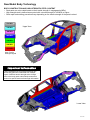
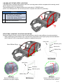
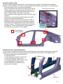
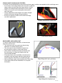
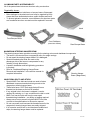
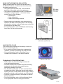
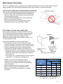
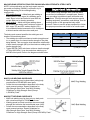
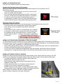
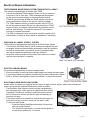
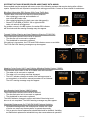
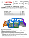
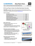
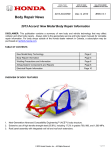
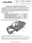
MODEL/YEAR MODÈLE /ANNÉE DATE OF ISSUE DATE EN VIGUEUR BULLETIN NUMBER NUMÉRO DU BULLETIN 2015 TLX AUG. 22, 2014 BRN-14-9 Body Repair News 2015 TLX: New Model Body Repair Information DISCLAIMER: This publication contains a summary of new body and vehicle technology that may affect collision and other body repairs. Always refer to the appropriate service and body repair manuals for complete repair information. A subscription may be purchased at: techinfo.acura.com TABLE OF CONTENTS New Model Body Technology Page 2 Body Repair Information Page 8 Welding Precautions and Information Page 9 Airbag System Components and Repairs Page 11 Electrical Repair Information Page 13 OVERVIEW OF BODY FEATURES 2 4 5 3 1 1. 2. 3. 4. 5. Next-Generation Advanced Compatibility Engineering™ (ACE™) body structure. Body construction using 56% high tensile strength steel, including 10% in grades 780, 980, and 1,500 MPa. Reinforced cabin with 1,500 MPa one-piece front door outer stiffener rings. Rigid magnesium steering hanger beam mounts steering column and dashboard components. First Acura use of NVH acoustic spray foam, replacing baked-in acoustic separators. © 2014 Honda Canada., Inc. – All Rights Reserved 1 of 16 New Model Body Technology BODY CONSTRUCTION AND HIGH STRENGTH STEEL CONTENT • Steel parts are color-coded based on their tensile strength in megapascals (MPa). • High strength steel is defined as any steel with a tensile strength of 340 MPa or higher. • Steel repair and welding procedures vary depending on the tensile strength of the parts involved. 270 MPa Upper View 340 MPa 440 MPa 590 MPa 780 MPa 980 MPa 1,500 MPa Steel Tensile Strength Legend Important Information These illustrations are for general reference only. Some body parts are constructed from multiple layers of different tensile strength steels. Always refer to the body repair manual body construction section for specific steel tensile strength information. Lower View 2 of 16 1,500 MPa (HOT STAMP) STEEL LOCATIONS 1,500 MPa steel is stronger than ordinary steel, so it can help protect vehicle occupants while reducing overall vehicle weight to improve fuel efficiency. The numbered parts in the diagrams below are constructed of 1,500 MPa steel: (NOTE: The bulleted parts are only serviced as part of the complete outer stiffener ring assembly) All Models 1 2 Outer Stiffener Ring (including): • Side Sill Center Stiffener • Center Pillar Lower Reinforcement • Center Pillar Reinforcement 2 Inside Sill Reinforcement 1 STRUCTURAL ADHESIVE LOCATIONS AND REPAIR Structural adhesive (foam) is used to improve body stiffness under the outer stiffener ring as shown below. • When replacing the outer stiffener ring, a special room-temperature cured 2-part epoxy structural adhesive (L&L Products L-0504 or equivalent) is required to replicate these joints. Outer Panel Adhesive (green) Outer Stiffener Rings Side Sill Ext. Z Stiffener Ring Y SECTION B-B A Outer Panel B Bulkhead Adhesive (green) A Stiffener Ring DETAIL Z: DETAIL Y: Between outer stiffener ring & bulkhead of front pillar complete B SECTION A-A Between outer stiffener ring & side sill reinforcement rear extension 3 of 16 ACOUSTIC SPRAY FOAM To improve body sealing and reduce NVH, acoustic spray foam is applied. This replaces the traditional baked-in acoustic separators. The foam is factory applied after paint and quickly cures at room temperature. • Service procedure is the same as factory application. Refer to the Replacement section of the body repair manual. C-Pillar Upper Shelf (Red) • If foam replacement is required during body repairs, use a commercially available 2-part polyurethane foam, such as 3M AUTO MIX Flexible Foam 8463, or equivalent. • Foam is applied through designated holes in the vehicle body structure. • Plastic foam control shelves installed inside body cavities control foam travel during application. • Replacement shelves are part of the steel parts COMP, or available as separate service parts, depending on location. • The minimum foam application amount for each location is Foam Mass provided in grams. To determine applied mass, weigh foam More Than containers on a metric scale before and after application. 60 Grams The difference is the amount of foam applied. Foam Control Shelf Example Acoustic Spray Foam Locations NVH SEALER TAPE AND SEPARATORS To reduce NVH in areas where acoustic foam is not feasible, NVH sealer tape and separators are applied in certain locations between the outer body panel and outer stiffener ring as shown in the diagram below. • The factory applied tape expands during the E-coat bake process. Outer Stiffener Ring Tape • If sealer tape and/or separator replacement is required during body repairs, use a Separator commercially available urethane body sealer. • A specialized NVH damping material, such as 3M #04274, or equivalent, may also be used, if available. Tape Tape Outer Panel 4 of 16 TRUNK HINGE CUSHION AND STOPPER To prevent over-stroke damage to the trunk lid and outer panel, cushions are applied to both trunk hinge arms. • In the event a trunk hinge needs to be removed or replaced, always make sure that either the hinge cushion or hinge stopper are installed before allowing the trunk to open. • Failure to do so will result in damage to the trunk lid and outer panel. • Service replacement trunk hinges come with a stopper installed to prevent damage during installation. • Be sure to install the cushion on the new trunk hinge arm after replacement. Possible Over-Stroke Contact Area Trunk Hinge Cushion Service Hinge w/Stopper REAR WHEEL ARCH HEM JOINT To improve styling and tire clearance, a hemmed rear wheel arch joint is used. • The outer and inner rear panels are joined using adhesive in the wheel opening area. • The outer panel is then rolled and crimped over the inner panel, similar to a door panel crimp. • Other vehicle manufacturers have previously used this technology, so rolling and flanging tools are commercially available. • If the above tools are not available, instructions are provided in the body repair manual to make the set of hemming pliers necessary to complete this joint. • Refer to the body repair manual section titled “Rear Side Outer Panel Removal and Installation” for complete information. 5 of 16 ALUMINUM PARTS & REPAIRABILITY All of the parts shown below use aluminum alloy construction. Repairability Issues: • Do not repair the front subframe or bumper beams if damaged. • Minor damage to the aluminum hood may be repaired by body shops that have dedicated aluminum repair facilities and tools. • To prevent galvanic corrosion, some fasteners for aluminum parts are considered one-time use and must be replaced if removed. Hood Front Bumper Beam Front Subframe (Aluminum & Steel) Rear Bumper Beam MAGNESIUM STEERING HANGER BEAM The steering hanger beam provides mounting for the steering column and dashboard components. • The beam is constructed from a magnesium alloy for weight savings. • Do not repair the steering hanger beam if it is damaged. • Special threaded collar bolts are used on the passenger side of the beam to compensate for any variation in body dimensions. • A specific installation and bolt tightening procedure is required. • Refer to “Dashboard/Steering Hanger Beam Removal and Installation” in the service manual for complete information. Steering Hanger Beam (Magnesium) MAG-FORM® BOLTS AND STUDS • Special MAG-Form bolts and studs are used to fasten dashboard components and electrical grounds to the magnesium steering hanger beam. • These bolts have a 105° flank angle that self-forms threads into the beam as the bolt is installed. • If any original hole in the beam is stripped, it can be repaired by ordering a +1 mm oversize service bolt or stud. • MAG-Form service bolts will form the new repair threads during installation – no drilling or tapping required. • Always use a torque wrench to tighten MAG-Form bolts or studs to the specifications in the service manual. • Do not use power tools because the threads formed in the magnesium steering hanger beam are easily stripped. • If an oversize service bolt or stud has been installed and strips, the steering hanger beam must be replaced. 6 of 16 BLIND SPOT INFORMATION (BSI) SYSTEM Models equipped with this system can be identified by this BSI Alert Indicator, located on both front doors near the outside rearview mirror. • The system uses two radar units, one mounted on each side of the vehicle under the rear bumper. • The system may malfunction and set DTCs because of damage, improper repairs, or excessive foreign material on any of the following: − Rear bumper − Outer side panels − Radar unit mounting locations • • Several checks and inspections must be done during repairs to the radar unit mounting area. If the mounting area check is not done, an Acura dealer may not be able to properly aim the radar units. For more information, refer to “BSI Radar Unit Mounting Area Check” in the service manual. LH BSI Unit Mounting Area Check (RH Side is symmetrical) CAPLESS FUEL FILLER This vehicle uses a capless fuel filler design. It does not have a conventional gas cap. • If you need to refuel the vehicle from a portable fuel container, a funnel is provided in the trunk tool case. • For more information, refer to “Refueling From a Portable Fuel Container” in the owner’s manual. Capless Fuel Filler TOWING AND LIFTING PRECAUTIONS • FWD models may be towed using front wheel lift or flat bed towing equipment. • SH-AWD models must be towed using flat bed towing equipment only, otherwise drive system and/or transmission damage may result. • The SH-AWD system does not have a manual switch to disable the system. Whenever service work requires spinning the front or rear wheels with the engine, always support the vehicle so all four wheels are off the ground. • Do not lift or tow this vehicle by its bumpers, or serious damage will result. • For more information, refer to “Lift and Support Points” in the appropriate service or body repair manual. 7 of 16 Body Repair Information NOTE: The following content is intended only to highlight new/special concerns. No body repairs should be attempted without first referencing the appropriate body repair manual for complete information. USE OF HEAT DURING BODY STRAIGHTENING AND REPAIR When you are doing body straightening and repair procedures: • DO NOT apply heat to any body part during straightening. This may compromise the internal structure and strength of high-strength steel parts. • Any part that has heat applied to it during straightening MUST be replaced with new parts. • Ignoring these instructions may significantly reduce occupant protection in any subsequent collision. SECTIONING (CUT AND JOINT) GUIDELINES Various high-strength steel materials with different sheet thicknesses and strengths are applied in many places that vary by body design in order to increase collision safety performance, body stiffness, and weight reduction. Stiffening members inside each part (patch, stiffener, etc.) are also specified in detail. Follow these guidelines to avoid an unsafe repair: • Sectioning (cut and joint) should usually be avoided except for mild steel outer panels and floor panels unless a specific procedure is provided in the body repair manual. • However, depending on the type of vehicle damage, steel parts with a tensile strength ≤ 780 MPa may be sectioned provided ALL of the following conditions are met: – Sectioning must be done in a single-layer area of the part. – Multi-layer internal steel reinforcements and stiffeners must not be cut. – The repair is not in a load bearing area such as engine, transmission, or suspension mounting points. • • • Replace body structural components such as stiffeners, reinforcements, and other multi-layered steel parts as assemblies that match the replacement parts configuration. Approved welding methods are listed in the table. Refer to the body repair manual section “Parts Sectioning (Cut and Joint) Guidelines” for complete information. Sectioning Area Examples Welding Method Steel Part Tensile Strength (MPa) Spot Weld Plug Butt <590 590 780 980 X 1500 X X MAG Welding Welding Methods For Steel Parts ( = Approved X = Not Approved) 8 of 16 Welding Precautions and Information REPAIRING 1,500 MPa STEEL PARTS Observe these precautions when repairing 1,500 MPa steel parts: • NEVER attempt to straighten damaged 1,500 MPa steel parts because they may crack. • 1,500 MPa steel parts MUST be replaced at factory seams using squeeze-type resistance spot welding (STRSW). DO NOT SECTION these parts! • MIG brazed joints should be used ONLY in locations not accessible by a spot welder. • To assure adequate weld tensile strength, always set the spot welder to the specifications provided in the body repair manual. Important Information Parts made of Ultra High Strength Steel (UHSS/1,500MPa/USIBOR) must be installed as a complete part. No sectioning allowed. Ultra High Strength Steel requires special welding equipment, procedures, and settings. See the welding section of the appropriate body repair manual. Failure to use the proper equipment or follow the proper procedures can result in an unsafe repair. • • • NEVER perform MAG welding on 1,500 MPa steel. The heat generated during MAG welding will significantly reduce the strength and structural integrity of 1,500 MPa steel parts. This photo shows tensile strength test results of MAG welded 1,500 MPa steel. The 1,500 MPa steel fractured first, because the welding heat reduced its strength to far below 590 MPa. For more information, refer to “Repair Guidelines for High-Strength Steel Parts” in the body repair manual. 590 MPa 1,500 MPa MIG BRAZING GUIDELINES FOR 1,500 MPa STEEL PARTS Refer to the body repair manual for complete information: • MIG brazed joint locations are specified in the body repair manual. • A single- or double-hole MIG braze may be specified in the body repair manual depending on the tensile strength of the parts being joined. • The size and number of holes are critical to achieving adequate joint strength. • A pulsed MIG welder MUST be used. Refer to the equipment manufacturer’s instructions for welder voltage and current setup. • The photos at right show the difference in results between pulsed and non-pulsed MIG brazing. 9 of 16 MAG WELDING SPECIFICATIONS FOR 590-980 MPa HIGH-STRENGTH STEEL PARTS NOTE: In this publication and the body repair manuals, gas metal arc welding (GMAW) is referred to by its Important Information subtypes depending on the welding/brazing requirements: Parts made of High Strength Steel (590-980 MPa) • MIG welding/brazing = Metal inert gas welding or must often be installed as a complete part. Section brazing where 100% argon (Ar) shielding gas is only according to published repair information and used. Argon is inert and does not react with the guidelines. This high-strength steel requires special molten weld pool or brazing operation. welding equipment, procedures, and settings. See the • MAG welding = Metal active gas welding where welding section of the appropriate body repair the shielding gas being used contains a mixture of manual. Failure to use the proper equipment or follow 80% argon (Ar) and 20% carbon dioxide (CO2). the proper procedures can result in an unsafe repair. It is considered active because the CO2 undergoes a limited reaction with the molten weld pool. The body repair manual specifies the weld types and locations for each body panel: • The welding wire used must have a tensile strength equal to, or greater than, the lowest tensile strength of the parts being welded. This conversion chart shows the relationship of steel tensile strength (MPa) to the minimum welding wire tensile strength (ksi). • Typical ER70S-6 MIG wire has a minimum tensile strength of 70 ksi (483 MPa). It can be used when welding up to 440 MPa steel parts. Refer to the diagrams shown below: Steel Tensile (MPa) Wire Tensile (ksi) 590 ≥86 780 ≥113 980 ≥142 (1,000 psi = 1 ksi) MAG PLUG WELDING GUIDELINES • MAG plug welding may be done when joining body components to 590-980 MPa steel parts. • Follow the recommendations described in the body repair manual sections “Repair Guidelines for High-Strength Steel Parts” and “MAG Welding Conditions for High-Strength Steel (Except 1,500 MPa) Parts.” MAG BUTT WELDING GUIDELINES • MAG butt welding may be done only on steel parts with a tensile strength of 780 MPa and lower. • Welding speed is critical to achieve the correct weld strength and minimize the heat affected zone (HAZ). • Follow the recommendations described in the body repair manual sections “Repair Guidelines for High-Strength Steel Parts” and “MAG Welding Conditions for High-Strength Steel (Except 1500 MPa) Parts.” 10 of 16 Airbag System Components and Repairs AIRBAG SYSTEM COMPONENTS The airbag system in this vehicle includes the following components that may deploy in a collision: 1. Driver’s and front passenger’s seat belt tensioners (may deploy independently from any airbags). 2. Driver’s and front passenger’s SRS airbags. 3. Driver’s knee SRS airbag. 4. Side airbags mounted in the driver and front passenger outer seat-backs. 5. Left- and right-side curtain airbags mounted above the side windows under the headliner. SMARTVENT™ SIDE AIRBAGS This vehicle is equipped with SmartVent side airbag construction: • This airbag design helps mitigate the risk of excessive airbag deployment force and risk of injury to smaller front passenger seat occupants. • Eliminates the need for the Occupant Position Detection System (OPDS) sensor located in the front passenger’s seatback. As with all side airbags, the following service precautions apply: • Special seat covers and/or breakaway thread are used to ensure proper deployment path. • Damaged front seat covers should be replaced, not repaired. • Do not install non-factory seat covers, because they may alter the airbag's intended deployment path. DRIVER’S KNEE AIRBAG The driver’s knee SRS airbag helps keep the driver in the proper position and to help maximize the benefit provided by the vehicle’s other safety features. • The driver’s knee SRS airbag is mounted to the steering hanger beam below the steering column. • It is designed to inflate in a moderate to severe frontal collision. • Normally, it inflates with the driver’s front airbag, but may also inflate alone under certain conditions. 11 of 16 AIRBAG SYSTEM INDICATORS There are two indicators used for the airbag system: Supplemental Restraint System (SRS) Indicator When you turn the vehicle to the ON mode, this indicator should come on and then turn off after about 6 seconds. • If the SRS indicator does not go off, or does not come on at all, there is a problem with the system. • DTCs must be read and cleared using the HDS (or equivalent) scan tool. Contact an Acura dealer for assistance, if necessary. • If a vehicle is sent to the dealer for airbag system repair or troubleshooting, include a copy of the repair estimate with part numbers and the source for any replaced airbag system parts. Passenger Airbag OFF Indicator The indicator comes on to alert you that the passenger’s front airbag has been turned off. • This occurs when the front passenger’s weight sensors detect 65 lb. (29 kg) or less, the weight of an infant or small child, on the seat. • If the indicator comes on with no front passenger and no objects on the seat, or with an adult occupying the seat, something may be interfering with the seat weight sensors, or there may be a problem with the system. Contact an Acura dealer for assistance, if necessary. Passenger Airbag OFF Indicator KC image to be added AIRBAG SYSTEM REPAIRS REQUIRED AFTER DEPLOYMENT To restore proper function and allow DTCs to be cleared, the airbag system MUST be repaired as specified in the service manual. Refer to “Component Replacement/Inspection After Deployment” for complete information. • DO NOT install used, refurbished, or modified airbag system parts! • When making airbag system repairs, only use new genuine replacement parts, which are manufactured to the same standards and quality as the original parts. • To ensure the correct replacement airbag system parts are installed, provide the vehicle’s VIN when ordering parts. Compare the part numbers on the new and removed parts to make sure they match. AIRBAG SYSTEM ELECTRICAL REPAIRS Except when doing electrical inspections that require battery power, always place the vehicle in the OFF (LOCK) mode, disconnect the negative battery cable, then wait at least 3 minutes before starting work. • For easier identification, electrical connectors that contain only airbag system wiring are yellow in color. • Many harnesses that contain primarily airbag wiring are also wrapped in yellow tape. • Airbag system wiring that runs through a common harness, such as a floor harness, is generally not marked. • NEVER attempt to modify, splice, or repair airbag system wiring. If airbag system wiring is damaged, replace the wiring harness(es). NOTE: Refer to the service manual for complete restraint system operation, diagnostic, and repair information. 12 of 16 Electrical Repair Information TIRE PRESSURE MONITORING SYSTEM (TPMS) WITH FILL ASSIST This vehicle is equipped with an initiator-type TPMS. • The low tire pressure/TPMS indicator comes on if the air pressure is too low in one or more tires. TPMS messages will also appear on the multi-information display in the gauge control module. • TPMS fill assist provides audible and visual guidance during tire pressure adjustment. Refer to the owner’s manual for details. • The TPMS indicator will stay on and the system will set DTCs if all four tire pressure sensor IDs are not memorized by the TPMS control unit after you replace a wheel and/or tire pressure sensor. • Refer to “Memorizing a Tire Pressure Sensor ID” in the service manual for complete information. • The HDS (or equivalent) scan tool may be required to perform this memorization. Contact an Acura dealer for assistance, if necessary. PRECISION ALL-WHEEL STEER™ SYSTEM FWD models are equipped with the Precision All-Wheel Steer System. • The Precision All-Wheel Steer (P-AWS) monitors and adjusts the rear toe angles to help maximize handling and stability under all conditions. • An electric actuator with a toe position sensor is installed at each rear wheel between the steering knuckle and subframe. • No special relearn procedure is required if the control unit, or either rear toe control actuator, is replaced. Rear Toe Control (RTC) Actuator ELECTRIC PARKING BRAKE All models are equipped with an electric parking brake. • Electric actuators on each rear brake caliper apply and release the brake pads. • A manual procedure is provided if a malfunction prevents parking brake release. • Refer to “Electric Parking Brake Forced Cancellation” in the service manual. ELECTRONIC GEAR SELECTION SYSTEM Models with a V6 engine are equipped with an electronic gear selection system, which uses shift selector buttons to replace the traditional transmission shifter and cable. • The Electronic Gear Selection control unit has a programmed door open park logic. When park is not selected and the vehicle is stopped, if the driver’s seat belt is unbuckled and the driver’s door is opened; the vehicle will shift into park automatically to prevent a roll away. • If the vehicle needs to be placed into neutral with the engine off, such when pushing to move it, there is a “car wash” mode. To enter car wash mode: • Press the Engine Start/Stop button within five seconds Electronic Gear Selector after you select “Neutral”. • The vehicle will now remain in neutral with the ignition in the accessory position for 15 minutes. 13 of 16 CMBS GRILLE DIFFERENCES Advance trim level models are equipped with a Collision Mitigating Braking System™ (CMBS™) that uses a millimeter wave radar unit. • This unit senses through the front grille upper molding. • To prevent radar interference, a special black coating is used on the back side of the molding. This coating also significantly increases the part’s cost. • Installation of the wrong grille molding will cause the Metallic Finish CMBS indicator to come on and DTC P2583-97 (No CMBS) (dust or dirt on the millimeter wave radar) to set. • To check for this without removing the bumper, remove the front bulkhead cover and look down at the back side of the front grille upper molding. Back Side View of Grille Molding (w/o CMBS) • If the back side of the grille molding has a metallic finish, the wrong grille upper molding was installed. Flat Black Finish (CMBS) Back Side View of Grille Molding (w/CMBS) IDLE STOP SYSTEM AGM BATTERY SH-AWD models are equipped with an idle stop system to improve fuel efficiency by stopping the engine when the vehicle comes to a stop. The 12 volt starter and battery are used for engine restart. • Idle stop increases the 12 volt battery’s charge and discharge events. • A long-life Type L3 Absorbed Glass Mat (AGM) battery is used for its deep-cycle service capabilities. • To reduce battery temperature, the battery includes an enclosed case with a fan and cooling duct. L3 AGM • AGM batteries require special test procedures. Battery • Always replace an AGM battery with the same type, or significantly reduced battery life will occur. • The battery cooling fan does not set any DTCs in Battery Box the event of a malfunction. & Cover Cooling Duct Battery Fan 14 of 16 SYSTEMS THAT MAY REQUIRE DEALER ASSISTANCE WITH AIMING Some models may be equipped with one or more of the following systems that require aiming after collision repairs. Special tools are required to complete the aiming procedures. Contact an Acura dealer for assistance. Blind Spot Information (BSI) System With Cross-Traffic Alert: The BSI radar units must be re-aimed in these instances: • After replacing or removal and installation of one or both BSI radar units. • After replacing/repairing the body rear outer side panel(s). • Stored DTCs B18B8 or B1E68 - left or right side BSI radar unit azimuth off alignment. If a problem occurs in the BSI system, the amber BSI indicator will illuminate and this warning message may also appear. Forward Collision Warning and Lane Departure Warning (FCW/LDW): The multipurpose camera unit must be re-aimed if: • The camera unit is removed or replaced. • The windshield is removed or replaced. If the aiming is incomplete, the FCW and LDW indicators come on and blink. The FCW and LDW warning messages may also appear. FCW/CMBS Indicator LDW Indicator Adaptive Cruise Control (ACC) and Collision Mitigating Braking System (CMBS): The millimeter wave radar for the ACC/CMBS must be re-aimed if: • The radar unit is removed or replaced. • The radar unit’s mounting area was damaged. • The ACC indicator changes to amber if the aiming process is not completed, or the service manual procedure is not followed. The ACC warning message may also appear. Lane Keeping Assist System (LKAS) System: The multipurpose camera unit must be re-aimed if: • The camera/control unit is removed or replaced. • The windshield is removed or replaced. The LKAS indicator changes to amber and blinks if the aiming is not done or is not completed. The LKAS warning message may also appear. Windshield Replacement On FCW/LDW/LKAS Equipped Vehicles: • Windshield damage within the multipurpose camera unit’s field of vision can cause any these systems to operate abnormally. • Only a genuine Acura replacement windshield should be installed. Installing an aftermarket replacement windshield may also cause abnormal operation. 15 of 16 FRONT TURN SIGNAL BULBS This vehicle uses a new design silver/amber front turn signal light bulbs. • Bulb availability may be dealer-only, initially. • Use Phillips PWY24W Silver Vision, or equivalent. PWY24W Front Turn Signal Bulb ELECTRICAL PIGTAIL AND CONNECTOR REPAIR • Disconnect the vehicle’s battery before doing any welding or electrical repairs. Refer to “12 Volt Battery Terminal Disconnection and Reconnection” in the service or body repair manuals for more information. ELECTRICAL PIGTAIL AND CONNECTOR REPAIR • Certain front and rear electrical connectors subject to collision damage may be repaired using pigtails and connectors listed in the ELECTRICIAL CONNECTORS illustrations in the parts catalog (example shown here). • Pigtails attach to the vehicle wiring using special crimp-and-seal terminal joints. After crimping, the joints are heated using a heat gun to seal out the environment. • Repair pigtails come in a limited range of colors that usually don’t match the vehicle’s wiring. Pay close attention during repairs to ensure correct locations. • Vehicle wiring schematics service information can be found in the Electrical Wiring Diagrams (EWD). • If wiring is damaged and a repair pigtail or connector is not available, replace the affected harness. • NEVER attempt to modify, splice, or repair airbag system wiring. Not applicable in KC market ELECTRICAL GROUND WIRE PROTECTION • Painting over electrical ground locations may cause electrical systems, such as Vehicle Stability Assist (VSA), to malfunction and set DTCs that may be difficult to diagnose. • Protect the ground wire and the ground wire mounting hole threads with a bolt or plug when priming or painting. 16 of 16