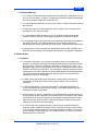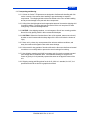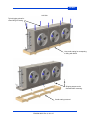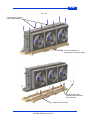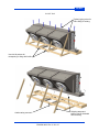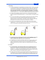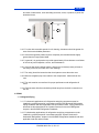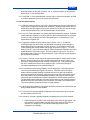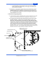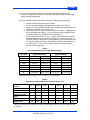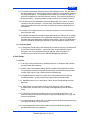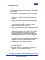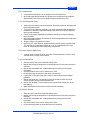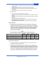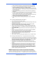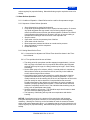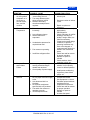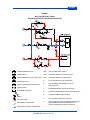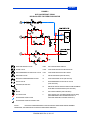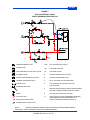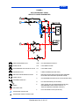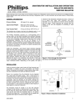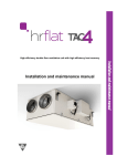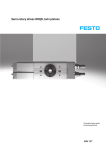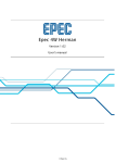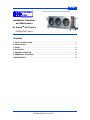
1
COLMAC When you want Quality, specify COLMAC! COLMAC COIL Manufacturing Inc. Installation, Operation, and Maintenance A+ SeriesTM Air Coolers ENG00019601 Rev A Contents 1. SAFETY INSTRUCTIONS .......................................................................................................... 3 2. INSTALLATION .......................................................................................................................... 5 3. PIPING....................................................................................................................................... 13 4. ELECTRICAL ............................................................................................................................ 19 5. GENERAL OPERATION........................................................................................................... 20 6. EMERGENCY SITUATIONS..................................................................................................... 28 7. MAINTENANCE ........................................................................................................................ 28 1 ENG00019601 Rev A, 10-6-15 COLMAC 2 ENG00019601 Rev A, 10-6-15 COLMAC 1. SAFETY INSTRUCTIONS To avoid serious personal injury, accidental death, or major property damage, read and follow all safety instructions in the manual and on the equipment. Maintain all safety labels in good condition. If necessary, replace labels using the provided part numbers. This is the safety alert symbol. It is used to alert you to potential personal injury hazards. Obey all safety messages that follow this symbol to avoid possible injury or death. DANGER indicates a hazardous situation which, if not avoided, will result in death or serious injury. WARNING indicates a hazardous situation which, if not avoided, could result in death or serious injury. CAUTION indicates a hazardous situation which, if not avoided, could result in minor or moderate injury. NOTICE indicates instructions that pertain to safe equipment operation. Failure to follow these instructions could result in equipment damage. PUR00019535 PUR00019560 PUR00019561 3 ENG00019601 Rev A, 10-6-15 COLMAC PUR00019536 PUR00019634 PUR00019628 PUR00019562 4 ENG00019601 Rev A, 10-6-15 COLMAC 1.1. Refrigerant Warning 1.1.1. A+ Series™ Evaporators may contain liquid refrigerant such as ammonia, R-22, R507, etc. For this reason, A+ Series™ Evaporators should be installed, operated and serviced by qualified refrigeration technicians only. 1.1.2. Liquid refrigerant causes burns, which may be fatal, if it leaks and comes in contact with a person. 1.1.3. Refrigerant vapor can cause asphyxiation and or tissue burns if released to the atmosphere in the vicinity of people. 1.1.4. Liquid refrigerant that is isolated in a pipe or equipment without an adequate means of pressure relief can rupture pipe or equipment if it is allowed to warm. 1.1.5. Hot refrigerant vapor, when injected into an evaporator containing cold refrigerant, will rapidly condense. This rapid condensation can accelerate liquid slugs to dangerously high energy levels that can rupture pipes, valves and other components. 1.1.6. Please refer to various manuals from organizations such as IIAR, ASHRAE, and RETA for more information concerning the safe operation of refrigeration equipment. 2. INSTALLATION 2.1. Inspection 2.1.1. Damage or Shortage – Upon receipt of equipment, inspect for shortages and damage. Any shortage or damage found during initial inspection should be noted on delivery receipt. This action notifies the carrier that you intend to file a claim. Any damaged equipment is the responsibility of the carrier, and should not be returned to Colmac Coil without prior notification. If any shortage or damage is discovered after unpacking the unit, call the deliverer for a concealed damage or shortage inspection. The inspector will need related paperwork, delivery receipt, and any information indicating his liability for the damage. 2.1.2. While Colmac will gladly provide information to assist with the process, the responsibility for filing such a claim is that of the purchaser or the purchaser’s consignee. 2.1.3. Specified Equipment – Check unit nameplate for: Electrical specifications to ensure compatibility with electrical power supply. Model Nomenclature and other information to match original order. 2.1.4. Each Colmac A+ Series™ Evaporator coil is shipped with a low-pressure nitrogen charge. Slightly open the Schrader valve located on the coil connection cap to detect the presence of the charge by listening for the nitrogen escaping through the valve. After this brief test, close the valve to maintain the nitrogen charge until the unit is ready to be connected to the system piping. 2.1.5. If the unit has lost its nitrogen charge, it may have been compromised during shipment. Before installation, pressure test the coil with dry nitrogen to ensure there is not a coil leak and report the loss of the shipping charge to Colmac. If the unit will not hold pressure, please obtain the unit’s serial number, then contact your Colmac Representative for a resolution. 5 ENG00019601 Rev A, 10-6-15 COLMAC 2.2. Transporting and Storing 2.2.1. Colmac A+ Series™ Evaporators are designed to facilitate safe handling with fork trucks or cranes. Use caution when handling to prevent damage to exposed components. The shipping skid should remain affixed to the unit to enable handling and to prevent damage to the pan and other components. 2.2.2. Lifting forks should be placed under appropriate areas of the wooden shipping skid for proper handling. The lifting skid may be used to lift the unit into place for either ceiling-hung or foot-mounted applications. 2.2.3. NOTICE: Use shipping container, or use hangers to lift unit into mounting position. Never lift unit by placing forklift in direct contact with drainpan. 2.2.4. CAUTION: Where the finned surface of the coil is exposed, extreme care should be taken to avoid contact with the sharp edges of the fins to minimize the chance of injury. 2.2.5. Store unit in a clean, dry area protected from adverse ambient conditions, and away from traffic and congestion that could cause damage. 2.2.6. Units stored for long periods of time should have the fan motor shaft turned several revolutions on a monthly basis to prevent the motor bearings from seizing. 2.2.7. Use shipping container and forklift to transport unit from truck to storage area and from storage area to installation area. See Submittal drawing for weight of unit. Center of gravity is for all practical purposes the same as the physical center of the unit. 2.2.8. Shipping crating and lifting points for the A+S, A+M, A+L standard, A+L 45°, A+L penthouse and A+R are shown in graphics that follow. 6 ENG00019601 Rev A, 10-6-15 COLMAC A+S Unit Typical rigging points for crane lifting or hoisting. Use cradle crating for transporting or lifting with forklift. Shipping straps can be discarded after mounting. Cradle crating removed. 7 ENG00019601 Rev A, 10-6-15 COLMAC A+M Unit Typical rigging points for crane lifting or hoisting. Use cradle crating for transporting or lifting with forklift. Shipping straps can be discarded after mounting. Cradle crating removed. 8 ENG00019601 Rev A, 10-6-15 COLMAC A+L Unit Typical rigging points for crane lifting or hoisting. Use fork lift pockets for transporting or lifting with forklift. Shipping straps and bracing can be discarded after mounting. Cradle crating removed. 9 ENG00019601 Rev A, 10-6-15 COLMAC A+L 45° Unit Typical rigging points for crane lifting or hoisting. Use fork lift pockets for transporting or lifting with forklift. Shipping straps and bracing can be discarded after mounting. Cradle crating removed. 10 ENG00019601 Rev A, 10-6-15 COLMAC A+L Penthouse Unit Typical rigging points for crane lifting or hoisting. Use fork lift pockets for transporting or lifting with forklift. Legs extensions are installed in the field prior to mounting. Cradle crating removed. 11 ENG00019601 Rev A, 10-6-15 COLMAC 2.3. Mounting 2.3.1. Units are designed to be suspended from the ceiling structure. Care must be taken to ensure that the ceiling structure is adequately strong to support the weight of the unit(s). Each unit has hangers to accept two threaded rods at each end of the unit, and two between each fan bay. A rod must be used for each hanger. The installer must ensure that the size of the rod used is adequate to support the unit for any local conditions (seismic, etc.). In some cases, additional hanger bracing may be required. 2.3.2. Hanger rod and hardware selection and size are to be provided by the design engineer using sound engineering practices. For proper support, all hangers must be used. 2.3.3. The unit must be lifted to the secured hanger rods and secured in place such that the top of the unit is level and each hanger provides equal support. Securely tightened double nuts with washers, or equivalent, must be used above and below the hanger hole to minimize the chances of loosening due to vibration. 2.3.4. Units can be provided with the Colmac Smart Hanger system which reduces installation time. Smart Hanger brackets and rails allow air cooler units to be hung from the ceiling without any personnel leaving the floor level. 2.3.5. Adjustable legs are provided optionally for floor mounted installations. For proper support, all legs must be supported on a level structural member and must be securely positioned such that the top of the unit will be level. 2.3.6. Depending on the location and installer preference, the shipping/handling skid may be removed before or after the unit is set in its final position. Once set in position, all legs should be bolted or welded to the supporting structure to prevent movement. 2.4. Location 2.4.1. For best placement, units should be located in the room opposite the doors, or placed in such a way that air from open doors cannot be drawn directly into the evaporator coil. Colmac recommends against the placement of units directly over doorways. If no alternative exists except placement over doorways, steps must be taken to restrict air infiltration and mitigate dockside moisture. 2.4.2. Unit(s) should be located to permit unobstructed airflow both to and from the unit. The intake face of the unit should be located at least one unit height away from any wall or other significant obstruction. The discharge area should be adequately free 12 ENG00019601 Rev A, 10-6-15 COLMAC and clear of obstructions, such as building structures, racks, or product, to permit the desired air throw. H H 2.4.3. For units with removable panels for coil cleaning, clearances should be greater for ease of access and ladder placement. 2.4.4. Units with hinged fan panels require a completely unencumbered area slightly greater than the hinged panel width. 2.4.5. In general, it is good practice to provide approximately 3-feet clearance on all sides of the unit to permit inspection, service, and maintenance. 2.4.6. If the unit has electric defrost heaters, allow for the necessary heater pull area at the end(s) of the unit, as noted on the unit drawings. 2.4.7. The unit(s) should be located so that the air pattern covers the entire room. 2.4.8. Minimize refrigerant pipe runs relative to the compressors. Minimize drain line runs. 2.4.9. The units must be mounted level for proper performance and refrigeration oil return. 2.4.10. Defrost water drain lines should be pitched away from the drain connections on the unit. 3. PIPING 3.1. Refrigerant Piping 3.1.1. For Ammonia applications, all refrigeration and piping components must be installed by qualified personnel in accordance with the IIAR Ammonia Refrigeration Piping Handbook and other applicable local and national codes. Piping practices for ammonia are also described in the “System Practices for Ammonia Refrigerant” chapter in the ASHRAE Refrigeration Handbook. 3.1.2. For Halocarbon applications, all refrigeration and piping components must be installed by qualified personnel in accordance with the “System Practices for Halocarbon Refrigerants” chapter in the ASHRAE Refrigeration Handbook and other applicable local and national codes. 13 ENG00019601 Rev A, 10-6-15 COLMAC 3.1.3. Piping is to be designed and supported independent of the evaporator to minimize the transmission of vibration, to permit expansion and contraction, and to impose no load on the evaporator connections. 3.1.4. Pipe sizes are to be established according to good engineering design practices, taking into account all applicable facets of the system: the connection size provided by Colmac should not be used to determine the system piping. 3.1.5. The nitrogen holding charge should be permitted to remain intact as long as possible. When ready to connect the refrigerant piping, slowly vent the nitrogen charge to the atmosphere, and then remove the temporary connection caps. Note that these temporary capping provisions are not intended for refrigeration service and must be removed prior to placing the coil in service. 3.1.6. Standard coil connections for units having all aluminum coil construction utilize bimetallic couplings with carbon steel stubs which can be welded directly to system piping after removal of the factory welded cap. Remove cap so that at least 4” of the connection stub remains. Do not weld within 4” of the bimetallic coupler. WELDED PLUG SYSTEM PIPING BIMETALLIC COUPLING DO NOT WELD IN THIS AREA COIL BLOCK 4.0000 3.1.7. Carbon steel connections will be Schedule 80 pipe for connections less than or equal to 1-1/2” in diameter or Schedule 40 for connections 2” in diameter and greater. 3.1.8. Standard coil connections for halocarbon systems are copper “sweat” connections. 3.1.9. Prior to charging the system with refrigerant, the entire system must be pressure tested to ensure there are no leaks and evacuated to remove moisture. 3.2. Thermal Expansion Valves 3.2.1. Perform the following tasks when installing a thermal expansion valve (TXV) on a direct expansion system: Confirm that the distributor orifice and retainer wire is in place and was not dislodged during shipping and handling. Note that some hot gas defrost systems will have a side port for hot gas located between the distributor orifice and the distributor. For ammonia systems, confirm that the discharge tube is removed from the outlet of the TXV. Install the expansion valve immediately adjacent to the distributor with no elbows, valves, or fittings in between. If a side port must be provided, the orifice must be removed to the upstream side of the port, adjacent to the TXV. Connect the equalizer tube. Secure the expansion valve bulb directly on a horizontal length of pipe, as close to the suction header as possible, but not at a trap nor downstream from a trap. The 14 ENG00019601 Rev A, 10-6-15 COLMAC preferred location on the pipe is in the 3, 4, 8, or 9 o’clock position. Do not place the bulb at the 6 or 12 o’clock positions. 3.2.2. CAUTION: It is recommended that a suction trap, or suction accumulator, be used on all direct expansion systems for compressor protection. 3.3. Hot Gas Defrost Piping 3.3.1. With this method of defrost, some of the hot discharge gas from the compressor is routed into the evaporator instead of the condenser. During hot gas defrost, the coil temperature should be high enough to melt frost and ice on the coil, but low enough so that heat and steam loss to the refrigerated space are minimized. 3.3.2. Only 1/3 of the evaporators in a system should be defrosted at one time. Example: if total evaporator capacity is 100 tons (352 kW), then evaporators with no more than 33 tons (116 kW) of capacity should be defrosted at once. Consult factory if your system does not permit this. 3.3.3. Suggested methods of piping can be seen in Figure 1 thru 4. To maintain uninterrupted gas flow and a clear, fully drainable condensing surface, hot gas is always fed through the evaporator from the top down. For a bottom feed coil, this involves feeding the suction header with hot gas, as is seen in Figure 1. For a top feed coil, like in a Top Feed Recirculated or a Direct Expansion evaporator, the liquid header/distributor is fed with hot gas. This can be seen in Figure 2 for Top Feed Recirculated and in Figure 3 for Direct Expansion. Figure 4 shows hot gas piping for gravity flooded evaporators. 3.3.4. Figures 1 through 4 show control valve groups arranged for forward-cycle hot gas defrost. With this method, hot gas is piped in series through the unit cooler, first through the hot gas drainpan loop, and then through the coil. This method requires the use of a third line to the air unit to supply hot gas. Consult the Factory for information regarding other hot gas defrost options. 3.3.5. For evaporators with cooling capacity 15 tons and greater, a soft start solenoid valve is recommended (See Figures 1 through 4). Soft Start uses a secondary, smaller solenoid capable of letting a reduced amount of hot gas into the defrost system at the beginning of defrost, while the main hot gas solenoid remains closed. Once the system is up to a pre-designated pressure (~40 psig), the main hot gas solenoid is opened, allowing the system to approach its normal operating pressure. The Soft Start system eases the unit cooler into the defrost cycle, limiting unwanted problems like check valve chatter, pipe movements, and most of all, liquid hammer. This control method is particularly useful on larger systems. 3.3.6. All hot gas piping located in cold spaces should be insulated, as well as all hot gas piping located outdoors in cold climates. 3.3.7. The amount of hot gas supplied will depend on the inlet pressure of the hot gas, and the capacity of the air unit. 3.3.8. Ammonia - Hot gas is typically supplied to evaporators by one of two methods: Install a pressure regulator in the compressor room at the hot gas takeoff. Set the regulator to approximately 100 psig (689.5 kPa), then size the piping to achieve 75 to 85 psig (517 to 586 kPa) condensing pressure at the evaporators, accordingly. 15 ENG00019601 Rev A, 10-6-15 COLMAC In branches leading to each evaporator from the main hot gas line, install a pressure regulator set at approximately 75 to 85 psig (517 to 586 kPa), then size the branches accordingly. 3.3.9. Halocarbon – Hot gas piping is typically sized to accommodate twice the normal refrigerant mass flow from the evaporator. Pressure drop is not as critical for the Halocarbon defrost cycle, so refrigerant velocity can be used as the criterion for line size. It is suggested that hot gas lines are sized for the refrigerant velocity between 1000 to 2000 ft/min (5 to 10.2 m/s). 3.4. Water Defrost Piping (Supply Water) 3.4.1. Water defrosting consists of distributing water over the coil surface for a very short period of time, then draining the water from the piping before freezing can occur. 3.4.2. The figure below shows typical water defrost piping and controls layout for water defrosted evaporators. A solenoid valve in the water supply line to one or more defrost units, opens under control of an automatic timer to allow water to the units. Water flow to unit water distribution pans is metered by manually adjusted balancing or globe valves. A length of 1/4 in OD tubing is installed as shown in all of the figures to drain the supply piping when the solenoid valve closes, and the defrost period ends. A slope of 1/2 in. per foot is recommended for all supply lines to maintain adequate drainage. All four unit coolers are piped similarly, with the major exception being the A+D unit cooler. The A+D has two water distribution pans per side and two drainpans, and as such, requires additional consideration when piping. Balancing Valve at each Defrost Connection Master Balancing Valve Solenoid Valve Gate Valve Water Supply Supply/Drain Lines Pitched ½” per Foot Hose To Drain Units Individually Trapped To Prevent Drawback of Warm Air 16 ENG00019601 Rev A, 10-6-15 COLMAC 3.4.3. For normal conditions, Table 2 may be used to select water supply sizes. However, if supply water pressure is lower than 30 psig (207 kPa), then the supply piping should be sized larger. 3.4.4. The following procedure should be used when sizing supply water piping: Choose a preliminary pipe size from Table 2. List the equivalent lengths of all fittings and valves given in Table 3. Add the sum of all equivalent lengths, to the lengths of all straight pipe runs. Divide the total length from step 3 by 100. Obtain the Pressure Loss per 100 feet of pipe from Table 6. Multiply this by the number obtained in Step 4. (This is the pressure loss through the pipe, valves and fittings due to length and flow impedances) List the change in elevation (+ is up, - is down) of all vertical pipe runs and determine pressure losses in pipe from the gain in elevation from Table 4. The sum of Step 5, Step 6 plus a 5 psig allowance, is the total pressure loss through pipe valves and fittings, and must not exceed the water pressure in the supply main. If it does exceed supply pressure, recalculate steps 2 through 7 with a larger pipe. Table 2 Recommended Pipe Size, Water Defrost Supply Pipe Size (IPS, inches) 1 1-1/4 1-1/2 2 2-1/2 3 4 Schedule 40 Steel GPM L/s 3 to 7 (0.2 to 0.4) 8 to 15 (0.5 to 0.9) 15 to 22 (1.0 to 1.4) 23 to 40 (1.5 to 2.5) 41 to 70 (2.6 to 4.4) 71 to 130 (4.5 to 8.2) 131 to 250 (8.3 to 15.8) Copper & Plastic GPM L/s 3 to 7 (0.2 to 0.4) 8 to 12 (0.5 to 0.8) 13 to 20 (0.9 to 1.3) 21 to 45 (1.4 to 2.8) 46 to 80 (2.9 to 5.0) 81 to 130 (5.1 to 8.2) 131 to 270 (8.3 to 17.0) * Based on pressure loss of 1 to 4 ft / 100 ft (100 to 400 Pa/m) Table 3 Equivalent Length of Water Defrost Pipe Fittings, Feet Pipe Size, (IPS, inches) Solenoid 90° Elbow Tee Coupling or Gate Valve Globe Valve Angle Valve 1 1-1/4 1-1/2 2 2-1/2 3 4 15.0 5.2 6.6 16.0 6.6 8.7 16.0 7.4 9.9 18.0 8.5 12.0 18.0 9.3 13.0 20.0 11.0 17.0 -13.0 21.0 0.8 1.1 1.2 1.5 1.7 1.9 2.5 29.0 17.0 37.0 18.0 42.0 18.0 54.0 21.0 62.0 22.0 79.0 28.0 110.0 38.0 Add equivalent length of all fittings to length of same straight pipe to obtain total length for use on Table 8. 17 ENG00019601 Rev A, 10-6-15 COLMAC Table 4 Pressure Loss Due to Elevation 5 2 Elevation, (ft) Pressure Loss, (psi) 7 3 9 4 12 5 16 7 23 10 35 15 46 20 60 26 275 6 550 8 Table 5 Water Defrost Recommended Drain Line Sizes Water Flow, (GPM) Pipe Size, (IPS, inches) 15 2 25 2.5 42 3 63 3.5 89 4 170 5 Table 6 Water Capacity, GPM Sch 40 Pipe Pipe Size (IPS, Inches) 1 1-1/4 1-1/2 2 2-1/2 3 4 2 8 17.4 25.9 51.4 80.9 144.3 292 5 12.8 26.9 41 79.6 127.6 227.6 469.6 Pressure Loss Per 100 ft, psi 10 15 20 30 19.1 24 27.8 33.9 29.7 49.5 57.4 70 60 74.1 85.5 106.5 116.7 144.7 166.9 203.2 186 229 264.6 330.8 331.6 407.2 467.7 575.4 671.8 826.8 961.7 -- 50 44.5 91.9 140 268 390 --- ** For SCH 40 steel pipe. Multiply psig values by 0.86 for PVC or Copper Pipe. Notes: If the water supply pressure is unknown, it may be measured by installing a gauge and valve at the “takeoff” point. The pressure should be measured with water flowing near the desired rate. In some instances, (as with 2” pipe), it may be desirable to use a solenoid valve to fit the next size smaller pipe. (As with all valves and fittings, determine the correct equivalent length to calculate pressure loss) 3.5. Defrost Drain Piping 3.5.1. Drain connections from the drainpan should be individually trapped. Individual trapping prevents warm air from being drawn back through the drain pipe of nondefrosting units. Drain line size should be at least equivalent to the unit cooler drain connection size. For Water Defrost, use Table 5 for sizing defrost drain line sizes. 3.5.2. Within the refrigerated space, the drain line should be pitched sharply down, at least 1/2 in/ft (4 cm/m) and be as short as possible. It should also be heat traced and insulated along its entire length. Traps should be located in a warm area outside the refrigerated space. Any traps or extensive lengths of pipe located outdoors must be heated and insulated to prevent freeze up. Any such heater should be connected for continuous operation. Standard industry practice is for 20 Watts / linear foot of pipe @ 0°F (-17.8°C) and 30 Watts / linear foot of pipe @ -20°F (-28.9°C). 18 ENG00019601 Rev A, 10-6-15 COLMAC 3.5.3. The trap requires static head to overcome the resistance to flow. For this reason, it should be located in the vertical piping at least 2’ below the unit (preferably outside of the refrigerated space). The trap should not be heated if it is located in a space in which the temperature is continuously above freezing. This avoids the possibility of boiling the trap dry. The piping should include a cross or tee to facilitate cleanout. 3.5.4. All piping should be adequately supported independent of the unit so no load is imposed on the pan connection. In some cases, consideration should be given to using a union at/near the pan connection to enable disconnecting the drain line for maintenance. 3.5.5. Caution- Do not apply torque to the drain pan connection; use two wrenches to secure the pipe union. 3.5.6. Drainpan and drain lines should be inspected routinely for evidence of ice buildup. Periodic manual maintenance of icing drainpans and drain lines may be required if less than ideal frosting/defrosting conditions have existed. See the Troubleshooting chart for information regarding the diagnosis of freezing drainpans and drain lines. 3.6. Connection Sizes 3.6.1. Refrigerant, defrost supply, and defrost drain connection sizes are pre-determined by the factory and the customer. Connection sizes are automatically selected through the use of our proprietary selection software. More information on connection sizing can be found in the ASHRAE Refrigeration Handbook. 4. ELECTRICAL 4.1. General 4.1.1. All wiring must be performed by qualified personnel, in compliance with national and local codes and standards. 4.1.2. Refer to the unit nameplate and the specific certified wiring drawings for details. The nameplate contains the required electrical power characteristics and the serial number, which can be cross- referenced to the certified prints. 4.1.3. Standard motors for A+R, A+S, and A+D air coolers include internal thermal overload protection. Custom motors may require external overload relays. 4.1.4. Standard motors for A+L and A+M air coolers do not include thermal overload protection. 4.1.5. Select feeder circuit protection, branch circuit protection, motor contactors, overload relays, and wire sizes in accordance with applicable local and national codes. 4.1.6. Field wiring connections are made to at a common electrical enclosure. The electrical enclosure and internal components may differ depending on unit type and customer specification. 4.1.7. Complete electrical controls with a UL 508 Enclosed Industrial Control Panel listing can be provided at the customer’s request. 4.1.8. Units equipped with electric defrost and/or special electrical controls will be provided with specific wiring diagrams. 19 ENG00019601 Rev A, 10-6-15 COLMAC 4.2. Variable Frequency Drives 4.2.1. There are many factors that can contribute to the success or failure of VFDs applied to Colmac equipment, most of which are the direct responsibility of the installing electrical contractor. The general design requirements listed below represent the minimum criteria for proper VFD system design. Care should be taken to follow all of the drive manufacturer’s recommendations and all applicable electrical codes and standards. Motors - Ensure that “Inverter Duty” rated motors are used in situations where VFDs are applied. Colmac motors that are specified as “Inverter Duty” will comply with the National Electrical Manufacturers Association (NEMA) requirements for VFD compatible motors. This type of motor construction, which includes a special winding wire insulation system as well as phase paper installed between the windings, is the accepted industry standard for inverter duty motors. Grounding - It is essential that the electrical system, building steel, motor and drive be properly grounded. The National Electric Code (NEC) describes the minimum requirements for grounding and bonding an electrical system for safe operation. In addition to providing a ground from the drive chassis and motor frame to earth ground, Colmac recommends a separate ground conductor from the motor frame to the VFD ground bus. Proper grounding is a critically important means of mitigating bearing current failures. Cabling – Conductors should be rated and sized appropriately for the motor load, voltage drop, and environmental conditions. Colmac recommends the use of shielded VFD cable for several reasons. VFD cables are specifically designed for higher voltages, manufactured to higher quality standards and provide a more consistent insulation wall thickness. VFD specific cables are designed to withstand the reflected wave and resulting corona effects. Also, minimizing the length of the conductors from the drive to the motor will help reduce the magnification of the reflected wave. Shielded cables can also help to reduce bearing pitting by directing the destructive current to ground. Both ends of the shield should be bonded and care should be taken to maintain this bond when there are interruptions in the conductor run (i.e. local motor disconnect). Carrier Frequencies – Colmac recommends setting the drive carrier frequency as low as possible (typically 2 kHz). Lower carrier frequencies result in higher levels of audible VFD noise, but will help to reduce destructive bearing currents. Line and Load Reactors – Ensure that the drive manufacturer’s recommendations are followed with regard to sizing and use of line and load reactors. Issues with line voltage imbalance, reflected wave phenomena, switched power factor correction capacitors, and long line lengths can be mitigated with properly sized line and load reactors. Line lengths should be minimized whenever possible. Motor Speed – Generally it is not recommended to over speed motors or to operate motors at less than 25% of the motor rated speed. 5. GENERAL OPERATION 5.1. Before Startup - Following is a representative checklist of items to be checked prior to startup. It is not, nor is it intended to be, a comprehensive checklist for the many varying 20 ENG00019601 Rev A, 10-6-15 COLMAC industrial refrigeration systems. Consult with a qualified system startup expert for assistance. Make sure unit is mounted securely using all hangers, and is level. Make sure unit voltage agrees with supply voltage. Make sure system is wired correctly and in accordance with the guidelines laid out in this IOM, as well as local and national standards that may apply. Check torque on all electrical connections. Confirm the supply voltage is within 10% of design and the phase-to-phase imbalance is within 2%. Make sure that all fan set screws are tight. Check fan direction and amperage. Make sure all piping is done completely and in accordance with the guidelines laid out in this IOM, as well as in accordance with standard good practice. Make sure that liquid supply suction and hot gas supply (as applicable) service valves are open. Check drainage of drain pan and drain piping by pouring water into drainpan. Check water defrost distribution – see “Regulating Water Flow Rate”. (Water Defrost units only) 5.2. After Startup Check the compressor for possible overload immediately after start up. Check fan rotation of all fans to make sure air is moving in proper direction. Check the air unit operation for proper refrigerant charge. Confirm the room thermostat and/or control system are functioning properly. Look and listen for any excessive vibration, severe valve chatter, water hammer, or moving pipes, and correct as necessary. Heavy moisture loads are usually encountered when starting a system for the first time. This will cause rapid frost buildup on the unit. During the initial pulldown we suggest that the frost buildup be watched and that the unit be defrosted manually as required. Evaporators with liquid feed orifices for liquid overfeed must have liquid refrigerant supplied to the coil inlet at a pressure 5 psig (35 kPa) above saturated suction pressure, and at a temperature not exceeding 30°F (16.7°C) above saturated suction temperature. Please consult factory if conditions exceed these recommendations. 5.3. Field Adjustments - Perform the following functions when commissioning A+ Series™ evaporators, based on the refrigerant feed system and defrost technique being employed on the particular unit. These instructions are not, nor are they intended to be, a comprehensive list of tasks required to successfully commission all A+ Series™ evaporators. Consult with a qualified system startup expert for assistance. 5.3.1. Recirculated & Controlled Pressure Receiver Feed: Open hand expansion valves (HEVs) slowly and observe frost/condensate formation on all return bends, top and bottom alike. The proper setting may be achieved by observing the frost or condensate on all return bends and opening the HEV until all return bends are evenly wetted or frosted. Alternatively, if the defrost relief regulator is connected to the liquid line and is equipped with a gauge, set the HEV to achieve a 5 psi rise in pressure when the liquid solenoid valve is energized. 21 ENG00019601 Rev A, 10-6-15 COLMAC 5.3.2. Flooded Feed: Verify that the liquid level is at the design level in the surge drum. Open and adjust the liquid feed HEV to allow for the solenoid to be energized approximately 70% of the time at design temperature difference (TD). 5.3.3. Direct Expansion Feed: After room temperature has been achieved, check the superheat, and adjust the thermal expansion valve. If the coil is being starved, resulting in too much superheat at the desired room temperature, reduce the superheat setting of the valve by turning the adjusting stem counter-clockwise. If there is not enough superheat, increase the setting by turning the adjusting stem clockwise. After waiting approximately 30 minutes, re-check the superheat and re-adjust the thermal expansion valve. Repeat until the unit operation is stable. Note that 10°F is the minimum superheat required to fully stroke a conventional TXV and that 10°F superheat requires an 11 or 12°F split between the room return air temperature and the evaporating temperature. 5.3.4. Brine, Glycol or Water Feed: Vent the system, bleed off all air, and check for water hammer. Verify the feed solenoid valve or mixing valve function. 5.3.5. Hot Gas Defrost: Allow the unit to frost, then initiate the defrost cycle. Monitor the leaving air temperature. It should show a rise if the pump-out time is sufficient. Monitor the condensate flow. It should diminish to a trickle prior to hot gas termination. Check the bottom of the coil for residual ice or frost. Do not allow long hot gas times that cause coil steaming. If more than 15 minutes of hot gas is required, there may be system design problems. Monitor the bleed time. The pressure of the coil should be within 25 psig of suction pressure by the end of the bleed cycle. Monitor the fan delay. The free water on the coil should be frozen prior to the fans starting. Make adjustments to the various function times as necessary 5.3.6. Electric Defrost: Allow the unit to frost, then initiate the defrost cycle. Monitor the leaving air temperature. It should show a rise if the pump-out time is sufficient. Monitor the condensate flow. It should diminish to a trickle prior to heater termination. Check the bottom of the coil for residual ice or frost. Do not allow long heater on times that cause coil steaming. 22 ENG00019601 Rev A, 10-6-15 COLMAC Verify the operation of the defrost termination thermostat and remove the start-up jumper, if used. Verify that all of the heaters are working by checking the amp draw. Monitor the fan delay. The free water on the coil should be frozen prior to the fans starting. Make adjustments to the various function times as necessary 5.3.7. Water Defrost: Allow the unit to frost, then initiate the defrost cycle. Monitor the leaving air temperature. It should show a rise if the pump-out time is sufficient. Monitor the water flow and check for even flow coverage, overflows or excessive splashing. Check the coil for any residual frost or ice. Monitor the fan delay. The free water on the coil should be frozen prior to the fans starting if the unit is in a freezer. Make adjustments to the various function times and flow rates as necessary. 5.4. Defrost Selection 5.4.1. Determination of defrost should be based on several variables. Energy costs, availability of sufficient supply of water or hot gas, system first cost considerations, and last but not least, the refrigerated spaces operating temperature. Air defrost can certainly not be applied in cold storage applications with temperatures below 38°F. Likewise, the use of a hot gas system in a +42°F (5.6°C) room is not appropriate. Table 1 shows recommended guidelines for defrost system selection relative to refrigerated room temperature. Table 1 Recommended Room Temperature Ranges for Different Defrost Types Temperature Range Low Temp (<20°F [-6.7°C]) Medium Temp (<38°F and >20°F [-6.7°C]) High Temp (>38°F [7.2°C]) Hot Gas Defrost YES YES N/A Water Defrost YES YES N/A Electric Defrost YES YES N/A Air Defrost NO NO YES 5.5. Hot Gas Defrost Operation 5.5.1. Condition of Operation - Hot Gas Defrost can be used for any design criteria, including Low-Temp and Medium-Temp. 5.5.2. Proper hot gas defrost operation is entirely dependent on hot refrigerant latent condensation during the defrost operation. This requires hot gas to be delivered to the evaporator at a saturation pressure necessary for condensation to occur during defrost. Typical design hot gas saturation temperatures run between 50°F (10°C) to 60°F (15.6°C). Table 7 shows the equivalent saturation pressures, for a variety of refrigerants, required at the evaporator to accommodate this temperature range. 23 ENG00019601 Rev A, 10-6-15 COLMAC Table 7 Hot Gas Pressures for Various Refrigerants Refrigerant R22 Ammonia (R717) R507a R404a Hot Gas Pressure @ Evaporator ~85 to100 psig (~688 to 791 kPa) ~75 to 90 psig (~619 to 722 kPa) ~105 to 125 psig (~826 to 964 kPa) ~105 to 125 psig (~826 to 964 kPa) 5.5.3. Hot Gas Supply line pressure should be maintained at less than the system condensing pressure. This serves two purposes; the first being decreased energy losses due to excessive heat gain, and the second being that condensing pressure has a tendency to fluctuate with ambient conditions and with the load. Maintaining the Hot Gas Supply pressure at less than the system condensing pressure helps ensure a constant Hot Gas pressure at the evaporator. 5.5.4. Sequence of Hot Gas Defrost Operation 5.5.4.1. Recirculated Bottom Feed Evaporators (See Figure 1) Close Liquid Solenoid and continue operating fan motors. Pump down liquid refrigerant from coil for a period of approximately 15 minutes (or as long as required). Any cold liquid refrigerant remaining in the coil at the beginning of defrost will greatly reduce the effectiveness of the hot gas defrost operation and can extend the time required for defrost. Evidence of residual liquid refrigerant can be seen in the form of uneven melting or the absence of melting on the lower tubes of the evaporator coil. Stop fan motors. Open Hot Gas Pilot Solenoid to close Gas-Powered Suction Stop Valve. On Coils of 15 tons cooling capacity and larger, open Soft Start Hot Gas Solenoid to gradually bring coil up to near defrost pressure. Open Hot Gas Solenoid to start defrost. Duration of defrost should be long enough to clear coil and pan. Extending the defrost period longer than this is not necessarily better. Close Hot Gas Solenoid (and Soft Start Hot Gas Solenoid if applicable) to end defrost. Open Equalizing Bleed Valve to gradually bring evaporator back down to suction pressure. Close Hot Gas Pilot Solenoid to open the Gas-Powered Suction Stop Valve. At the same time, open the Liquid Solenoid to start cooling the coil. After a delay to refreeze remaining water droplets on the coil, restart the fans. 5.5.4.2. Recirculated Top Feed and Direct Expansion Evaporators (See Figure 2 and 3) Close Liquid Solenoid and continue operating fan motors. Pump down liquid refrigerant from coil for a period of approximately 15 minutes (or as long as required). Any cold liquid refrigerant remaining in the coil at the beginning of defrost will greatly reduce the effectiveness of the hot gas defrost operation. Evidence of residual liquid refrigerant can be seen in the form of uneven melting or the absence of melting on the lower tubes of the evaporator coil. Stop fan motors. 24 ENG00019601 Rev A, 10-6-15 COLMAC Open Hot Gas Pilot Solenoid to close Gas-Powered Suction Stop Valve. On Coils of 15 tons cooling capacity and larger, open Soft Start Hot Gas Solenoid to gradually bring coil up to near defrost pressure. Open Hot Gas Solenoid to start defrost. Duration of defrost should be long enough to clear coil and pan. Extending the defrost period longer than this is not necessarily better. Close Hot Gas Solenoid (and Soft Start Hot Gas Solenoid if applicable) to end defrost. Energize the Defrost Relief Regulator to the wide open position to gradually bring the evaporator back down to suction pressure (equalize). Close Hot Gas Pilot Solenoid to open the Gas-Powered Suction Stop Valve. At the same time, de-energize the Defrost Regulator Valve. Open the Liquid Solenoid to start cooling the coil. After a delay to refreeze remaining water droplets on the coil, restart the fans. 5.5.4.3. Gravity Flooded Evaporators (See Figure 4) Close Liquid Solenoid and stop fan motors. Open Hot Gas Pilot Solenoid to close the two Gas-Powered Stop Valves in the coil liquid and suction lines. On Coils of 15 tons cooling capacity and larger, open Soft Start Hot Gas Solenoid to gradually bring coil up to near defrost pressure. Open Hot Gas Solenoid to start defrost. Duration of defrost should be long enough to clear coil and pan. Extending the defrost period longer than this is not necessarily better. Close Hot Gas Solenoid (and Soft Start Hot Gas Solenoid if applicable) to end defrost. Energize the Defrost Relief Regulator to the wide open position to gradually bring the evaporator back down to suction pressure (equalize). Close Hot Gas Pilot Solenoid to open the Gas-Powered Suction Stop Valves. At the same time, de-energize the Defrost Regulator Valve. Open the Liquid Solenoid. After a delay to refreeze remaining water droplets on the coil, restart the fans. 5.5.4.4. Setting Hot Gas Defrost Timer. Time periods should be set as follows: Length of defrost should be set to the minimum time necessary to melt all frost. Defrost operation beyond this point will convert liquid water to steam, leading to secondary condensation and freezing on non-heated areas of the unit cooler and introduced unwanted heat gain into the controlled space. Depending on frost loading conditions, defrost duration can typically last anywhere from 12 to 20 minutes, and in most cases, should never exceed 30 minutes. Actual defrost times must be determined from careful observation of defrost operation and adherence to the previously mentioned guidelines. Frost is usually heaviest on the air-entering side of the coil, and inspection of fins on this side can usually be used to determine if complete defrost has occurred. Periodic observation of the defrost cycle throughout the year is necessary to maintain a properly operating defrost system. NOTICE: Once frost turns to ice, the amount of time required to melt increases. Incomplete defrosting may allow excessive ice to build up which could damage the machinery. Allowing ice to build up on the fan blades will result in excessive vibration which could lead to catastrophic failure. It is imperative that the end user inspect the unit 25 ENG00019601 Rev A, 10-6-15 COLMAC coolers regularly for proper defrosting. Manual defrosting may be required to remove ice buildup. 5.6. Water Defrost Operation 5.6.1. Condition of Operation - Water Defrost can be used for all temperature ranges. 5.6.2. Sequence of Water Defrost Operation Stop refrigeration by closing liquid solenoid. Pump down liquid refrigerant from coil for a period at least equal to 15 minutes. Any liquid refrigerant that may remain in the coil during defrost will greatly reduce the effectiveness of the hot gas defrost operation. Evidence of residual liquid refrigerant during defrost can be seen in the form of uneven melting or the absence of melting on the lower tubes of the evaporator coil. Stop fan motors. Open water valve for the necessary time of defrost. Allow water to drain from fins. Bleed evaporator pressure back down to normal suction pressure. Start refrigeration to cool the evaporator. Restart fan motors. 5.6.3. Setting Water Defrost Timer 5.6.3.1. Instructions for adjustment of Defrost Timer should be shown in the Timer User’s Manual. 5.6.3.2. Time periods should be set as follows: The delay period for pump down and fan stoppage is approximately 1 minute. With very large coils where time for pump-down after shutting the refrigerant solenoid valve may be longer, the delay period may be longer. Set the delay accordingly. Set the water spray to five minutes, initially. In actual practice, it may take as little as three minutes to clear frost from the coil, and only in rare instances would it take as long as fifteen minutes. Actual defrost times must be determined from careful observation of defrost operation and adherence to the previously mentioned guidelines. Frost is usually heaviest on the air-entering side of the coil, and inspection of fins on this side can usually be used to determine if complete defrost has occurred. Periodic observation of the defrost cycle throughout the year is necessary to maintain a properly operating defrost system. If more than fifteen minutes is required to completely remove frost, it is an indication that something may be wrong, such as inadequate water supply. Set drain period for two minutes. This should be ample time for water to drain off of the coil before starting up the fans. The frequency of defrosting will vary with room temperature and relative humidity. NOTICE: Once frost turns to ice, the amount of time required to melt increases. Incomplete defrosting may allow excessive ice to build up which could damage the machinery. Allowing ice to build up on the fan blades will result in excessive vibration which could lead to catastrophic failure. It is imperative that the end user inspect the unit coolers regularly for proper defrosting. Manual defrosting may be required to remove ice buildup. 26 ENG00019601 Rev A, 10-6-15 COLMAC 5.6.4. Specifying Water Defrost Temperature 5.6.4.1. Adequate temperature of the water defrost supply must be maintained throughout the defrost cycle to guarantee adequate defrost under varying room temperature conditions. Recommended water temperatures as a function of room temperature are found in Table 8. Table 8 Recommended Water Defrost Temperatures Room Temperature -20°F to 30°F (-28.9°C to -1.1°C) 30°F to 32°F (-1.1°C to 0°C) 32°F (0°C) and up Water Temperature At least 50°F (10°C) At least 45°F (7.2°C) At least 40°F (4.4°C) 5.6.5. Regulating Water Flow Rate 5.6.5.1. Water flow rate is controlled by adjusting the balancing valve at each unit. Adjust flow rate to fully saturate the coil fin surfaces in defrost water, making sure not to overflow the distribution pan, which can result in undesirable splashing. In some areas, the water pressure may become very low during daytime hours due to usage in the same building or neighborhood. In such instances, it may be necessary to set the timer to defrost when adequate water pressure is available. 5.7. Electric Defrost Operation 5.7.1. Condition of Operation - Electric Defrost can be used for any design criteria, including Low-Temp, Medium-Temp, and High-Temp Applications. 5.7.2. Sequence of Electric Defrost Operation Stop refrigeration by closing liquid solenoid. Pump down liquid refrigerant from coil for a period at least equal to 15 minutes. Any liquid refrigerant that may remain in the coil during defrost will greatly reduce the effectiveness of the electric defrost operation. Evidence of residual liquid refrigerant during defrost can be seen in the form of uneven melting or the absence of melting on the lower tubes of the evaporator coil. Stop fan motors. Energize power to electric defrost heating elements for the necessary time of defrost. De-energize power to heating elements when defrost is complete. Start refrigeration to cool the evaporator. Restart fan motors. 5.7.3. Setting Electric Defrost Timer - Time periods should be set as follows: Length of defrost should be set to the minimum time necessary to melt all frost. Defrost operation beyond this point will convert liquid water to steam, leading to secondary condensation and freezing on non-heated areas of the unit cooler and introduced unwanted heat gain into the controlled space. Average defrost times can vary anywhere from fifteen to twenty minutes, and in most cases, should never exceed thirty minutes. Actual defrost times must be determined from careful observation of defrost operation and adherence to the previously mentioned guidelines. Frost is 27 ENG00019601 Rev A, 10-6-15 COLMAC usually heaviest on the air-entering side of the coil, and inspection of fins on this side can usually be used to determine if complete defrost has occurred. Periodic observation of the defrost cycle throughout the year is necessary to maintain a properly operating defrost system. NOTICE: Once frost turns to ice, the amount of time required to melt increases. Incomplete defrosting may allow excessive ice to build up which could damage the machinery. Allowing ice to build up on the fan blades will result in excessive vibration which could lead to catastrophic failure. It is imperative that the end user inspect the unit coolers regularly for proper defrosting. Manual defrosting may be required to remove ice buildup. 5.8. Air Defrost Operation 5.8.1. Condition of Operation - Air Defrost can be used for High-Temp installations only. 5.8.2. Sequence of Air Defrost Operation Pump down liquid refrigerant from coil for a period at least equal to 15 minutes. Any liquid refrigerant that may remain in the coil during defrost will greatly reduce the effectiveness of the air defrost operation. Evidence of residual liquid refrigerant during defrost can be seen in the form of uneven melting or the absence of melting on the lower tubes of the evaporator coil. Allow fans to continue operating for the necessary time of defrost. Re-introduce refrigerant into evaporator and re-start refrigeration to cool the evaporator. 5.8.3. Setting Air Defrost Timer 5.8.3.1. Time periods should be set as follows: Time to defrost should be just long enough to melt all frost. 6. EMERGENCY SITUATIONS 6.1. During normal operation the units described in this IOM contain either ammonia or one of several possible halocarbon refrigerants. There are hazards and risks associated with all refrigerants. Refrigerant leaks can cause an emergency situation. Refer to the facility “Emergency Planning Policy” and “Hazardous Chemical Communication Policy” for the proper methods of dealing with any potential emergency situation resulting from a refrigerant leak. 7. MAINTENANCE 7.1. WARNING: Prior to any maintenance being performed, unit must be locked out and tagged out per the Lockout/Tag Out policy of the facility where installed. 7.2. Note that equipment may be damaged by incompatible cleaning agents or water condensate from defrost that is contaminated by airborne impurities. It is the responsibility of the owner/operator to be familiar with these chemicals and the room environment and to select compatible agents and materials of construction. 7.3. Refer to the certified submittals for a listing of the materials used in the specific evaporator in question. 28 ENG00019601 Rev A, 10-6-15 COLMAC 7.4. Consult with a qualified chemical/corrosion expert to ensure compatibility and to develop a plan to address any special circumstances, such as airborne impurities. 7.5. System Maintenance Schedule (recommended maximum time periods) 7.5.1. Every month The system should be periodically checked for proper defrosting and defrost timing due to variations in the quantity and pattern of frost. Frost accumulation is dependent on the following: temperature of the space, type of product stored, product loading rate, traffic, moisture content of air entering conditioned space, etc. It may be necessary to periodically adjust number of defrost cycles or duration of each defrost cycle to accommodate these varying conditions. 7.5.2. Every 6 months Check refrigeration system for charge level, oil level, and any evidence of leaks. Tighten all electrical connections. Check operation of control system and proper functioning of defrost solenoids, drain line heaters, thermostats, etc. Check that all safety controls are operating appropriately. 7.6. Evaporator Maintenance Schedule (recommended maximum time periods) 7.6.1. Every 6 months Clean the coil surface. Inspect defrost drain pan. Clean if necessary. Check for proper drainage. For Water Defrost, inspect water defrost distribution pans. Clean if necessary. Inspect all insulated supply and drain lines. Check all wiring. Check all motors and fans, tightening when necessary all motor mounting bolts and fan set screws. NOTICE: Do not use alkaline detergents on Aluminum coil surfaces, as corrosion may result and cause refrigerant containment failure. 7.7. Replacement Parts 7.7.1. Replacement parts which are covered under the conditions of Colmac Coil’s warranty (see Limited Warranty) will be reimbursed at the part cost only. For replacement parts, warranted or otherwise, contact Colmac Coil directly. When contacting Colmac Coil with the explanation of failure, have the complete model number, serial number, date of installation, and date of failure at hand. 29 ENG00019601 Rev A, 10-6-15 COLMAC 7.8. Troubleshooting SYMPTOM 1. Coil not clearing of frost during defrost cycle. POSSIBLE CAUSE 1. Insufficient number of defrost cycles. 2. Insufficient time for each defrost cycle. 3. Hot Gas refrigerant pressure too low. 4. Defective timer or pressure regulator. 5. Excessive air/moisture infiltration resulting in unreasonably high frost load. 1. 2. 3. 4. 5. 6. Fan still operating during defrost. 6. 2. Ice building in drainpan. 1. 2. 3. 4. 5. 6. 7. 8. 3. Uneven coil frosting. 1. 2. 3. 4. 5. 6. Drain line plugged. Drain line not sloped as required. Unit Cooler not level. Drain line heater not operating adequately. Defective defrosting timer/thermostat/pressure regulator. Hot Gas Piping not adequately supported, forcing hot gas loop away from drainpan. Improper piping and/or inadequate flow of hot gas to pan. Steam created during defrost is condensing above unit and dripping/freezing onto unheated areas of evaporator. Unit Cooler located too close to door or other room opening. Unit Cooler not level, causing uneven loading. Defrost cycle time too short. Fans not operating correctly. Liquid supply not sufficient to properly feed unit. Liquid control device not open or large enough. 1. 2. 3. 4. POSSIBLE SOLUTION Adjust timer for more defrost cycles. Adjust for increased defrost duration. Adjust pressure regulator/back pressure regulator for increased pressure. Check condenser fans/pumps for proper operation. Replace timer/regulator. Consider some form of air/moisture infiltration mitigation, i.e. dock conditioning, air curtains, improved doors Cycle fans off during defrost. Check defrost timer or other fan control device for proper operation. Clean drain line. Adjust as necessary. Adjust as necessary. Repair or replace as necessary. 5. Repair or replace as necessary. 6. Add additional hot gas piping support. 7. Increase hot gas flow to drain pan. 8. See Symptom #4 below. 1. Relocate as necessary. 2. Adjust as necessary. 3. Increase duration of each defrost cycle. 4. Check fans and fan motors for proper operation. Replace or repair as needed. 5. Increase refrigerant supply to unit cooler. Check strainers, expansion valves, etc. 6. Correct or replace as necessary. 30 ENG00019601 Rev A, 10-6-15 COLMAC SYMPTOM 4. Ice accumulating on ceiling above evaporator or in air section or around motors, fans, and fan venturis. POSSIBLE CAUSE 1. Defrost cycle time too long, “overcooking” the unit. 2. Too many defrosts cycles during a 24-hour period. 3. Defective defrosting timer/thermostat/pressure regulator. 5. Elevated Room Temperature 1. Room thermostat set incorrectly. 2. Low refrigerant charge. 3. Airflow restricted to evaporator. 4. Undersized evaporators for required heat load. 5. Fan motors not operating. 6. Insufficient refrigerant flow. 6. Frequent Fan and/or Motor Failure 7. Insufficient Airthrow 1. Unit cycling too frequently, causing excessive fatigue related wear and tear. 2. Check quality of power supply. 1. Unit too close to wall, product, etc. for proper return air supply to fan. 2. Unit obstructed with ice blockage. 3. No air throw straightener specified with unit purchase. 4. Fan and/or fan motors not operating correctly. 5. VFD fan speed too low. POSSIBLE SOLUTION 1. Decrease duration of each defrost cycle. 2. Decrease number of defrost cycles. 3. Repair or replace as necessary. 1. Check thermostat and adjust appropriately. 2. Add refrigerant. 3. Check evaporator for airflow blockage, including ice buildup, foreign matter, etc. Clean as necessary. 4. If heat load exceeds design conditions, evaporator operating conditions may have to be changed, or evaporators will need to be added to the conditioned space. 5. Check fans and fan motors for proper operation. Replace or repair as needed. 6. Check strainers, hand expansion valves, etc. 1. Limit number of cycles, whether it is for capacity control or defrost operation. 2. Install power conditioning equipment, phase failure relays, etc. 1. Relocate unit to allow for unobstructed airflow. 2. See Symptoms 1-4 above. 3. Purchase optional airthrow straighteners from evaporator manufacturer. 4. Check fans and fan motors for proper operation. Replace or repair as needed. 5. Increase fan speed. 31 ENG00019601 Rev A, 10-6-15 COLMAC FIGURE 1 HOT GAS DEFROST PIPING RECIRCULATED BOTTOM FEED EVAPORATOR HAND EXPANSION VALVE HGD HOT GAS DEFROST SUPPLY GLOBE VALVE LTRS LOW-TEMP RECIRCULATED SUCTION GAS POWERED SUCTION STOP VALVE LTRL LOW-TEMP RECIRCULATED LIQUID SOLENOID VALVE A PILOT SOLENOID VALVE (S8 OR HS8) DEFROST PRESSURE REGULATOR B GAS POWERED SUCTION STOP VALVE (CK2 OR HCK2) C EQUALIZING BLEED VALVE (S8 OR HS8) D DEFROST RELIEF REGULATOR (A4AK OR HA4AK) E LIQUID SOLENOID (S4A OR HS4A) F HOT GAS SOLENOID (S4A OR HS4A) G SOFT START HOT GAS SOLENDOID (S8 OR HS8) (RECOMENDED FOR EVAPORATORS OF 15 TONS OR GREATER COOLING CAPACITY) CHECK VALVE STRAINER, BLOW-OFF DRAIN HOT GAS FLOW SATURATED LIQUID FLOW SATURATED LIQUID & VAPOR FLOW 32 ENG00019601 Rev A, 10-6-15 COLMAC FIGURE 2 HOT GAS DEFROST PIPING RECIRCULATED TOP FEED EVAPORATOR HAND EXPANSION VALVE HGD HOT GAS DEFROST SUPPLY GLOBE VALVE LTRS LOW-TEMP RECIRCULATED SUCTION GAS POWERED SUCTION STOP VALVE LTRL LOW-TEMP RECIRCULATED LIQUID SOLENOID VALVE A LIQUID SOLENOID (S4A OR HS4A) DEFROST PRESSURE REGULATOR B PILOT SOLENOID VALVE (S8 OR HS8) CHECK VALVE C GAS POWERED SUCTION STOP VALVE (CK2 OR HCK2) D DEFROST RELIEF REGULATOR W/ WIDE OPENING FEATURE FOR EQUALIZING (A4A OR HA4A) DRAIN E HOT GAS SOLENOID (S4A OR HS4A) HOT GAS FLOW F SOFT START HOT GAS SOLENDOID (S8 OR HS8) (RECOMENDED FOR EVAPORATORS OF 15 TONS OR GREATER COOLING CAPACITY) STRAINER, BLOW-OFF SATURATED LIQUID FLOW SATURATED LIQUID & VAPOR FLOW NOTE 1: DEFROST PRESSURE REGULATOR OPERATES WIDE-OPEN DURING NORMAL OPERATION, AND OPERATED AS REGULATOR DURING DEFROST. 33 ENG00019601 Rev A, 10-6-15 COLMAC FIGURE 3 HOT GAS DEFROST PIPING DIRECT EXPANSION EVAPORATOR HAND EXPANSION VALVE HGD HOT GAS DEFROST SUPPLY GLOBE VALVE LTS LOW-TEMP SUCTION GAS POWERED SUCTION STOP VALVE LTL LOW-TEMP LIQUID SOLENOID VALVE A LIQUID SOLENOID (S4A OR HS4A) DEFROST PRESSURE REGULATOR B THERMAL EXPANSION VALVE THERMAL EXPANSION VALVE C PILOT SOLENOID VALVE (S8 OR HS8) CHECK VALVE D GAS POWERED SUCTION STOP VALVE (CK2 OR HCK2) E DEFROST RELIEF REGULATOR W/ WIDE OPENING FEATURE FOR EQUALIZING (A4AB OR HA4AB) DRAIN F HOT GAS SOLENOID (S4A OR HS4A) HOT GAS FLOW G SOFT START HOT GAS SOLENDOID (S8 OR HS8) (RECOMENDED FOR EVAPORATORS OF 15 TONS OR GREATER COOLING CAPACITY) STRAINER, BLOW-OFF SATURATED LIQUID FLOW SUPERHEATED VAPOR FLOW NOTE 1: DEFROST PRESSURE REGULATOR OPERATES WIDE-OPEN DURING NORMAL OPERATION, AND OPERATED AS REGULATOR DURING DEFROST. 34 ENG00019601 Rev A, 10-6-15 COLMAC FIGURE 4 HOT GAS DEFROST PIPING GRAVITY FLOODED EVAPORATOR HAND EXPANSION VALVE HGD HOT GAS DEFROST SUPPLY GLOBE VALVE LTS LOW-TEMP SUCTION GAS POWERED SUCTION STOP VALVE LTL LOW-TEMP LIQUID SOLENOID VALVE A LIQUID SOLENOID (S4A OR HS4A) DEFROST PRESSURE REGULATOR B DEFROST RELIEF REGULATOR W/ WIDE OPENING FEATURE FOR EQUALIZING (A4AB OR HA4AB) C GAS POWERED SUCTION STOP VALVE(CK2 OR HCK2) D HOT GAS SOLENOID (S4A OR HS4A) E SOFT START HOT GAS SOLENDOID (S8 OR HS8) (RECOMENDED FOR EVAPORATORS OF 15 TONS OR GREATER COOLING CAPACITY) F PILOT SOLENOID VALVE (S8 OR HS8) CHECK VALVE STRAINER, BLOW-OFF DRAIN HOT GAS FLOW SATURATED LIQUID FLOW SATURATED LIQUID & VAPOR FLOW 35 ENG00019601 Rev A, 10-6-15 COLMAC COLMAC COIL Manufacturing Inc. Colmac reserves the right to change product design and specifications without notice. For more information on Colmac products call us at 1-800-845-6778 or visit us online at: WWW.COLMACCOIL.COM 36 ENG00019601 Rev A, 10-6-15