1
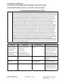
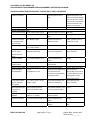
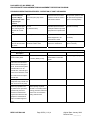
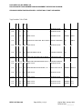
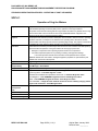
PACKAGED ICE, INC./REDDY ICE
PROCESS SAFETY MANAGEMENT/RISK MANAGEMENT PREVENTION PROGRAM
STANDARD OPERATING PROCEDURES – OPERATION OF VOGT ICE MAKERS
SOP-6.1
Operation of Vogt Ice Makers
Objective
This procedure is established to describe the Technical Operating Specifications (TOS) and to set
forth Standard Operating Procedures (SOP) for the operation of the Vogt icemakers.
All operator and technicians working with this Vogt Icemaker should be very familiar with the Vogt
Service manual that covers the VOGT P-34 A-XLOF STAINLESS STEEL equipment. This
document can be found in the Plant Engineers Office
Purpose
The purpose of the TOS is to provide a description of the ice maker, define its function, operating
conditions and limits, consequences of deviations from operating limits, describe its controls,
instrumentation and safety systems and set its operating alignment(s). The purpose of the SOP is
to establish the proper steps for startup, operation, and shut-down of the icemakers.
Concerns
Careful attention should be provided to liquid ammonia level in the Icemaker recirculator (PRR-1)
vessel and water temperature. Among the incidents we are trying to prevent are:
• Damage to compressors due to diverting liquid ammonia to the compressors
•
Low water temperature (below 45°F) resulting in freezing and equipment damage
•
Low suction pressure that will cause excessive low temperatures which requires
additional defrosts time could result in damaged equipment (expanded or ruptured tubes) and
possible loss of ammonia to atmosphere.
Department
Engineering
Operator
Responsibility
Plant Engineer - Mike Cannon
Plant Manager - Steve Waters
Equipment/Location
Vogt Icemakers IM-1 through IM-10, (Model P34 A-XLOF), Icemaker room.
Related documents
Inspection and Maintenance Records – in the Plant Engineer’s office.
System Log Book – in the Plant Engineer’s office.
Manufacturer's Installation and Operations documents – in the Plant Engineers office.
Block Diagrams – in the PSM/RMP Program document –Plant Engineers office.
P&IDs - in the PSM/RMP Program document – Plant Engineers office.
Ammonia MSDS – in Right to Know notebook located in the hall at battery charging station.
Copies of all documents – Plant Managers office.
Initial SOP
development
date
January 2002
Authorized by
Revision
No. 0
Annual Review by
REDDY ICE-DALLAS
Page SOP 6.(1-10) -1
Original Date: January 2002
Revision Date: _________
PACKAGED ICE, INC./REDDY ICE
PROCESS SAFETY MANAGEMENT/RISK MANAGEMENT PREVENTION PROGRAM
STANDARD OPERATING PROCEDURES – OPERATION OF VOGT ICE MAKERS
Technical Operating Specification (TOS)
Function
During normal operation the ammonia is fed to the icemakers through an icemaker recirculator (PRR-1), in
which the liquid ammonia is pre-chilled to approx. 12°F. The flow rate of ammonia is controlled by continuous
pressure from ammonia pumps that pump the ammonia from the icemaker recirculator through a liquid solenoid
valve (on or off) through a hand expansion valve (regulates flow), into the icemaker vessel. Vogt icemaker
water pumps recirculate water through the icemaker (evaporator tubes) upon which the ice forms. As the
icemaker rejects heat from the water the ammonia absorbs the heat, causing it to boil off. It turns into a gas
vapor at which time the gas is pulled back to the icemaker recirculator PRR-1 by various compressors
(Typically C3-C5). The compressors compress the gas vapor; it continues to the condensers (Typically (EC1EC4), in which the heat is rejected to the atmosphere through the water and airflow of the evaporative
condenser units. As the hot gas is cooled, it condenses back to a liquid; it flows through control valves back to
the icemaker recirculator vessel and is continuously recirculated. The ice making cycle is regulated by a PLC,
(Programmable Logic Controller) which controls the sequence, events and time cycles. When the ice making
cycle is complete, the vessel is pressurized to generate heat to defrost the unit. To accomplish the defrost
cycle, the water pump stops, the liquid solenoid valve (V-1-13) closes, the suction stop CK-2 valve (V-03)
closes, and the hot gas valve solenoid inlet regulator valve (V-1-18) opens. At this time pressure builds to
approximately 70 psig. The hot gas stops flowing, heat is generated, defrosting starts, the ice cutter unit starts,
and the auger system starts, the ice falls freely from the tubes during the timed defrost mode. The defrost
solenoid/regulator opens for approximately 15 seconds and allows pressure to drop in the vessel to below 50
psig before the CK-2 suction valve opens and next freeze cycle begins. The ice is augured to the blast freezer
for drying and to the rakes where it is stored. This typical cycle is repeated as required by production
requirements The vessel has a safety defrost /solenoid regulator (V-1-06) that is set to approximately 80 psig to
assure that the vessel is never over pressurized. The vessel is also protected with a dual pressure relief valve
(V-1-15), to prevent over pressurization.
Description
Capacity/Size
Operating Limits
Deviations/Consequences
Vogt Ice Makers
96.4 tons/24 hrs.
Suction pressure: 20 to
High suction pressure and
(Model P34 A-XLOF)
(1768 pounds per cycle)
30 psig
high water temperature results
Ammonia refrigerant
With setting of:
in inefficient ice production.
Stainless Steel
3.0 min. defrost
High suction can be a result of
Liquid Over Feed System 10.2 min. freeze time
compressor capacity
1 1/4“ tube size
Makeup Water temp of 55°F
problems, condenser pressure
1 1/8” Actual Ice size
Blow down water 40 gal/cycle
or water chillers effectiveness.
Low suction pressure results
in freezing up (or plugging) of
icemakers.
Water chiller
Water temperature:
Higher water temperatures
55°F – 65°F
results in loss of capacity.
Lower water temperatures and
low suction pressure could
result in an increased rate of
freezing and freeze up the
unit.
REDDY ICE-DALLAS
Page SOP 6.(1-10) -2
Original Date: January 2002
Revision Date: _________
PACKAGED ICE, INC./REDDY ICE
PROCESS SAFETY MANAGEMENT/RISK MANAGEMENT PREVENTION PROGRAM
STANDARD OPERATING PROCEDURES – OPERATION OF VOGT ICE MAKERS
Ice maker recirculator
Operating level at 30% to
High ammonia levels could
35%
result in compressor damage
due to the carryover of liquid
ammonia to the compressors.
Low ammonia levels could
result in loss of capacity.
Description
Item Number
Function
Position/Set point
Controls and Instrumentation
Suction Pressure Gauge
¼ inch Hansen (HGV1) Panel
Hot Gas Pressure Gauge ¼ inch Hansen (H7771) Panel
Pressure indicator for suction
12-20 psig
Pressure indicator for Hot
Discharge pressure.
Gas
Icemaker cycle setting
Allen Bradley System
PLC (Programmable
Controls the freeze and
Freeze cycle time 10.2 min.
defrost cycle time.
Defrost time 3.0 min.
Logic Controller)
Liquid Line Solenoid
V-1-12
Turn ammonia liquid on or off ON or OFF
1 ½” Hansen (HS4A)
(2 each) Hand Isolation
V-1-12 & V-1-16 (1 ½ Hansen)
Isolate Liquid Solenoid for
Hand angle stop vales
valves for Liquid
(AS150C) & (GS150C)
removal or maintenance
(Open or Closed)
Protects against foreign
Filtration
Solenoid valve with
strainer.
Liquid Line Strainer
1 ½” Hansen (ST200) V-1-15
debris
Liquid Line Hand
1 ½” Hansen (RS150C) V-1-15
Expansion Valve
Regulates rate of liquid
Various restriction control
ammonia flow
Liquid Line Check Valve
1 ½” Hansen (HCK4-7) V-1-14
To prevent liquid backup.
Pressure driven check valve
Defrost or by-pass
V-1-06
Opens at end of defrost cycle Solenoid open for
solenoid/regulator
RS (A4AB-ST) V-1-06
to drop pressure and
approximately 15 seconds at
prevents over pressurization
the end of defrost cycle and
of icemaker vessel.
bleed regulator is set to
approximately 80 psig
V-1-17 & V-1-20 (2 ½” angle)
Isolate Defrost Regulator for
Hand angle stop vales
Isolation valves.
removal or maintenance.
(Open or Closed)
Water temperatures will
Thermocouple wire device
Temperature indication of the 55-65°F
be displayed on
(In and Out of water chiller)
in coming (make-up) water.
(2 each) Hand Isolation
valves for defrost bypass regulator.
Panelview.
Inlet Hot Gas Regulator V-1-18
Supplies hot gas to icemaker
Solenoid
Hansen 2 ½”. (4AOS)
vessel for defrost
Hot Gas Line Strainer
1-1/2 inch Hansen (ST200) V-1-18 Protects against foreign
70 psig
Filtration
debris
Hot Gas Check Valve
REDDY ICE-DALLAS
2 inch Hubbell (R2004) V-1-23
Prevents liquid backup in hot
Pressure operated check
gas line.
valve
Page SOP 6.(1-10) -3
Original Date: January 2002
Revision Date: _________
PACKAGED ICE, INC./REDDY ICE
PROCESS SAFETY MANAGEMENT/RISK MANAGEMENT PREVENTION PROGRAM
STANDARD OPERATING PROCEDURES – OPERATION OF VOGT ICE MAKERS
Automated Suction
V-1-3
Closes suction line to allow
Gas powered operation valve
Stop Valve W/gas
5 inch RS (CK-2) stop check
pressure to build in vessel to
with pilot solenoid operation.
valve.
build heat for defrost.
(Open or Closed position)
Solenoid operated pilot
V-1-10
Solenoid opens and closes
(Opened or Closed)
valve controls gas that
½” (RS Pilot valve)
small pilot valve that provides
operated check valve
W/ pilot for gas
actuation.
gas pressure to operate CK-2
operates CK-2 check
valve
Oil Trap Drain Valve
V-1-26 (½” Hansen AT051C)
Hand valve on oil drain trap.
See SOP 7 (Oil Drain
Allows trapped oil to be
Procedure)
removed from vessel.
(2 each) Hand Isolation
valves for CK-2 Suction
V01 & V02 (5” angle)
Isolate CK-2 Stop Suction for
Hand angle stop valve.
RS Hand Isolation Valve
removal or maintenance.
(Open or Closed)
Stop Valve
Safety & Safety Systems
Item Number
Description
Function
High-pressure dual valve
V-1-21
To prevent over
pressure safety relief.
½ Hansen (H5601) 3-way
pressurization of icemaker
Position/Set point
Factory Set @ 275 psig
vessel
In the event of an ammonia
leak that reaches 200 ppm in
the air, the automated system
controller will turn on all
exhaust fans, and if 500 ppm
of ammonia is detected, it will
turn off all motors except the
exhaust fans.
Before any vessel or
component entry is made see
SOP 10 on use of Jet pump.
Before any operation of or
Before opening of system.
any maintenance procedure
See SOP 11 on Safety issues
is performed, personnel
covering protective cloths and
should have reviewed the
tools to have on hand when
Vogt Service Manual for the
dealing with ammonia.
equipment. This Manual is
kept in the Plant Engineers
Office.
REDDY ICE-DALLAS
Page SOP 6.(1-10) -4
Original Date: January 2002
Revision Date: _________
PACKAGED ICE, INC./REDDY ICE
PROCESS SAFETY MANAGEMENT/RISK MANAGEMENT PREVENTION PROGRAM
STANDARD OPERATING PROCEDURES – OPERATION OF VOGT ICE MAKERS
The Vogt Icemaker system is
equipped with a freeze up
switch, that in the event of a
freeze up, leaves the suction
valve open, turns off the
water pump and closes the
liquid line valve. The unit
remains idle for the duration
of it’s freeze cycle. This
allows the liquid level to
decrease and provide needed
space to receive an adequate
volume of hot gas needed for
a clean defrost to occur on
the next normal defrost cycle.
This should clear the unit.
The unit will then return to the
normal control cycle.
REDDY ICE-DALLAS
Page SOP 6.(1-10) -5
Original Date: January 2002
Revision Date: _________
PACKAGED ICE, INC./REDDY ICE
PROCESS SAFETY MANAGEMENT/RISK MANAGEMENT PREVENTION PROGRAM
STANDARD OPERATING PROCEDURES – OPERATION OF VOGT ICE MAKERS
Vogt Icemaker Valve Table
UNIT
Val
#
V-(1-10)
1
5"
V-(1-10)
2
5"
Type
cont Description
ANGLE VALVE FOR CK-2 GAS STOP
BW VLV.
GLOBE VALVE FOR CK-2 GAS STOP
BW VLV.
V-(1-10)
3
5"
V-(1-10)
4
V-(1-10)
Size
Function
Manuf.
Model
ISOLATION VALVE
R/S
-
ISOLATION VALVE
R/S
-
FLG GAS POWERED SUCTION STOP VALVE STOP FLOW VALVE
R/S
CK2
1/2"
FPT
ANGLE VALVE
CHARGING VALVE
HANSEN AT051H
5
1/4"
FPT
LIQUID LINE STRAINER DRAIN VALVE
DRAIN VALVE
HANSEN HGV1
V-(1-10)
6
2"
V-(1-10)
7
V-(1-10)
FLG DEFROST BY-PASS PRES. REG. W/STR. DEFROST PRESSURE
R/S
A4AB-ST
1/4"
FPT PRESSURE GAUGE, 30"-0-160#
MEASURE PRESSURE
R/S
Q6
8
1/4"
MPT GAUGE VALVE
ISOLATION VALVE
R/S
V12
V-(1-10)
9
1/2"
SW
R/S
-
V-(1-10)
10
1/2"
ANGLE VALVE
ISOLATION VALVE
PILOT SOLENOID VAL. W/STR. FOR CKFLG 2
START/STOP FLOW
R/S
S8F-ST
V-(1-10)
11
1/2"
SW
HAND EXPANSION VALVE
METERING CONTROL
R/S
-
V-(1-10)
12
1 1/2"
SW
GLOBE VALVE
ISOLATION VALVE
-
-
V-(1-10)
13
1-1/2" FLG LIQUID LINE SOLENOID VALVE W/STR.
START/STOP FLOW
-
-
V-(1-10)
14
1 1/2"
FLG LIQUID LINE CHECK VALVE
DIRECTION CONTROL
-
-
V-(1-10)
15
1 1/2"
SW
LIQUID LINE HAND EXPANSION VALVE
METERING CONTROL
-
-
V-(1-10)
16
1 1/2"
SW
ANGLE VALVE
ISOLATION VALVE
-
-
V-(1-10)
17
2 1/2"
BW
GLOBE VALVE
ISOLATION VALVE
-
-
V-(1-10)
18
2 1/2"
FLG PRESSURE REGULATOR W/STR., 2.5"
MODULATION VALVE
HANSEN HA4AS-ST
V-(1-10)
19
3/8"
FPT
ANGLE VALVE
PURGE
HANSEN H7773
V-(1-10)
20
2"
BW
GLOBE VALVE
ISOLATION VALVE
-
V-(1-10)
21
3/4"
FPT DUAL RELIEF VAL. ASSM, SET 275 PSIG OVER PRES. RELIEF
HANSEN H5601-275#
V-(1-10)
22
1/4"
FPT
ANGLE VALVE
ISOLATION VALVE
HANSEN HGV1
V-(1-10)
23
2"
FLG
CHECK VALVE
DIRECTION CONTROL
HUBBELL R2204
V-(1-10)
24
1/4"
FPT
ANGLE VALVE
ISOLATION VALVE
HANSEN H7771
V-(1-10)
25
3/8"
FPT
ANGLE VALVE
ISOLATION VALVE
HANSEN H7773
V-(1-10)
26
1/2"
FPT
ANGLE VALVE
DRAIN VALVE
HANSEN AT051H
REDDY ICE-DALLAS
Page SOP 6.(1-10) -6
-
Original Date: January 2002
Revision Date: _________
PACKAGED ICE, INC./REDDY ICE
PROCESS SAFETY MANAGEMENT/RISK MANAGEMENT PREVENTION PROGRAM
STANDARD OPERATING PROCEDURES – OPERATION OF VOGT ICE MAKERS
Standard Operating Procedure (SOP)
Task Flow
Manual start-up procedures
|
Monitor normal operations
|
Manual shut-down procedures
|
Emergency shut-down procedures
|
Operation During Power Failure
Task
Manual start-up
Step
Comment
1. Visually check the unit for lockout/ tag out devices.
procedures (following
maintenance or
emergency operations)
2. Gradually open (to full open position) the manual isolation
The suction valve or defrost valve
valves in the icemaker suction line and check for leaks.
must be opened to allow gas
pressure from the suction side to
back up into the piping so leaks
can be detected prior to opening in
the liquid feed line. If any leaks are
detected, close the valve and fix
the leaks before proceeding.
3. Gradually open (to full open position) the manual isolation
valve in the icemaker hot gas line and check for leaks.
4. Gradually open (to full open position) the manual isolation
valve in the liquid line.
5. Turn the selector switch for desired icemaker to the Auto
position.
6. Visually verify that all control valves are in the Auto
position.
7. Monitor the level in the icemaker as it fills with liquid
The level in the icemaker should
ammonia.
increase to 100 % capacity, as
any excess liquid would over feed
into the icemaker recirculator.
8. Observe icemaker through several complete cycles (freeze
and defrost) to ensure that it is functioning correctly and there
are no problems or leaks
REDDY ICE-DALLAS
Page SOP 6.(1-10) -7
Original Date: January 2002
Revision Date: _________
PACKAGED ICE, INC./REDDY ICE
PROCESS SAFETY MANAGEMENT/RISK MANAGEMENT PREVENTION PROGRAM
STANDARD OPERATING PROCEDURES – OPERATION OF VOGT ICE MAKERS
Task
Step
Comment
System monitoring
1.
during normal
determine the operational status of the refrigeration system, Engineer’s office with records kept
operations.
assess any maintenance/repair work that is underway, and
for 10+ years (excellent source of
record your shift activity.
information for apprentice
Read the logbook prior to the start of each shift to
This information is kept in the
operators)
The Vogt Icemaker log
2.
Visually inspect the icemakers through a complete
sheet should be filled out cycle, inspect the ice and size of the opening in the ice as it
Inspections are critical in the ongoing operations for safety and
once per shift. The
fall into the augers. The opening size should not exceed
performance of the plant. Note
sheets will be collected
3/16”; large hole (Shell Ice) will break up and create
unusual noises, oil stains, vibration,
by the Plant Engineer,
additional snow. Make adjustments to the freeze cycle as
etc
reviewed, signed and
required.
filed daily. The logbook
will remain on file in the
Plant Engineers Office.
Check lubrication
schedule daily for any
listed equipment due for
lubrication.
3.
Visually inspect to determine that water level in
At any time ice becomes
reservoir is adequate. Verify that water valves are
contaminated for any reason,
functioning properly. Verify that pump is adequately
contact the Plant Engineer or Plant
supplying the top reservoir and that all water diffusers are in Manager.
place. Verify there are no water leaks on icemaker.
4.
During defrost verify that hot gas regulator is not
Never put your hand in to any
exceeding 70psig and that the time it requires to reach that
auger for any reason. See Lock/Out
point matches the performance time of other ice-makers
tag out section for safety details
concerning augers
5.
Verify that defrost regulator does not bleed gas during
The regulator protects against over
defrost cycle. At the end of the defrost cycle it opens for
pressurization and is not required to
approximately 15 seconds and allow vessel pressure to
function during defrost cycles The
drop below approximately 50 psig before the CK-2 stop
regulator should be set to 80 psig.
valve opens to start the next freeze cycle.
6.
Follow lubrication schedule in the Vogt service
Hourly, visually inspect the auger
manual and record all maintenance and repair work on
system, though the blast freezer,
icemaker and refrigeration system in the logbook.
verify blast temp and ice condition
as the ice leaves and enters the
rake. Verify the rake is functioning
properly,
REDDY ICE-DALLAS
Page SOP 6.(1-10) -8
Original Date: January 2002
Revision Date: _________
PACKAGED ICE, INC./REDDY ICE
PROCESS SAFETY MANAGEMENT/RISK MANAGEMENT PREVENTION PROGRAM
STANDARD OPERATING PROCEDURES – OPERATION OF VOGT ICE MAKERS
Task
Step
Comment
Manual shutdown
The Vogt icemaker is equipped
procedures for
with isolation valves for each of
evacuating entire unit
the control valves. Using the
& opening vessel.
isolation valves, personnel can
disassemble, remove and perform
preventative maintenance on the
control valves. Evacuation of the
entire vessel would be rare.
1.
Close and tag the manual isolation valve V-1-12 in the
liquid supply line. If the icemaker can function properly, allow
the unit to continue running as usual (this allows heat from
incoming water to help boil the ammonia out quicker). If
equipment cannot function properly continue to step 2. If
equipment is allowed to continue in normal ice production
with the liquid supply closed, the liquid level will be reduced
each cycle. Monitor each cycle. The frost line should continue
to go down the vessel as the liquid is boiled out of the unit.
As the unit is depleted of liquid and the unit will no longer
produce ice, go to step 3.
2.
Otherwise, if equipment cannot continue to make ice and
vessel must be pumped out then close liquid line isolation
valve V-1-12 and hot gas inlet isolation valve V-1-17. Leave
the CK-2 check valve V-1-03 closed. Connect a hose that
has been verified to be with in date that is appropriate for
ammonia work to the service valve on the lower hot gas
manifold and connect the other end to the wet suction line of
the PRR2. With the CK-2 check valve closed, pressure
should build very slowly and help move the liquid out through
the ½ “ service valve into the accumulator PRR2. When the
liquid has been removed then continue with section 3.
3.
If a Jet pump is available see SOP 10 for proper use,
and connect a hose that is verified to be with in date and is
the appropriate type for ammonia service from the 1/2 in.
hand valve located on the vent port near the top of the unit
(V-1-19). Allow any excess ammonia vapor to be vented out
until there is no pressure reading on the suction gauge. Close
the vent port valve, remove the hose, and slowly re-open the
valve to the atmosphere to verify there is no vapor in the
vessel.
REDDY ICE-DALLAS
Page SOP 6.(1-10) -9
Original Date: January 2002
Revision Date: _________
PACKAGED ICE, INC./REDDY ICE
PROCESS SAFETY MANAGEMENT/RISK MANAGEMENT PREVENTION PROGRAM
STANDARD OPERATING PROCEDURES – OPERATION OF VOGT ICE MAKERS
Step
Task
.
4.
Comment
Follow the lockout/tag out procedure described in lockout After maintenance procedures are
/ tag out manual to lockout the appropriate disconnect.
complete, to re-starting the unit,
follow Manual start-up procedures
(following maintenance &
emergency operations) on page 7.
.
5.
At this time, work can begin on vessel repair or
maintenance procedures.
Emergency shutdown
1. In the event of a major ammonia release (e.g., pipe
Notify the Plant Engineer or Plant
procedures and
rupture) or fires, severe enough that equipment should be
Manager.
emergency operations
shut down, then use one of the (Break glass E-Stops),
located just outside of the North, East and South engine room
exit doors. This is a pull handle type E-Stop emergency shut
down switch. This will close all inlet valves, turn off all motors
and start all exhaust fans.
2. In the event of an ammonia leak that reaches 200 ppm in
the air, the automated system controller will turn on all
exhaust fans, and if 500 ppm of ammonia is detected, it will
turn off all motors except the exhaust fans.
3. In the event of an ammonia leak from a single icemaker or
Consult PSM/RMP Equipment
piping to or from an icemaker.
Summaries and SOPs for
•
Stop the flow of ammonia liquid to the individual piece
of equipment by closing the valve in the liquid supply
additional procedures to follow
for these units.
line (or stopping the appropriate pump);
•
Turn on the exhaust fans in the area;
•
Leave the valves in the suction lines open to lower the
pressure on the equipment.
REDDY ICE-DALLAS
4. Start the engine room ventilation fans for all leaks in or
There are visual and audible
around the engine room. The switches to manually start the
alarms for the ammonia detectors
ventilation fans are located just outside each of the outside
in multiple locations throughout
doors into the engine room and in the Panelview.
the facility.
Page SOP 6.(1-10) -10
Original Date: January 2002
Revision Date: _________
PACKAGED ICE, INC./REDDY ICE
PROCESS SAFETY MANAGEMENT/RISK MANAGEMENT PREVENTION PROGRAM
STANDARD OPERATING PROCEDURES – OPERATION OF VOGT ICE MAKERS
5. For compressor, evaporator, condenser, recirculator and
Read and be familiar with all
other plant equipment problems, or emergencies concerning
equipment document, service
other equipment, see the associated SOP that covers the
manual and safety bulletins
operation of that equipment.
associated with all equipment in
the plant operation. Be prepared
prior to operating the equipment.
Be knowledgeable about
procedures before you need them.
Do your part to develop a safe,
clean and efficient operation.
6. To re-start follow Manual start-up procedures (following
maintenance & emergency operations) found on page 7 of
this SOP.
Step
Task
Operations during a
1.
power failure
period close the main liquid ammonia feed valve (King valve)
Comment
If information is obtained that power will be off for a long
which is located outside the engine room at the controlled
pressure receiver.
2.
Place each compressor start selection switch in the
“OFF” position.
3.
Monitor the system pressures until power returns.
When power is restored, the
evaporative condenser fans and
cooling water pumps should start
automatically as appropriate
pressure set points are reached.
4.
To restart the plant use the procedure on page 7 of this
SOP; for Manual start-up procedures (following
maintenance or emergency operations).
REDDY ICE-DALLAS
Page SOP 6.(1-10) -11
Original Date: January 2002
Revision Date: _________
PACKAGED ICE, INC./REDDY ICE
PROCESS SAFETY MANAGEMENT/RISK MANAGEMENT PREVENTION PROGRAM
STANDARD OPERATING PROCEDURES – OPERATION OF VOGT ICE MAKERS
REDDY ICE-DALLAS
Page SOP
Original Date: January 2002
Revision Date: _________