1
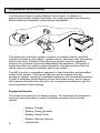
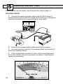
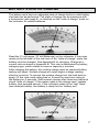
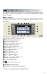
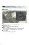
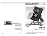
Test Equipment Auto Meter Products Inc. 413 West Elm Street Sycamore, IL 60178 Toll Free (866) 883-TEST (8378) Fax (815)-895-6786 www.autometer.com 20 2650-165X-10 Rev. H � SB-3 Battery Load Tester Instruction Manual Simplified Check Program for Charging Systems The SB-3 is a variable load battery tester that provides a simplified check for the alternator and starter. CONGRATULATIONS You have purchased a quality Battery/Circuit tester. In addition to performing accurate battery load tests, this tester provides non-inductive starter-draw and alternator output testing capabilities. The automotive electrical system consists of a battery, starter, solenoid (usually mounted on the starter), ignition switch, alternator with connecting cables and wires. All parts of the electrical system must be operating properly for a vehicle to provide dependable transportation. Whenever a component fails, the whole system should be checked to insure that the failure was not caused by another part of the system. The SB-3 model is a simplified approach to test the battery and simplified check of the system. This insures that you will be making only the necessary repairs, resulting in satisfied customers and increased business. To gain a complete understanding of how this tester works, and to derive the maximum benefits from this unit, we recommend reading through the entire instruction before testing. Equipment Needed This tester is a basic tool for battery testing. The following test equipment items are recommended in order to facilitate complete and accurate results. • Battery Charger • Battery Clamp Spreader • Battery Clamp Puller • Battery Terminal Cleaner • Hydrometer LIMITED WARRANTY (12 Months from date of purchase) Auto Meter warrants to the consumer that this product will be free from defects in material or workmanship for a period of twelve (12) months from the date of the original purchase (except for carbons and leads which are covered for 90 days). Products that fail within this 12-month warranty period will be repaired or replaced at Auto Meters option to the consumer, when determined by Auto Meter that the product failed due to defects in material or workmanship. This warranty is limited to the repair or replacement of parts in the tester and the necessary labor by Auto Meter to affect the repair or replacement of the tester. In no event shall this warranty exceed the original purchase price of the tester, nor shall Auto Meter be responsible for special, incidental or consequential damages or costs incurred due to the failure of this product. Breaking the meter seal, improper use, accident, water damage, abuse, unauthorized repairs or alterations voids the warranty. Tester manufacturer disclaims any liability for consequential damages due to breach of any written or implied warranty on its tester. 19 B APPENDIX BATTERY CHARGING GUIDE (6 and 12 Volt Batteries) Recommended charging rate and time for fully discharged batteries. Partially discharged batteries will require less charging time. BATTERY CATEGORY (RESERVE CAPACITY MINUTES) 80 minutes or less CHARGE BATTERY At either rate and time shown 14 hrs. at 5 Amps 7 hrs. at 10 Amps 80 to l25 minutes 20 hrs. at 5 Amps 10 hrs. at 10 Amps 125 to 170 minutes 28 hrs. at 5 Amps 14 hrs. at 10 Amps 170 to 250 minutes 42 hrs. at 5 Amps 21 hrs. at 10 Amps Above 250 minutes 33 hrs. at 10 Amps CAUTION Exceeding the recommended charging rates can damage the battery plates and generate potentially explosive gases. BATTERY VOLTAGE CHART ESTIMATED ELECTROLYTE TEMPERATURE 18 MINIMUM REQUIRED VOLTAGE UNDER 15 SEC. LOAD 6 VOLT 12 VOLT 70° F or above 60° F 50° F 4.8 4.75 4.7 9.6 9.5 9.4 40° F 30° F 20° F 4.65 4.6 4.55 9.3 9.2 9.1 10° F 0° F 4.5 4.25 8.9 8.5 TABLE OF CONTENTS The Charging System-------------------------------------------------2 Specifications------------------------------------------------------------3 Safety----------------------------------------------------------------------4 Cause of Battery Failure----------------------------------------------4 Battery Check and Visual Inspection------------------------------5 Preliminary Notes-------------------------------------------------------6 Battery State of Charge-----------------------------------------------7 Hydrometer Method----------------------------------------------------8 Battery Load Test-------------------------------------------------------9 Starter Draw Test-------------------------------------------------10-11 Alternator Test-----------------------------------------------------12-13 Starter Circuit Test------------------------------------------------14-15 Appendix A Service Information---------------------------------------- 16 Appendix B Battery Charging Guide---------------------------------- 18 Battery Voltage Chart------------------------------------- 18 Warranty---------------------------------------------------------------- 19 Contact Information-------------------------------------------------- 20 SPECIFICATIONS Carbon Pile Volt Meter Amp Meter Load Knob Load Clamps 12 volt 500 Amp capacity Accurate 8-16 Volt scale 0-500 Amp Scale - Precise color coded, pass/fail indication Variable load with automatic load release 500 Amp rating with vinyl coated red and black handles and insulated jaws Load Leads 5 ft. 2 gauge coax cable with internal 18 gauge conductor Dimensions 10.5” x 9” x 4” metal case Shipping Weight 12 lbs. SAFETY Carefully read all operating instructions before using the tester Wear eye protection when working around batteries. Be sure each test is completed before removing load clamps to prevent arching and potential explosion from battery gasses. Never remove load clamps while testing. Keep sparks, flames, or cigarettes away from batteries. Keep hair, hands, and clothing as well as tester leads and cords away from moving blades and belts. Provide adequate ventilation to remove car exhaust. In extremely cold temperatures, check for frozen electrolytic fluid before applying load. Do not attempt to Load Test or charge a battery under 20 degrees. Allow the battery to warm to room temperature before testing or charging. Warning! Never attach the unit to a battery that is connected to any other tester or charging unit. Damage may result. CAUSE OF BATTERY FAILURE Incorrect Application: Wrong size battery may have inadequate cold cranking rating for original vehicle specifications. Incorrect Installation: Loose battery hold-downs cause excessive vibration, which can result in damage to the plates. Improper Maintenance: Low electrolytic fluid and corrosion on battery connections can greatly reduce battery life and affect battery performance. Age of Battery: If the date code on the battery indicates it is fairly old, the failure may be caused by natural causes. Overcharging: Overcharging caused by a high voltage regulator setting or incorrect battery charging can cause excessive gassing, heat and water loss. Undercharging: Undercharging caused by a faulty charging system or low voltage regulation can cause lead sulfate to gradually build up and crystallize on the plates greatly reducing the battery’s capacity and ability to be recharged. Cardboard load holder for shipping In the event your tester needs to be returned to Auto Meter for Service, it must be properly packaged and protected to avoid damage during shipment. Failure to follow these steps will allow the carbon disks to rattle freely during shipment and cause breakage. Before packing the tester for return shipment, turn load knob fully clockwise until it stops, hold in position and slip a snugly fit cardboard holder over the load knob. This will then rest against the cables and prevent the load knob from turning back. The load knob holder must be 3-1/2" by 9-3/4" with a 2-3/16" hole cut out in the center and slightly off-set (copy and use template below). Please use a thick enough piece of cardboard, preferably corrugated, to prevent bending and slippage of the load knob. You can also use a heavy rubber band that wraps around the load knob while tight then around the leads and back around the load knob again. 17 A APPENDIX: SERVICE INFORMATION Warranty claims to Auto Meter must be transportation prepaid and accompanied by dated proof of purchase. This warranty applies only to the original purchaser and is non-transferable. Damage incurred during return shipment is not covered under this warranty. It is the responsibility of the shipper (customer returning tester) to package the tester properly to prevent damage during return shipment. Repair costs for such damages will be charged back to shipper (customer returning tester). Before packing tester for return shipment, tighten load knob and secure to prevent breakage of carbon discs during shipment due to rattling. Also protect the meters and add plenty of over-pack cushioning such as crumpled-up newspaper. For Service Address See Back Cover 16 BATTERY INSPECTION Valid automotive electrical system testing depends on all the components being in good operating condition. In addition, the battery MUST have sufficient charge for testing. Carefully perform the following before attempting any electrical diagnosis. VISUAL CHECK Inspect Belts for cracks, glazed surface and fraying. Tighten loose belts. Inspect Battery for terminal corrosion, loose or broken posts, cracks in the case, loose hold-downs, low electrolyte level, moisture, and dirt around the terminals. Inspect Starting System. Check starter, solenoid, and regulator for loose connections, loose mounts and frayed or cracked wires. Important Note: A defective battery must be replaced before proceeding. PRELIMINARY NOTES 1. MOISTURE If tester has not been used recently, moisture may have condensed between carbon pile discs. This will cause the tester to emit some steam during first or second load application. This is normal and is not a malfunction of the tester. (Do not confuse this with an overloading of the tester.) 2. BATTERY RATING 3. BATTERY TEMP. The temperature of the electrolyte Batteries are rated in Cold Crank and plates inside a battery affects Amps or Amp-Hours. This tester its output capability. As a result, it uses a stabilized variable load carbon pile that allows each battery is necessary for the serviceman to be tested at its proper rating. For to closely estimate the battery’s batteries rated in Cold Crank Amps, temperature when testing. This tester has temperature ranges ½ the Cold Crank rating load is applied using the Amps scale on the clearly shown on Pass/Fail bands, meter. For Amp-Hour rated batteries, so that accurate test results can be a load three times the Amp-Hour rat obtained easily. ing is applied using the Amp scale. 4. TESTER HOOKUP Take special care when connecting to side terminal batteries. If necessary, use a side post adapter to prevent thread damage. When testing dual post batteries always check the post to which the system is attached. If a load test is made from a post connection and the alternator is mounted to side terminals a battery load test can be completed, but a continuity problem may still be in the side terminals when testing the alternator. GROUND CIRCUIT 5. To check the ground circuit, connect the RED clamp directly to the starter casing (this may require chipping paint to make a good connection), and the BLACK clamp to the battery negative terminal as shown in example below. BLACK RED 6. While cranking the engine, observe the voltmeter. The voltage drop should not exceed 0.3 volts. The total of the two tests should not exceed 0.8 volts. Example: If positive reads .5 and negative reads .3 the total is .8 Volts. Example: 0.5 volts on the positive circuit + 0.3 volts on the ground circuit .8 total system voltage drop 15 5 STARTER CIRCUIT TEST Disable ignition as indicated in the Starter-Draw Test on page 10. POSITIVE CIRCUIT 1. Connect the tester as shown below with the RED clamp to battery positive and the BLACK clamp to the terminal on the starter, which is connected to the solenoid directly or by cable. RED BLACK 2. Observe the voltage reading while cranking the engine. 3. On most light duty vehicles, the reading should not exceed 0.5 volts (see example below). 4. If the voltage drop exceeds 0.5 volts, check the voltage drop across the cables, solenoid, and each connection. Repair and/or replace as necessary. 14 BATTERY STATE OF CHARGE The battery must have an adequate state of charge before a valid battery load test can be performed. The state of charge can be measured with a hydrometer (see page 8), or checked on the “state of charge” scale on the voltmeter for sealed batteries. Read the 12 volt range (12 Volt Batteries) on the voltmeter, If the meter reads on the left side, in the red zone of the “state of charge” scale, the battery must be charged. See Appendix B for charging. Charge at a current rate as shown in Appendix B. This rate is determined by battery category type, which relates to reserve capacity in minutes. After charging the battery, the surface charge must be removed before testing can begin. Surface charge will cause higher voltage reading which is incorrect. To remove the surface charge turn the load knob to apply 1/2 the cold crank rating load or 3 times the amp-hour rating to the battery for 5 seconds. Wait several minutes after removing load and check “state of charge”. If the meter reads in the charge zone, replace battery (see example above). If the voltmeter reads in the “test” band (see example below), the battery is ready for the “battery test”. HYDROMETER METHOD Check the electrolyte specific gravity with a hydrometer. If the specific gravity measures between 1.100 and 1.220, the battery must be recharged. If the specific gravity is between 1.225 and 1.265, the battery is ok to test. If the hydrometer has a temperature correction chart, be sure to adjust the reading for the battery’s temperature. Variance of specific gravity between cells is not significant on discharged batteries (batteries with specific gravities below 1.225). However, if there is a variance of 50 points (0.050) in a battery whose specific gravity is 1225 or more, that battery is defective. NOTE: A defective battery must be replaced before proceeding with any electrical system tests. Solutions: • If alternator reads in the low end of the OK range, it is working fine. For people driving short distances, however, the battery may not charge fast enough, causing the battery to run down slowly. A higher amperage alternator may be necessary to insure faster charging. • Some shorting or grounding may occur and slowly drain battery. Use a low range ammeter and check to see that no current flows from the battery with all accessories and engine turned off (including clocks). If current is flowing, locate cause and repair. Look for such things as trunk, hood, ashtray and glove compartment lights, bad switches, etc. • Ammeters installed after vehicle manufacture may not have sufficient wire gauge to carry current without causing a voltage drop. This can reduce battery-charging rate, Measure the voltage drop from battery positive to alternator output terminal. If the drop is greater than 0.5 volts, and all connections are clean and tight replace all wire between the two points with wire that is one gauge heavier. • Aftermarket accessories may add enough load to the charging system to exceed alternator capacity (i.e., stereos, telephones, defoggers, etc.). Replace alternator with one of higher capacity. Dual Battery System • When load testing check each battery separately with cables disconnected, so a problem with one battery is not masked by another battery. • Charging system should be checked with both batteries connected. • Accessories may be connected to one or both batteries. Be alert to their wiring differences in testing for problems. 13 4 ALTERNATOR TEST To charge a battery, the alternator must produce a voltage higher than the battery voltage to cause current to flow into it. Therefore, the voltage must rise to the “OK” test zone of the ALT. & REG. TEST band. Before testing, run the vehicles engine at fast idle with all the accessories off for at least 5 mins. to recharge the battery and to stabilize the temperature of the alternator. (Remember, the following tests are valid only if the battery has passed the Battery Load Test (See page 9). For the following tests, continue running the engine at fast idle). The battery is recharged when the voltmeter reading has stabilized at its highest reading. Observe the voltmeter reading in the “ALT. & REG. TEST” band: REGULATION: 1. If in HI zone (See Figure A): Apply a normal accessory load, such as lights, heater and wipers. Fig. A 2. If the reading drops more than 0.5 volts, there may be a wiring and/ or connector problem between the alternator output and battery positive (+). If the alternator is producing adequate charge, and the pointer stays in the OK band, the charging system is OK, and the test is complete (see Fig. B). 3. If the meter is in the low band replace the alternator (see Fig. C) OUTPUT: Fig. B 12 Fig. C 4. Apply a Load upon the battery until the Volts drop to 12.6. At that moment, read Amps and add the key draw amps (10-20 amps). The Load Amps + Key Draw Amps = Total alternator output. Troubleshooting Alternator (Hypothetical Situation) Problem: Customer returns continually because his battery keeps running down, but all bat Battery and alternator tests pass. 1 BATTERY LOAD TEST 1. Turn load knob to apply a load equal to 1/2 the Cold Crank rating or 3 times the Amp-Hour rating for 15 seconds. (See Battery Rating Page 6) 2. Hold proper load for 15 seconds observe the voltage reading, and then immediately decrease the load until the fan stops and the ammeter reads zero. 3. If the Volt meter reads in the green zone for the approximate battery temperature, pass the battery (see example above). If the Volt meter reads in the red zone, replace the battery (see example below). Use the battery Voltage Chart in Appendix B on page 18 to compare test results. WARNING Be sure load is off before attaching or removing load clamps to prevent arcing and potential explosion from battery gases. Always shield eyes and keep sparks, flames or cigarettes away from batteries when testing. 2 STARTER DRAW TEST For proper starter functioning, it is important that all related connections are clean and tight, and that the cable and its insulation are in good condition. On all starter circuit tests, disable ignition circuit by one of the • following methods: • STD. IGNITION- (Points & Cond.): Ground coil output. • ELEC. IGNITION- (Module): Disconnect 12V power supply. • DIESEL: Disconnect 12V power supply to fuel shut-off solenoid. The battery voltage will drop as it is loaded by the starter or with the tester. • CHECKING THE VOLTAGE USING THE STARTER: Crank engine and observe the voltmeter reading. Do not crank engine over 7 seconds at one time to eliminate possible damage to starter windings. LOAD VOLTS SAME AS STARTER VOLTS • CHECKING THE VOLTAGE USING THE TESTER: The tester is used as a load to simulate the starter load. This is done by applying a load until the voltage drops to the same voltage observed while cranking the engine. Thus, the tester load amps indicated in the black 0-500 scale are the same as the starter amp load. Read amps indicated on the scale while load is applied (see example below). This is the starter-draw current. Compare amp draw to manufacturer specifications. 10 STARTER DRAW TEST CONT. Example: 1. With ignition disabled crank vehicle and observe lowest volt reading. For this example, we’ll say it reads 11 volts. 2. Apply a load with the Load knob until voltmeter reads 11 volts (see example page 10). Quickly read the ammeter. In this case it reads 240 amps. Remove the load (knob turned fully counterclockwise). 3. We now know the starter draw is 240 amps and that it is generally within specifications for a V8 gasoline engine (see Maximum Amps chart on page 11). Maximum Amps If manufacturer’s specifications are not available, the chart below can be used as a general guideline for light duty engines and starters. Amounts are in Amps. Keep in mind that the SB-3 reads up to 500 Amps. If the manufacture’s specifications and in the case of 8 Cyl Dsl below exceed 500 Amps the SB-3 will not test the starter draw. 11