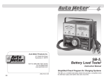
1
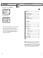
�
Test Equipment
Auto Meter Products Inc.
413 West Elm Street
Sycamore, IL 60178
Service (815)-899-0801
Toll Free (866)-883-TEST (8378)
www.autometer.com/test
24
2650-1383-00
5/8/13
BVA-300
Operator’s Manual
Hand Held-Accuracy with a 40 Amp Load
The BVA-300 is the a hand-held tester that is the auto industry’s answer
to portability in a professionally accurate battery load tester and system
analyzer.
CONGRATULATIONS!
You have purchased one of Auto Meter's hand-held
Battery, Starting and Charging System Analyzers. It is
designed to test each component of a vehicle's electrical system with
speed and accuracy. If you should have any questions about your tester,
testing procedures, or service see the last page of this booklet for contact
information.
BVA-300
Load Test Capacity..................40 Amp
Battery Sizes............................100-1600 CCA
Digital Display .........................1" x 2.5" - 4 line x 16 character
Volt Ranges..............................Digital 0-30
Cooling.....................................Heat Sink Ventilation
Leads.......................................Load Amp-2 1/2 ft., 16 Gauge
Size..........................................3 3/4" x 6 3/4" x 1"
Memory....................................stores the last 100 tests
Internal Battery.........................9 Volt Alkaline
Optional PR-12........................Infrared printer
Optional AC-12 .......................PC Interface adapter cord
Optional AC-24J.......................Carrying case only
Optional AC-32........................Serial Port to USB adapter
Optional AC-62........................AMP Link Data Download PC software
Weight......................................1.34 lbs.
What to Expect from the BVA-300:
Immediately determine battery condition and perform a complete
starting and charging system analysis. The BVA-300 is a portable fullfeatured menu-driven battery tester and system analyzer that provides
quick, professional load results using Auto Meter's Pulsed Load. The
BVA-300 is user friendly. It tells you what to do. The stator-diode test
automatically indicates open or shorted stator-diodes. It is professionally
accurate. Detailed test results are LCD displayed after each test and can
be reviewed and/or printed from memory.
2
LIMITED WARRANTY
12 MONTHS FROM DATE OF PURCHASECABLES 90 DAYS
The manufacturer warrants to the consumer that this product will
be free from defects in material or workmanship for a period of
twelve (12) months from the date of original purchase.
Products that fail within this 12 month warranty period will
be repaired or replaced at the manufacturer's option to the
consumer, when determined by the manufacturer that the product
failed due to defects in material or workmanship. This warranty
is limited to the repair or replacement of parts and the necessary
labor by the manufacturer to effect the repair or replacement of
the product. In no event shall the manufacturer be responsible
for special, incidental or consequential damages or costs incurred
due to the failure of this product.
Improper use, accident, water damage, abuse, unauthorized
repairs or alterations voids this warranty. The manufacturer
disclaims any liability or consequential damages due to breach of
any written or implied warranty on its test equipment.
WARRANTY AND SERVICE INFORMATION
Warranty claims to the manufacturer's service department
must be transportation prepaid and accompanied by a dated
proof of purchase. This warranty applies only to the original
purchaser and is non-transferable. Freight damage incurred
during return shipments is not covered under this warranty. It
is the responsibility of the shipper (the customer returning the
Test Equipment) to package the tester properly to prevent any
damage during return shipment. Repair costs for such damages
will be charged back to shipper (customer returning the Test
Equipment). Protect the product by shipping in original carton
or add plenty of over-pack cushioning such as crumpled up
newspaper.
23
PC INTERFACE
From the Main Menu scroll down to DOWNLOAD
REVIEW/PRINT
VOLT METER
>DOWNLOAD
SETUP
The following will be displayed
CONNECT TESTER
TO A PC RUNNING
DATA SOFTWARE
'N' TO CANCEL
Using Auto Meter's optional adapter cord AC-12 insert the stereo
plug into the jack on the BVA-300 and then plug the serial
adapter into a free serial port on the rear of your computer or
connect to AC-32 serial port to USB adapter. Follow the
instructions of the AC-62 AMP Link Data Download software to
retrieve data from the BVA-300.
TABLE OF CONTENTS
Page
Specifications--------------------------------------------------------2
Safety------------------------------------------------------------------4
Cause of Battery Failure------------------------------------------4
Inspection and Visual Check-------------------------------------5
Controls and Functions--------------------------------------------6
Maintenance---------------------------------------------------------7
Clamp Replacement-----------------------------------------------7
Internal Battery Replacement------------------------------------7
Test Sections
1. Hook Up-----------------------------------------------------------8
2. Battery Load Test------------------------------------------9 -11
3. Starter Draw Test-----------------------------------------12 -15
4. Alternator Test----------------------------------------------16-17
5. Other Menu Items
Review Tests-------------------------------------------- 18
About------------------------------------------------------ 18
Printing Test Results---------------------------------- 19
Voltmeter------------------------------------------------- 20
Setup------------------------------------------------------ 20
PC Interface--------------------------------------------- 22
Warranty Information--------------------------------------------- 23
Contact Information---------------------------------------------- 24
Note: The BVA-300 load tests 6 volt and 12 volt batteries and
tests 12 Volt and 24 Volt starting and charging systems. The
following examples illustrated are for a 12 Volt system. The BVA300 automatically identifies the appropriate voltage and displays
the menu selection and instructions needed for that system.
22
3
SAFETY
Carefully read all operating instructions before
using the BVA-300
Wear proper protection when working around batteries.
Be sure each test is complete before removing
load clamps to prevent arcing and potential
explosion from battery gases. Keep sparks
flames, or cigarettes away from batteries.
Keep hair, hands, and clothing as well as tester
leads and cords away from moving blades and
belts.
Provide adequate ventilation to remove car exhaust.
In extremely cold temperatures, check for frozen
electrolytic fluid before applying load. Do not attempt
to Load Test or charge a battery under 20 degrees. Allow the battery to warm to room
temperature before testing or charging.
Warning! Never attach the BVA-300 to a battery that is connected to any other tester
or charging unit. Damage may result.
SETUP (cont.)
>SET DEFAULT
RATING: CCA
USE +/'Y' TO SELECT
>SET DEFAULT CCA
AS: 600
USE+/'Y' TO SELECT
Incorrect Application: Wrong size battery may have inadequate cold cranking Amp
rating for original vehicle specifications.
Incorrect Installation: Loose battery hold-downs cause excessive vibration, which
can result in damage to the battery plates.
Improper Maintenance: Low electrolytic fluid and corrosion on battery connections
can greatly reduce battery life and affect battery performance.
Age of Battery: If the date code on the battery indicates it is old, the failure may be
caused by natural causes.
Overcharging: Overcharging caused by a high voltage regulator setting or incorrect
battery charging can cause excessive gassing, heat and water loss.
Undercharging: Undercharging caused by a faulty charging system or low voltage
regulation can cause lead sulfate to gradually build up and crystallize on the plates
greatly reducing the battery’s capacity and ability to be charged.
4
You can also select the default rating
to be the last entered CCA value or a
particular amount such as 600 CCA.
DO YOU WANT TO
DISPLAY MEASURED
BATTERY CAPACITY
'N' OR 'Y'
If 'Y' is chosen, the measured battery
capacity will be displayed on the
battery test result screen and print out.
If 'N' is chosen no measured battery
capacity will be displayed or printed.
USE TEST RESULT
NEAR END OF LIFE
USE+/'Y' TO SELECT
To toggle battery test results between
"GOOD" or "BAD" only and "NEAR
END OF LIFE", use + or - to change
setting then use 'Y' to select.
PRINTOUT OPTION
AC-14/PR-12
USE +/'Y' TO SELECT
CAUSE OF BATTERY FAILURE
Select the rating from
CCA, MCA, CA, AH, EN.
DO YOU WANT TO
ENTER STORE INFO
'N' OR 'Y'
To print to an Auto Meter stand alone IR
printer choose "AC-14/PR-12". To print
to the Auto Meter high speed PR-16
printer using the Auto Meter XTC-160
charger/tester and IR-1 printer interface
choose "XTC-160/PR-16. To print to
a network printer using the POSI-160
choose "POSI-160".
Press 'Y' to enter or change the store
address for use on print outs or 'N' to
continue.
Entry Hints
Note: Address one & two and city have a max of 23 characters.
To change the text or number press the (+)
more text keep pressing 'Y' until the cursor
or (-) keys. If you press 'N' at the beginning
is on a blank space at the end of the lines
of the screen, no changes will be made. To
of text. Pressing 'N' moves back the cursor
make changes, use the (+) and (-) keys then
position back one character. Pressing Print
press 'Y' to save the change. The cursor will
saves the text up to the cursor position. Any
then go to the next character or number. If
text after is deleted.
you are done making changes but there is
21
INSPECTION
VOLT METER
Scroll Down to Volt Meter then select Volt Meter by pressing Y
>VOLT METER
DOWNLOAD
SETUP
ABOUT
Press (Y Enter)
Valid automotive electrical system testing depends on
all the components being in good operating condition.
In addition, the battery MUST have sufficient charge for
testing. Carefully perform the following before attempting
any electrical diagnosis.
VISUAL CHECK
Inspect Belts and Pulleys for cracks, glazed
-VOLT METERVOLTS: 12.24V
RIPPLE 00.0mV
Note: If the car is running and the
clamps are attached to the battery
a high ripple (over 50mV) indicates
bad diodes in the alternator.
surface and fraying. Tighten loose belts.
Inspect Battery for
terminal corrosion,
loose or broken posts,
cracks in the case,
loose hold-downs, low
electrolyte level, moisture and dirt around the
terminals.
SETUP
Scroll Down to Setup, Select setup by pressing Y
VOLT METER
DOWNLOAD
>SETUP
ABOUT
>SET LANGUAGE:
ENGLISH
USE +/'Y' TO SELECT
Choose between English, Spanish,
or French using the + and - keys to
change the language. Press 'Y' to
select.
Inspect Starting System. Check starter, solenoid, and regulator for
loose connections, loose mounts and frayed or cracked wires.
Important Note: A known defective battery must be replaced before
>SET TEMPERATURE
SCALE: F
USE +/'Y' TO SELECT
20
proceeding.
Select the temperature in Fahrenheit
or Centigrade.
5
CONTROLS AND FUNCTIONS
PRINTING TEST RESULTS
LCD:
Displays menus and test results.
KEYS:
When each key is pressed, a beep
sounds to assure contact has been
made.
On/Off Key:
This is the manual on/off key.
AUTO METER
BVA-300
TESTER/ANALYZER
‘Y’ FOR MENU
Point the BVA-300 in the direction of the PR-12 printer
with the printer’s IR receiver pointed in the direction of the
BVA-300. Press (Print). You should be within 15 ft of the printer. Wait
for the screen to clear before moving the BVA-300. It takes a moment
to send all the test data. The BVA-300 also operates the AC-14 printer
installed in Auto Meter’s XTC-160 tester/charger or BVA-2100 heavy-duty
tester/analyzer or Auto Meter's PR-16 Printer when used with a XTC-160
and IR-1 Printer Interface.
Make sure the Infrared Printer is
properly set up.
After a test is made with the
BVA-300 make sure the results
are displayed on the LCD.
Point the BVA-300 in the
direction of the Infrared Printer
(within 15 ft.)
Press the <Print> key and the
test results will be printed.
Depending upon the test made
the printer will sometimes yield
more information than the LCD.
Y Enter Key:
This key selects the next menu, the
cursor line item and answers ‘yes’ to
a test progression.
+Up Key:
This key moves the cursor up in
order to select a menu line item and
increments certain displayed values.
-Down Arrow Key:
This key moves the cursor down in order to
select a menu line and decrements certain
displayed values.
N Esc Key:
This key cancels a test or progression. It also returns to the previous
menu.
Print Key:
Point the BVA-300 infrared print light towards the Optional PR-12 infrared
printer receiver and press the print key. Test results will be printed.
Infrared Print Light:
When the print button is pressed
infrared data will be transmitted
to the printer when pointed in
the approximate direction of the
printer (up to 40 ft.).
PC Download Jack:
Adapter cord AC-12 can be
inserted.
6
19
5
OTHER MENU ITEMS
CLAMP MAINTENANCE:
REVIEW TESTS
CHECK OFTEN FOR LOOSE JAWS
OR DAMAGED INTERNAL INSULATOR
Scroll Down to Review/Print
>REVIEW/PRINT
VOLT METER
DOWNLOAD
SETUP
Press (Y Enter) to select
Review/Print.
The last test will be displayed.
#44 RV ALTER.
VOLT REG PASSED
DIODES
PASSED
OUTPUT
PASSED
BVA-300
VERSION 3.0
SER #: 17533
COPYRIGHT 2013
18
Both jaws of each clamp must firmly engage the battery terminal
The wire soldered to the copper insert jaw must be insulated
from the other wire soldered to the opposite handle. This
insulation is required so than one can read the Amps and the
other can read the Volts. Damaged clamps or loose wires will
affect readings. Make sure the copper jaw insert is properly
insulated from the clamp and the clamps are clean and in
good repair.
Press (N Esc.) to select
previous test. Press (+Up)
or (-Down) key to select the
desired test.
Over time the battery clamps will need to be replaced if any of the
following are indicated:
Scroll down to about.
Press Y to select.
CLAMP and BATTERY REPLACEMENT
ABOUT SCREEN
VOLT METER
DOWNLOAD
SETUP
>ABOUT
MAINTENANCE
The about screen shows the
model number. Firmware
revision and the tester
serial number.
Press any key to go back to
the menu.
CCA values seem extreme.
If there is continuity between the copper insert and the clamps.
If there is excessive damage or corrosion to the cables or
clamps.
Remove the screws from the back cover.
Separate top and bottom cover and open like a book leaving the
ribbon in contact with the PC board that will remain with the back
cover.
CLAMPS: Remove the cables and strain relief. With the new
load clamp leads pointing down; insert the new strain relief into
the back cover. Make sure the red clamp wires are attached to
the left two screws of the green screw terminal (labeled POS)
and the black clamp wires are connected to the right two screws
(labeled NEG). It does not matter if either of the two red clamp
wires is switched. The same applies to the two black clamp
wires. Just make sure the red clamp wires are to the left (POS)
and the black clamp wires are to the right. (NEG)
BATTERY: Remove the battery and replace with a 9 Volt battery.
Match the (+) on the new battery with the (+) on the PC board.
Reverse the procedure to assemble the unit.
7
1
HOOK UP
ALTERNATOR TEST RESULTS
Press the On/Off button: Connect the clamps as instructed on the LCD.
AUTO METER
BVA-300
TESTER/ANALYZER
'Y' FOR MENU
>ENTER BATTERY
TEMP:
70F
USE +/'Y' TO CONTINUE
Enter the approximate battery
temperature in degrees Fahrenheit or Celsius (seen note) then press (Y
Enter).
Note: Go to the setup to change temp scale to Celsius. The temperature
request only appears once for each battery tested. If the clamps are
disconnected you will be prompted again to begin a new battery test.
Test result will appear. The following are examples.
#3 12V ALTER.
VOLT REG PASSED
DIODES
PASSED
OUTPUT
PASSED
Alternator passed all tests.
#3 12V ALTER.
VOLT REG PASSED
DIODES
PASSED
OUTPUT
FAILED
Alternator output is too low.
#3 12V ALTER.
VOLT REG PASSED
DIODES
FAILED
‘Y’ TO CONTINUE
The alternator diodes are
bad.
#3 12V ALTER.
VOLT REG FAILED
DIODES
PASSED
‘Y’ TO CONTINUE
The alternator voltage
regulator has failed and the
voltage is either too high or
too low.
Note! Take special care when connecting to battery side terminals. If
necessary use a side post adapter to prevent thread damage. When
testing dual post batteries always connect load clamps to the post to
which the system is attached.
CONNECTION ERRORS
If the clamps are reversed the Reversed Connection screen
will flash.
If one or both of the clamps are not in complete contact
(including both jaws) CHECK CONNECTIONS! will flash.
8
17
4
ALTERNATOR TEST
This test measures the output of the charging systems under load conditions. This information provides the basis for further charging system tests.
It also detects the presence of an open or shorted diode that causes an
output loss of several amps and can cause the failure of other diodes.
Symptomatic Check before Proceeding:
Battery should be in good condition and charged before testing the Charging System.
Check warning light indications.
Check belt condition and tension.
Check all cables and connections.
Check the battery for corrosion and dirty terminals.
Does the battery have a low state of charge? (See section 2 and 3)
Make sure all electrical items are off.
Check for Alternator noise.
BATTERY TEST
STARTER TEST
>ALTERNATOR TEST
REVIEW/PRINT
ALLOW VOLTAGE
TO STABILIZE
14.43
Use the (+Up) and (-Down) arrows to
move cursor to the desired test.
The BVA-300 will allow the voltage
to stabilize before starting the test
bar at the bottom of the screen that
shows the test progress. Be patient,
it can take up to 30 seconds for the
voltage to stabilize.
Allow the alternator test to finish.
TESTING ALTERNATOR
PLEASE WAIT…
Bar at the bottom of the screen will
show the tests progress.
2
BATTERY TEST
>BATTERY TEST
STARTER TEST
ALTERNATOR TEST
REVIEW/PRINT
If any of the tests (battery test or starter test, or alternator test) are selected and the clamps
are not connected to the battery the following screen will appear.
>CONNECT CLAMPS
TO THE BATTERY
RED + BLACK 'Y' TO CONTINUE
ENTER BATTERY
TEMP:
70F
USE +/'Y' TO CONTINUE
Press 'Y' to continue once the clamps
are connected the test will proceed.
Use the (+Up) and (-Down) Keys to
adjust the battery temperature. Press
'Y' to enter.
If the battery temperature is above 180°F the battery is too hot to safely test. the
following screens will appear.
THE BATTERY
IS TOO HOT TO
TEST SAFELY
‘Y’ TO CONTINUE
THE BATTERY
NEEDS TO COOL
BEFORE TESTING
‘Y’ TO CONTINUE
CHOOSE BATT TYPE
STARTING STANDRD
USE +/'Y' TO CONTINUE
16
Select Battery Test from the main menu
and then press (Y Enter).
Pressing 'Y' or 'N' will return to
the main menu.
Let the battery cool before
testing
Press the (+Up) or (-Down) key to
cycle through the battery types.
Press 'Y' when it matches the
type of battery you are testing.
BATTERY TYPE OPTIONS:
STARTING STANDRD
STARTING AGM
DEEP CYCLE AGM
DEEP CYCLE STD
9
STARTER TEST (cont.)
BATTERY TEST (cont.)
IF ALL CK GOOD
>ENTER RATED CCA
600
USE +/12.50V
'Y' TO CONTINUE
Press the (+Up) or (-Down) key
to increment or decrement to the
rated CCA of the battery.
RECOMMEND BENCH
TESTING STARTER
Use the (+ Up) and (Down) keys to scroll
through the screens.
Press Y or N to go to
the main menu.
If manufacturer's specifications are not available the chart below can be used as
a general guideline. The amounts are in Amps.
SUMMARY SCREEN
STARTING STANDRD
TEMP
70°F
RATED CCA = 600
'N' OR 'Y'
4 Cyl Gas
120-250A
Confirm that the inputs are
correct. Press “Y” if they are
correct. The test will start.
Press “N” to re-enter battery
type, temp, and rating.
5 Cyl Gas
Up to 250A
6 Cyl Gas
Up to 250A
8 Cyl Gas
Up to 250A
4 Cyl Gas
5 Cyl Dsl
Up to 350A Up to 400A
6 Cyl Dsl
Up to 450A
8 Cyl Dsl
Up to 650A
If the results are out of specification do the following:
•
If the reading is below 7.2 Volts you will get the following:
•
•
Inspect the connectors for excessive voltage drop.
Repair or replace any defective cables or connectors.
Retest the system.
>IS THIS A 6V
BATTERY?
If still out of specifications: High Amp reading may indicate engine is out of time
or a faulty starter. Some possible causes are shorted windings, bent armature,
broken housing or bad bearings.
'N' OR 'Y'
STARTING CURRENT DRAW AND DIESEL ENGINES
REMOVING SURFACE
CHARGE...
S#22010 T#32
There are a few points to consider in testing a starting system on a diesel engine.
The BVA-300 is designed to recognize any significant amount of draw; this
includes glow plugs in small diesel engines. In heavy-duty applications consider
computer and accessory draw.
Surface charge removed if
detected.
•
•
•
TESTING BATTERY
PLEASE WAIT...
S#22010 T#32
Make sure you start the engine quickly. The engine should be warm.
Turn the ignition on and allow the glow plugs to heat up and click off before you
run the Starting Test.
Repeat the test in different ways and compare results.
Bar at the bottom of the screen will
show the tests progress.
Wait for test results.
The BVA-300 serial number and test number are displayed to help
reference the test to the print out.
10
15
BATTERY TEST (cont.)
STARTER TEST (cont.)
CK
CK
CK
CK
SOLENOID
CABLES
CONNECTIONS
FOR CORROSION
After the Digital Pulse Load Test is completed results
similar to one of the following sample screens will appear.
Press the (-Down) key to display the
next screen. Press the (+Up) key to
move to the previous screen
#32 12V BATT.
GOOD BATTERY!
12.84V CHRG 100%
MEAS CCA 610
Battery passes
testing. Return to
service.
IF ALL CK GOOD
RECOMMEND BENCH
TESTING STARTER
If the current is over 250A, the system will need more information to determine if
the starter is good. The next screen will ask what type of engine you are testing.
WHAT TYPE ENGINE
ARE YOU TESTING?
USE +/- DIESEL
'Y' .TO CONTINUE
HOW MANY CYLINDERS
DOES ENGINE HAVE
USE +/- 4
'Y' TO CONTINUE
If the engine is diesel the system
will need to know the number of
cylinders the engine has. Use the
(+Up) and (-Down) keys to choose
either 4, 5, 6 or 8.
#74 12V STARTER
CURRENT: 680A
- FAILED 'Y' TO CONTINUE
14
CABLES
CONNECTIONS
SHORT/GROUND
SOLENOID
Battery did not have
sufficient remaining
capacity to pass tests.
Battery should be replaced
immediately.
Use the (+Up) and (-Down) keys to
choose between gas and diesel.
The chart on page 15 shows the current limits for the different engine types. If
the starter is likely to have a problem the following screens will appear.
CK
CK
CK
CK
#33 12V BATT.
BAD BATTERY!
12.45V CHRG 75%
MEAS CCA 400
Advice for what to do next.
#34 12V BATT.
GOOD NEEDS CHRG.
12.24V CHRG 50%
MEAS CCA 400
Charge battery and place into
service.
#35 12V BATT.
CHARGE & TEST
12.06V CHRG 25%
'Y' TO CONTINUE
Battery did not have a sufficient
charge for a Digital Pulse Load
Test. Charge and retest battery.
#36 12V BATT.
NEAR END OF LIFE
12.80V CHRG 100%
MEAS CCA 450
Battery passes testing and is near
end of life. Battery is ok for mild
climate. May not start vehicle in
hot or cold conditions.
11
3
STARTER TEST
STARTER TEST (cont.)
The starter test measures the amount of current needed to crank the
engine and provides the initial information to diagnose and/or further test
the starting system if necessary
Symptomatic Check before Proceeding:
Check all cables and connections.
Check the battery for corrosion and dirty terminals.
Check starter/solenoid for visual defects.
Check the ignition switch and any magnetic switches for
loose or bad wiring, loose mounting, or connections and
sticking contacts.
Check for starter/solenoid noise. The type of noise or the
lack thereof can help in diagnosing the problem.
Does the solenoid click, but the starter does not turn? Does
the starter turn, but not engage the flywheel? Is the starter
sluggish?
Note: A remote starter switch can be used to bypass the ignition switch
and crank the engine from under the hood. This way the sounds of the
starter can be heard.
STARTER TEST
>START ENGINE
'N' TO CANCEL
TESTING STARTER
PLEASE WAIT ...
The BVA-300 will test the starting
system. A bar at the bottom of
the screen will show the tests
progress.
If the current draw is between 75A & 250A (for gas powered engines) the starting
system is likely good and the following screen will appear
#40 12V STARTER
CURRENT: 200A
- PASSED 'Y' TO CONTINUE
If the current is under 75A a solenoid connection or corrosion problem is likely and the
following screens appear.
Press (N Esc.) to return to main menu. Select Starter Test then press (Y
Enter).
12
Wait for instructions before cranking engine.
BATTERY TEST
>STARTER TEST
ALTERNATOR TEST
REVIEW/PRINT
Use the (+Up) and (-Down)
to move cursor to the
desired test
PREPARING FOR
STARTER TEST
Press (Y) and tester prepares
for the starter test. Bar at
the bottom of the screen will
show the progress.
#73 12V STARTER
CURRENT: 60A
- FAILED 'Y' TO CONTINUE
Press the (-Down) key to
display the next screen. Press
Y or N to go to the main menu.
13