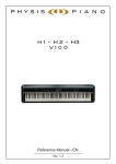
1
K4
K5
K4 EX
K5 EX
K4 GW
SOUND EXPANDABLE
MIDI/USB CONTROLLER
User Manual - EN
Ver. 1.3
User Manual – Table of contents
TABLE OF CONTENTS
1. Iimportant notes .................................................................................................................................................... 2
1.1 Looking after the product ............................................................................................................................................... 2
1.2 Notes about the manual.................................................................................................................................................. 2
2. Connections and controls ...................................................................................................................................... 3
2.1 Front panel ...................................................................................................................................................................... 3
2.2 Rear panel ...................................................................................................................................................................... 6
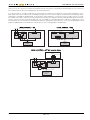
2.3 Connection examples ..................................................................................................................................................... 8
3. K4 / K5 structure ................................................................................................................................................... 9
3.1 Keyboard ........................................................................................................................................................................ 9
3.2 Controls .......................................................................................................................................................................... 9
3.3 Internal structure ............................................................................................................................................................. 9
4. Basic functions ................................................................................................................................................... 14
4.1 Switching on and main video page .............................................................................................................................. 14
4.2 Selecting Performance and Scene ............................................................................................................................... 14
4.3 Check Zone status ........................................................................................................................................................ 16
4.4 Selecting Control Banks ............................................................................................................................................... 16
4.5 Keyboard transposition................................................................................................................................................. 17
4.6 Screen visualisation modes .......................................................................................................................................... 17
4.7 Controls information ...................................................................................................................................................... 18
5. Checking and modifying a Performance (Info and Edit mode) ............................................................................ 19
5.1 Foreword on Info and Edit modes................................................................................................................................. 19
5.2 Modifying Scene and Performance name .................................................................................................................... 21
5.3 Saving a Performance .................................................................................................................................................. 21
5.4 Scenes .......................................................................................................................................................................... 22
5.5 Zones ............................................................................................................................................................................ 23
5.6 Control Banks ............................................................................................................................................................... 27
5.7 Wheels and pedals ....................................................................................................................................................... 30
5.8 Additional messages .................................................................................................................................................... 31
5.9 MIDI input maps ........................................................................................................................................................... 33
6. Sequence of Performances (Chain mode) ........................................................................................................... 35
6.1 Foreword on Chain mode ............................................................................................................................................. 35
6.2 Selecting a Chain.......................................................................................................................................................... 35
6.3 Programming a Chain ................................................................................................................................................... 36
7. General instrument settings (System mode) ........................................................................................................ 37
7.1 Foreword on System mode ........................................................................................................................................... 37
7.2 System MIDI and preferences ...................................................................................................................................... 37
7.3 Instrument preferences ................................................................................................................................................. 39
7.4 Programming Virtual Instruments.................................................................................................................................. 39
7.5 Configurating system controls ...................................................................................................................................... 42
7.6 System utilities, update and factory reset ..................................................................................................................... 46
8. Utility functions and data transfer ........................................................................................................................ 50
8.1 Initialising Scenes ......................................................................................................................................................... 50
8.2 Copying Scenes ........................................................................................................................................................... 51
8.3 Loading Performances or Virtual Instruments from internal memory or USB drive ....................................................... 52
8.4 Saving Performances or Virtual Instruments to the internal memory or USB drive ....................................................... 56
9. Troubleshooting .................................................................................................................................................. 58
9.1 Error messages............................................................................................................................................................. 58
9.2 Quick guide for frequent problems ............................................................................................................................... 59
10. MIDI .................................................................................................................................................................. 61
10.1 What is MIDI ............................................................................................................................................................... 61
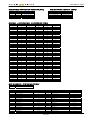
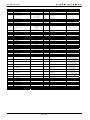
10.2 MIDI message tables .................................................................................................................................................. 63
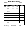
MIDI implementation chart ...................................................................................................................................................... 67
EN - 1
User Manual – Important notes
1. IMPORTANT NOTES
1.1 LOOKING AFTER THE PRODUCT
•
•
•
•
•
•
•
•
•
•
•
•
•
•
•
Do not apply excessive force to the instrument’s structures or the controls (buttons, connectors, etc.).
When possible, do not place the instrument close to units which generate strong interference, such as radios, TVs,
computer videos, etc.
Do not place the instrument close to heat sources, in damp or dusty places or in the vicinity of strong magnetic fields.
Do not expose the instrument to direct sunlight.
Never insert foreign bodies inside the instrument or pour liquids of any kind into it.
To clean the case, use only a soft brush or compressed air. To clean the tempered glass of the front panel, use
common glass detergents (for windows etc.).
Always use good quality screened cables for connection to amplification or diffusion systems. When disconnecting
cables from sockets, always take hold of the connector and not the cable itself; when winding cables, do not knot or
twist them.
Before making the connections ensure that the other units (especially amplification and diffusion systems) you are
about to connect are switched off. This will prevent noisy or even dangerous signal peaks.
If the instrument is to be out of use for lengthy periods, disconnect the plug from the power socket.
Connect the power cable to an earthed socket.
Check that the voltage corresponds to the voltage shown on the serial number plate of the device.
Clean periodically the power cable.
Only use the power cable provided with the instrument.
Do not place the power cable close to heat sources Do not damage the cable or bend it overmuch.
Do not place heavy objects on the cable. Do not place the cable where it could be trampled.
1.2 NOTES ABOUT THE MANUAL
•
•
•
•
•
•
•
•
•
Take good care of this manual.
This manual is an integral part of the instrument. The descriptions and illustrations in this publication are not binding.
While the instrument’s essential characteristics remain the same, the manufacturer reserves the right to make any
modifications to parts, details or accessories considered appropriate to improve the product or for requirements of a
constructional or commercial nature, at any time and without undertaking to update this publication immediately.
All rights reserved; the reproduction of any part of this manual, in any form, without the manufacturer’s specific written
permission is forbidden.
All the trademarks referred to in this manual are the property of the respective manufacturers.
Read all the information carefully in order to obtain the best performances from your product and waste no time.
The codes or numbers in square brackets ([ ]) indicate the names of the controls and connectors of the device. For
example, [ENTER] refers to the ENTER button.
The illustrations and display pages are purely guideline and may differ from those actually shown on the display.
The instructions provided in this manual only concern the instrument's operating system version that was up to date
when the document was released. Therefore, such instructions might not describe faithfully your current operating
system release. Please, visit the website http://www.viscountinstruments.com to check for the newest operating system
release and manual.
EN - 2 User Manual – Connections and controls
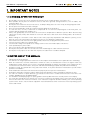
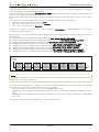
2. CONNECTIONS AND CONTROLS
2.1 FRONT PANEL
2
1
4
8
7
5
10
12 13
1
INIT
COPY
LOAD
< CHAIN
CHAIN >
SAVE
SCENE A
SCENE B
SCENE C
SCENE D
PANIC
HELP
SHIFT
3
6
9
11
14
15
1
Connectors' names: in order to ease the connections from and to K4 / K5, the names of the rear panel connectors
are written on the front panel.
2
Wheels: these three (in K4) or two (in K5) wheels can be pfreely programmed,
choosing the MIDI message that they will activate. The minimum and maxium value
can also be programmed. The left wheel always returns to the centre; although it can
be programmed, it is usually assigned to the Pitch Bend MIDI message, controlling
the pitch of connected instruments. For more information about wheel programming,
see chap. 5.7.
3
AUDIO Section: the [VOLUME] slider controls the volume of the internal sound board, Physis EX (for K4
EX / K5 EX models).
4
CONTROLLERS section: this section contains 9 knobs [KNOB 1] ... [KNOB 9], 9 sliders [SLIDER 1] ... [SLIDER 9]
and 9 buttons [BUTTON 1] ... [BUTTON 9] all of which can be programmed to control a MIDI message.
Knobs and sliders allow continuous control of a chosen parameter. Buttons only control on/off status or
increase/decrease by one unit at a time (1, 2, 3, 4, etc.). Buttons have bicolour Led lights. The Leds turn blue when
the button is pressed, or in "on" position. They turn red when the button is used to increase/decrease a value. There
are also four "bank" buttons [BANK 1] ... [BANK 4] to select control banks. K4 / K5 allows to create up to 4 controls
configurations, for each Scene. When a control bank is active, its Led light will be blue. Control banks with red lights
are inactive. Control banks with no light at all are currently disabled.
EN - 3
User Manual – Connections and controls
For more informations on Control Banks and control programming, see chap. 3.3 – Control Bank, and 5.6.
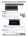
5
ZONES section: these buttons select Zones. The K4 / K5 Keyboard can be
divided into a maximum of 8 Zones, overlapping or not, sending out data to a
selcted output and MIDI channel.
Zones that are active in the currently selected Scene are indicated by blue Led
light. Inactive zones are indicated by a red Led light. Zones with no light are
disabled.
For more information on Zones, see chap. 3.3 - Zone.
6
[VIEW] button: this button is used to select the view mode of video pages on the
display. It affects the pages about Zones or other controls. When in SINGLE
mode (LED off), only one Zone and one control are shown. In ALL mode (LED on)
the page shows all Zones and controls, not just the one being currently adjusted.
This button has two functions. When pressed together with the [SHIFT] button
(press and hold) it recalls the Stand-by mode. The system will ask to confirm stand-by. Press [ENTER] to confirm.
STAND-BY MODE
When switching off the instrument through the [POWER] button, on the rear panel, all unsaved settings will be lost.
When switching it on again, the system will automatically select Performance P001. When switched off in this way,
the instrument is completely disconnected from any power source and will not consume electric energy.
Stand-By switches off the panel and the display reducing the current consumption. Pressing [VIEW] will reactivate
panel and display, and the instrument's settings will be as before.
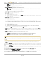
7
Display and buttons: this section of the front panel contains the high resolution
display (480 x 272 pixels, 4,7") and the "function" buttons [F1] ... [F4]. These
buttons are assigned different functions, depending on the video page. The
corresponding function is shown on the display, just above the relevant button.
These buttons also operate two functions. When pressed together with [SHIFT]
the secondary function is activated: they select a Scene in the current
performance. This works independently from the current video page. This is
their primary function while on the main video page of PERFORMANCE
MODE.
EN - 4 SCENE A
SCENE B
SCENE C
SCENE D
User Manual – Connections and controls
8
DATA ENTRY section: this section contains a rotating encoder to enter data. Turn the knob
clockwise to increase the currently selected value. Turn it counter-clockwise to decrease the
value. Below the encoder, there are two buttons that increase ([INC]) or decrease ([DEC]) the
value of a single unit/digit. They are used to "fine tune" parameters.
Press [SHIFT] in combination with these buttons to select the Performances contained in the
currently active Chain. (for further information, see chap. 6).
< CHAIN
9
CHAIN >
[SHIFT] button: many buttons on the front panel have also secondary functions, written close
to the button, inside a white field. To recall the secondary function, press [SHIFT], then hold it
while pressing the desired button. (e.g. [VIEW], to activate the stand-by mode).
SHIFT
10
CURSOR section: these buttons move the cursor.
[U]: move the cursor on the field above
[V]: move the cursor on the field below
[Y]: move the cursor to the left
[Z]:move the cursor to the right.
11
[TRANSPOSE] button: this button activates (Led on) or deactivates (Led off) transposition for
all Performances. When transposition is active, a "TRANSPOSE =" field will appear on the
PERFORMANCE MODE video page. This field show the transposition value in semitones. To
adjust transposition, press [TRANSPOSE], then hold it while rotating the encoder knob or
pressing the [DEC] and [INC] buttons to decrease/increase transposition by one semitone.
Pressing both at the same time nullifies transposition.
12
KEYPAD section: the buttons in this section can be used to enter text or digits,
depending on the selected field. Under the PERFORMANCE MODE screen, for
example, these buttons allow to select a Performance by entering its number; this field
only allows numbers. Other fields contain text, such as the rename Performance field. In
this case, letters can be entered by using these buttons. Numbers and letters related to
each button are written just below it.
These buttons have special functions:
[1 .,?!]: 1 and special characters.
[±]: symbol.
[0 SPACE]: 0 and space.
[CANC]: erase the character left from the cursor.
[EXIT]: quit the current page, cancel current data entry, or abort a procedure.
[ENTER]: access a video page to enter data, confirm entered data or confirm a
system request.
INIT
COPY
LOAD
SAVE
PANIC
HELP
Some of these buttons have a secondary function, recalled by pressing them together with [SHIFT]. These functions
depend on the context, that is, the current video page and the selected field.
[1 .,?!]: INIT function: initialize the selected item.
[4 GHI]: COPY function, copy and paste the selected item.
[7 PQRS]: LOAD function, load from internal memory or USB pen or Virtual Instrument.
[±]: SAVE function, save to the internal memory, or USB pen, or Virtual Instrument.
[EXIT]: PANIC function, mute all connected sound generation devices; also mutes the expansion board Physis
EX (in K4 EX / K5 EX models). Useful when, for unknown reasons, these are out of control and generate
unwanted sounds.
[ENTER]: HELP function, show the on-line guide. Press the button to read information on the
currently selected parameter (on the display).
For more information on these functions, see chap. 8.
13
MODE section: these buttons recall the 4 avialable operating modes for K4 / K5:
[INFO]: information mode; allows to check all configuration video pages of a Scene (and therefore
of a Performance). In this mode, data cannot be modified, so as to avoid unwanted changes to
parameters. For further information, see chap. 5.
[EDIT]: edit mode; allows full access to all Scene edit pages (and theferfore of the Performance),
and all parameters can be modified. For further information on this operating mode, see chap. 5.
[CHAIN]: Performance chain mode; allows creation and recalling of Performance chains, different
from the standard sequence (P001 - P128). For further information on this mode, see chap. 6.
EN - 5
User Manual – Connections and controls
14
[SYSTEM]: system mode; in this mode, the instrument's global parameters can be modified. System controls
(those that do not depend on the selected Scene) can be configured; Vistrual Instrument Tables can be
programmed, and all other additional functions can be accessed. For more infromation on this mode, see chap.
7.
[STORE] button: press this button to access the page where Performances are stored.
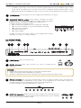
15
SEQUENCER REMOTE section: remote buttons controlling an external
sequencer or a computer DAW application (Digital Audio Workstation,
programs that play / record audio and MIDI) connected to K4 / K5.
The buttons perform the following functions:
[]: select previous song (press once) or rewind (press and hold)
[]: select next song (press once) or fast forward (press and hold).
[]: stop playing / recording.
[]: play selected song.
[ ]: starts recording.
The MIDI message sent out by these buttons can be programmed. For further
information, see chap. 7.5 – Sequencer Remote.
2.2 REAR PANEL
1
2
3
4
5
6
1
[POWER] button: switch on and off K4 / K5.
2
[AC-IN] connector: power cable connector. The cable is included with the
instrument.
7
8
WARNING!
• Always make sure that the power supply is connected to an earthed socket.
• Always use the power cable included with the instrument.
• Should the instrument be out of use for a long time, disconnect the cable from the power socket.
3
PEDALS connectors: jack connectors for pedals. Up to 8 switch or expression pedals can be connected at the
same time. As with the CONTROLLERS section, pedals can be programmed to activate MIDI messages; the
messages and their minimum and maximum values can be fully programmed.
For further information on pedal programming, see chapter 5.7.
4
AUDIO OUT connectors: balanced jack connectors sending out the audio signal from the
internal sound board Physis EX (for models K4 EX and K5 EX). Use only the [L/MONO]
connector if you need a monophonic output.
EN - 6 User Manual – Connections and controls
5
[PHONES] connector: stereo jack connector, sending out the signal from the internal sound board Physis EX (for
models K4 EX and K5 EX). Use with Headphones.
NB
•
The AUDIO OUT outputs have balanced connections and can be used with either mono or stereo jacks/cables. If
using mono jacks/cables, or devices with unbalanced inputs, the signal level is 6dB lower than when using stereo
jacks/cables. Furthermore, connections made using balanced cables (stereo jacks and cables) are much more
immune to interferences.
Cold
Cold
Ground - Cold
Ground - Cold
Hot
Hot
Ground
Ground
Hot
STEREO JACK (BALANCED)
•
6
Hot
MONO JACK (UNBALANCED)
Keep in mind that using headphones at high volume might cause hearing loss.
USB
connectors: this section contains all the available USB connections, that can be
used as follows:
[HOST 1-2] and [HOST 3-4]: insert here the USB cable from sound generation devices,
or a USB pen to which you can save/load your configurations and settings. Can also be
used with USB control lights
[DEVICE]: connect here the USB from a computer, in order to use MIDI applications.
NB
•
•
•
•
•
•
Use an A/B type USB cable.
Always connect the cable while the instrument is switched off.
Before connecting the cable to a computer, exit the power saving mode on the computer.
After connecting the computer through the [DEVICE] connector for the first time, wait while the Physis Piano
driver is installed on the computer (a message will inform you that new hardware has been installed and is ready
for use).
When connecting a USB cable or switching on K4 / K5 while it is connected to a computer, always wait
approximately 5 seconds before starting MIDI applications.
Once a devide is connected to the [HOST 1-2] and [HOST 3-4] connectors, wait for the pop-up message “USB
PLUGIN HOST NOTIFICATION” before operating on the device. In case the message does not appear, make
sure that the USB cable is properly working and the connected device is switched on.
7
MIDI OUT connectors: 5 pin MIDI DIN connectors for sending out MIDI data. Can used to connect K4 / K5 with a
maximum of 128 devices (16 MIDI channels for 8 ports) at the same time.
For further information on MIDI protocol, see chap. 10.
8
MIDI IN connectors: 5 pins MIDI DIN connectors, receiving MIDI data. Can be used to play the
internal sound board Physis EX (in models K4 EX and K5 EX) through an external device. The
incoming data from the MIDI IN port can be sent out to the MIDI OUT connectors; redirecting can be
set individually for each Scene.
EN - 7
User Manual – Connections and controls
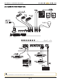
2.3 CONNECTION EXAMPLES
MIC 1
MIC 2
MIC 3
TAPE
MIC 4
L
Mono
EFF.
AUX 1
R
LINE 2
- 40 dB
+ 4 dB
TRIM 1
- 15
LINE 3
- 40 dB
+ 4 dB
TRIM 2
+ 15
- 15
L
+ 15
- 15
+ 15
- 15
HI
- 15
+ 15
- 15
+ 15
- 15
HI
- 15
MID
LOW
+ 15
+ 15
- 15
+ 15
- 15
+ 15
- 15
+ 15
L
R
R
LINE 5-6
LINE 7-8
+ 15
- 15
+ 15
- 15
+ 15
- 15
HI
+ 15
- 15
+ 15
- 15
+ 15
- 15
R
MAIN OUTS
L
Mono
L
Mono
+ 15
- 15
+ 15
- 15
+ 15
- 15
- 15
+ 15
- 15
+ 15
- 15
HI
+ 20
RET. to MAIN
+ 20
+ 15
RET. to AUX
+ 20
+ 15
TAPE IN
LOW
+ 15
AUX 1/EFF.
+ 15
HI
MID
LOW
+ 15
AUX 1/EFF.
PHONES
LINE 11-12
+ 15
MID
LOW
+ 15
AUX 1/EFF.
+ 15
MID
LOW
R
R
LINE 9-10
HI
MID
LOW
AUX 1/EFF.
+ 15
HI
MID
LOW
AUX 1/EFF.
- 40 dB
TRIM 4
MID
LOW
AUX 1/EFF.
+ 4 dB
HI
MID
- 15
L
R
OUT
IN
AUX OUT
Mono
LINE 4
- 40 dB
TRIM 3
+ 15
L
AUX 2
AUX RETURN
Mono
LINE 1
+ 4 dB
+ 15
AUX 1/EFF.
+22
AUX 1/EFF.
+10
+7
+4
+2
+ 15
+ 15
AUX 2
+ 15
AUX 2
+ 15
AUX 2
+ 15
AUX 2
+ 15
AUX 2
+ 15
AUX 2
+ 15
AUX 2
AUX 2
0
-2
-4
-7
L
R
L
PAN
R
L
PAN
R
L
PAN
R
L
PAN
R
L
PAN
R
L
PAN
R
L
PAN
-10
R
PAN
-20
-30
MUTE
MUTE
SOLO
10
MUTE
MUTE
10
5
U
SOLO
SOLO
10
5
U
MUTE
SOLO
10
5
U
MUTE
SOLO
10
5
U
SOLO
10
5
U
10
5
U
5
U
U
5
5
5
5
5
5
5
5
5
10
10
10
10
10
10
10
10
20
20
20
20
20
20
20
20
20
30
30
30
30
30
30
30
30
30
40
40
40
40
40
40
40
40
40
50
50
GAIN 1
EN - 8 MUTE
SOLO
10
5
U
NB
Always remember to connect the devices before switching them on.
MUTE
SOLO
10
5
10
50
GAIN 2
50
GAIN 3
50
GAIN 4
50
GAIN 5-6
50
GAIN 7-8
50
GAIN 9-10
50
GAIN 11-12
MASTER
User Manual –K4 / K5 structure
3. K4 / K5 STRUCTURE
3.1 KEYBOARD
The instrument can be equipped with three different kinds of keyboard:
K4 GW: Hammer Action keyboard, 88 graded-hammer wooden keys, Ivory Feel, PGK Physis Grand Keyboard;
K4 / K4 EX: lightweight keyboard, 88 graded keys;
K5 / K5 EX: lightweight keyboard, 76 graded keys.
All keyboards are dynamic sentitive to aftertouch; sensitivity varies according to the selected curve for each Zone. Users
can create their own dynamic response curve, point by point, through a simple, intuitive procedure.
3.2 CONTROLS
K4 / K5 has five different kinds of controls:
3 (K4) or 2 (K5) wheels (WHEEL on panel and display)
9 knobs (KNOB on panel and display)
9 cursors (SLIDER on panel and display)
9 buttons (BUTTON on panel and display)
8 pedals (PEDAL on panel and display)
All these controls can be programmed, setting the MIDI message that they activate, its minimum and maximum value, and
the standard value when a Scene is selected. Buttons also allow “momentary” control (status changes while the button is
pressed), “toggle” (status changes each time the button is pressed), or “step” (value is increased or decrease of one unit
each time the button is pressed).
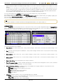
3.3 INTERNAL STRUCTURE
The internal memory of a K4 / K5 is organized in a 128-Performance bank. Performances allow to save different
configurations that can be quickly recalled without programming the instrument every time. The main sections of the
internal structure are displayed in the picture below:
Here is a detailed descritpion of each section.
EN - 9
User Manual – K4 / K5 structure
PERFORMANCE
A Performance contains 4 Scenes, and is a practical way to group and recall Scenes quickly. Thanks to perfofrmances, the
musician can switch quickly between scenes. Only one Scene can be active for each Performance. Two Scenes cannot be
active at the same time.
Scenes (SCENE A-B-C-D) can be selected by pressing the function buttons [F1], [F2], [F3] and [F4] from the main video
page.
A Performance affects the instrument by determining:
the scenes that can be selected, and which of these scene is active (only one at a time).
As already stated, a maximum of 128 Performance can be created. Performance can be saved to the internal memory or to
a USB pen, and reloaded when needed. The user can thus create an unlimited library of Performances.
SCENE
A Scene is a program containing all information needed to configure an instrument. more precisely a Scene contains
information about:
8 Zones,
4 Control Banks, each with 9 Knobs, 9 Sliders and 9 Buttons,
8 pedali Pedals,
3 or 2 Wheels,
8 Input Maps,
8 initializing messages (Messages).
Scenes determine the functioning of all the components of the instrument, such as keyboard, knobs, and all controls.
A Scene can be active, inactive o disabled. The status of a Scene is indicated on the lower part of the PERFORMANCE
MODE video page (see chap. 5.4), according to this rule:
• Scene name in white, and indicated by the cursor (light blue rectangle): this Scene is active, Zones and Controls work
as set by the current Scene.
• Scene name in white, without cursor: this Scene is inactive, Zones and Controsl work as determined by the active
Scene. The inactive Scene is however available.
• Scene name in gray: this Scene is disabled, Zones and Controls work as set by the active Scene. The disabled Scene
cannot be activated.
ZONE
A Zone is a portion of the keyboard. It can have any range from one key to the whole keyboard, A Zone allows to
reproduce the sound of a MIDI instrument connected to a K4 / K5 output. For each Zone, the following parameters can be
set:
output port (Output) and MIDI channel (Channel),
program (Program Change) and program bank (Bank Select),
volume (Volume), stereophonic panoramic (Pan), reverb send (Reverb) and effect send (Chorus),
transposition (Note Shift),
Enable and assign a MIDI message to aftertouch,
velocity curve (Velocity Curve) and velocity range (Velocity Range),
aftertouch curve (Aftertouch).
Keyboard range
The instrument can manage a maximum og 8 Zones at the same time. These Zones can control external MIDI devices
through the MIDI and USB ports, or the internal sound board Physis EX (in models K4 EX / K5 EX). Therefore, a maximumof
8 different sounds can be played at the same time, and distributed along the keyboard at the user's needs.
Each Zone can be active, inactive, control or disabled. The status of the Zone is indicated by the LED on the button
[ZONE 1] ... [ZONE 8] and on the main screen PERFORMANCE MODE (see par. 4.3):
• The button led and the display rectangle are both blue: the area is active. The notes of the keyboard, the messages
assigned to the controls, the messages of sound selection and auxiliary, and those received by the MIDI inputs are
transmitted in accordance with what is set for that Zone.
• The button led and the rectangle on the display are both red: the area is inactive. Are only transmitted messages
assigned to controls, those of sound selection, auxiliary messages, and those received by the MIDI input ports, but the
notes of the keyboard are not transmitted. The area is still activatable.
• The button led is turned off, the display rectangle is light gray: the Zone is a control one. Are only transmitted
messages assigned to controls, those of sound selection and auxiliary, and those received by the MIDI input ports,
while the notes of the keyboard are not transmitted. The Zone is not activatable.
• The button led is turned off, the display rectangle is dark gray: the area is disabled. The notes of the keyboard, the
messages assigned to controls, initialization messages and those received by the MIDI input are not transmitted. The
Zone is not activatable.
EN - 10 User Manual –K4 / K5 structure
Having a Zone in inactive mode (red Led) is useful when the notes of a certain Zone are needed only at a certain stage of
the performance, and not before. Instead, a disabled Zone is completely unavailable in the current Scene. This helps avoid
undesired or accidental activation of that Zone during the performance. If you want a Zone send MIDI messages assigned
to the controls but it is never activated from the panel in order to avoid this Zone sounds on the keyboard (used, for
example, to configure an external device), the Zone must be set as a control zone. The disabled state (LED off) determines
the absolute absence of that part within the current Scene. and prevents it from accidentally turning on and the
transmission of MIDI messages which may be allocated to the controls.
To activate a disabled Zone, access the edit mode (EDIT MODE menu), described at chap. 6.
VIRTUAL INSTRUMENTS
As mentioned before, each Zone can be assigned an output MIDI port, through which MIDI data is sent to external
devices. In K4 / K5 these ports are MIDI OUT, USB [DEVICE], [HOST 1-2] and [HOST 3-4] connectors.
When programming a Zone, when selecting a MIDI output, the display shows the name of the connector, though not that of
the instrument, since it cannot be known.
To overcome this problem, K4 / K5 has a set of tables, called Virtual Instruments, that associate each MIDI connector to an
external device. Thanks to these tables, when programming a Zone it is not necessary to remember the MIDI connector,
but only the device. Furthermore, the names of available sounds, programs and controls for a certain device can be
defined by the user. This means that the user does not need to use the code of a Program Change, or the type and code of
MIDI message assigned to a control or parameter.
When selecting a Virtual Instrument, K4 / K5 activates the connector assigned to that instrument, and the sound selection
screen shows the names of the available sounds for that external instrument; in the same way, when setting the controls,
the name of the external controls and/or parameters for that external device will be shown. Therefore, when using K4 / K5
with other MIDI devices, it is important to program the Virtual Instrument tables as soon as possible. Thanks to the tables,
programming Performances is much easier and faster, since the names of the devices and their sounds and parameters
are shown on display. A maximum of 10 Virtual Instrument tables are available and can be programmed. Each table has 8
sound banks, a Control Change table and an NRPN table. Virtual Instruments can be saved to the internal memory, or to a
USB pen, allowing an unlimited library.
CONTROL BANK
The control bank contains settings for knobs, sliders and buttons on the left side of the front panel, called CONTROLLERS
section.
Knobs can be rotated up to 360° degrees, without end, so as to allow continuous control of the assigned parameter. The
function mode of each knob can be selected: the value controlo can be relative or absolute. In relative mode, the value
increases/decreases starting from the value saved to the Control Bank. In absolute mode, the value set by the knob
remains even when changing Scene or Performance.
Slider cursors also allow continuous control of a parameter. Having a fixed extention, they are precise and quick. They
have an inverse mode, simulating, for example, electromagentic organ drawbars. Control parameters can be set to imitate
such effect.
Buttons are equipped with Leds and have three different function modes:
Normal: by standard, the value is at minimum and the Led light is off. While pressed, the value is at its maximum and
the Led light is blue;
• Toggle: each time the button is pressed, the value is toggled between maximum (blue Led) and minimum (Led light
off);
• Step: each time the button is pressed, the value is increased or decreased by one unit (Led light red).
•
Each of these control can send a maximum of 8 different messages at the same time, one for each Zone. Therefore, it is not
necessary to define the output and MIDI channel for the control: the message acquires the channel and output from each
Zone.
Each of these 8 messages can also be assigned a minimum and maximum value. This way, each message can have its
own value range, while keeping the same proportion. This is why the control value is expressed by percentage.
It is also possible to use the controls in inverted mode, by setting the minimum value higher than the maximum.
NB
The value of K4 / K5 controls is always shown on the display as a percentage, from 0% to 100%. This is to ensure that
the value transmitted by different MIDI messages (one for each Zone, for a maximum of 8 values) assigned to a
control. This means that parameters for different Zones can be managed together through the same controller; values
will be calculated and sent out to different Zones in a balanced way, that is, keeping the same percentage for each
Zone although the actual value might vary. For example, let us assume that a controller is assigned the MIDI message
"volume" (Control Change 7), but that the range for the first Zone is 0-127 and the range for the second zone is 50100. When the controller is positioned at half range (50%), the value is 63 for one Zone and 75 for the other. The
volume variation by percent, however, is the same for both Zones.
EN - 11
User Manual – K4 / K5 structure
Each Scene has a maximum of 4 available banks, so that there are 108 programmable controls in total. To select the
Control Bank, use the [BANK 1], [BANK 2], [BANK 3] and [BANK 4] controls, from the CONTROLLERS section on the front
panel.
Each Control Bank can be active, inactive or disabled. The status of Control Banks is indicated by the button Led. Each
bank has its own Led button: [BANK 1], [BANK 2], [BANK 3] and [BANK 4]. The rule is:
• Blue Led light: the Control Bank is active, Bank settings affect the controls,
• Red Led light: the Control Bank is inactive, controls follow the settings of the active bank. However, this bank can be
activated.
• Led light off: the Control Bank is disabled, controls follow the settings of the active bank and this bank cannot be
activated.
There can be only one active Control Bank at a time. Disabled control banks cannot be activated, unless they are modified
under the EDIT MODE menu, described at chap. 6.
If use of knobs, sliders or buttons are not necessary, you can also disable all Banks Controls, with the additional advantage
of avoiding unwanted transmissions inadvertently touching one of these controls.
PEDALS
This section contains settings for the 8 pedals that can be connected to the [PEDAL 1] ... [PEDAL 8] connectors on the rear
panel. Pedals can be configured from the SETUP / PEDALS video page under the SYSTEM menu. Available settings are
pedal type (switch or expression), polarity and calibration.
Once the pedal has been configured, it can be programmed as all the other controls. Pedal (as controls) can tramsit a
maximum of 8 different MIDI messages (one for each Zone). Each message has its own minimum and maximum value.
Just like buttons, the operating mode of switch pedals can be manually set for each Scene. Three modes are available:
• Normal: by standard, the value is at minimum. While the pedal is pressed, the parameter reaches the maximum value;
• Toggle: each time the pedal is pressed, the value is toggled between maximum and minimum;
• Step: when the pedal is pressed, the value is increased or decreased by one unit.
Differently from Control Banks, pedals can be assigned a system function under the SETUP / PEDALS page, from the
SYSTEM menu. These system function override Scene settings. A pedal to which a system function has been assigned,
sends out the same MIDI message to all Zones, in spite of the currently selected Performance and Scene. Such function
can be used, for example, to make a Sustain pedal (Control Change 64), always available without programming it for each
Scene. However, a pedal with a system function can be programmed so as not to affect one or more Zones.
WHEELS
This section contains the Wheels on the front panel. The leftmost wheel, ([WHEEL 1]) always returns to central position. This
wheel can be programmed like the others, although it is usually associated with Pitch Bend MIDI messages.
Just like any other control, wheels can be programmed, so as to transmit a maximum of 8 different MIDI messages, one for
each zone. Each message has its own minimum and maximum value.
Like pedals, each wheel can be assigned a system function, from the SETUP / WHEELS page, under the SYSTEM menu.
System functions override Scene settings. This means that a wheels with system functions sends out the same MIDI
message to all Zones, in spite of the currently selected Scene Performance and Scene. For example, [WHEEL 1] can be
assigned the Pitch Bend function, which works for all Scenes, without setting it every time.
MESSAGES
In this section, MIDI messages can be programmed, up to 8 auxiliary messages for each Scene. These messages are
transmitted as soon as a Scene is selected. These messages initialize external devices or program them. This is why these
are called Initializing Messages.
The Messages section is the only section that can set System Exclusive messages. These are MIDI messages that each
manufacturer can freely set for an instrument, and set internal parameters of the connected instrument that cannot be
modified otherwise.
INPUT MAP
Input maps can be created in this section, up to 8 maps for each Scene. These maps connect a MIDI channel and input to
an ouptut port and channel; filters can be added, such as a Program Change filter, or Control Change filter etc.
Input maps allow to expand even further the K4 / K5 controls, thanks to external devices or keyboards, connected to the K4
/ K5 inputs.
MIDI COMMON
In addition to the MIDI ports and transmission channels used by the Zones of the selected Performance, you can activate
an additional port and channel for the transmission and reception of System MIDI messages. System messages are those
MIDI data transmitted as a result of the operation performed on the keyboard, panel and pedals, and which are
independent from the configurations that are set by Performance. Therefore, even selecting other Performance or Scenes,
or disabling Zones, are always transmitted the same MIDI messages playing on the keyboard (Note) and acting on the
panel and pedals (Control Change), always on the same Midi port and MIDI channel. When received at the port and
EN - 12 User Manual –K4 / K5 structure
channel set on the system, the instrument interprets them as if they were real operations performed by the user, which are
then redirected to the Zones according to the selected Performance.
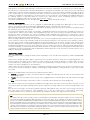
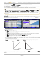
It is also possible to exclude completely the functionality of Performance, through the Local Control parameter. This is
particularly useful if you want K4 / K5 send MIDI messages only of the actions that are performed on the keyboard, panel,
and pedals, excluding the programming set for the Zone and Performance. In this way, these messages can be received,
for example, by a device which in turn re-transmits them, possibly also together with other data generated by itself or other
devices, which must then be performed by K4 / K5 according to selected Performance and Zones. Without the Local
Control parameter, the performance would perform both the operations performed by the user on the keyboard panel and
pedals, and MIDI data received from the external device, thus creating problems of MIDI loops.
LOCAL CONTROL = ON
LOCAL CONTROL = OFF
Performance
Out1 Out2
Physis EX
Performance
In1
Out3
Out1 Out2
Physis EX
MIDI Common
Out3
MIDI Common
Z1 Z2 Z3
Z1 Z2 Z3
Local Control = On
Local Control = Off
Keyboard
Panel controls
Pedals
Keyboard
Panel controls
Pedals
LOCAL CONTROL = OFF with external device
External
device
MIDI Thru = On
Out
In
In1
Out3
Performance
Out1 Out2
In1
Physis EX
MIDI Common
Z1 Z2 Z3
Local Control = Off
Keyboard
Panel controls
Pedals
EN - 13
User Manual – Basic functions
4. BASIC FUNCTIONS
4.1 SWITCHING ON AND MAIN VIDEO PAGE
After connecting the cables, press the [POWER] button on the rear panel to switch on K4 / K5.
NB
The instrument needs time to load all of its settings, and therefore, it is not immediately ready after switching on.
During the process, introductory images appear on screen. When the main video page appears, the instrument is
ready. When the instrument is ready, switch-on images disappear and the main video page appears on the display. Now the
instrument is ready.
If the internal sound board Physis EX has been installed, (only for K4 EX and K5 EX), the [AUDIO] slider controls the
general volume.
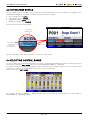
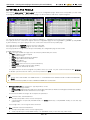
The standard mode is PERFORMANCE MODE. It is the most common mode and shows general data on the selected
Performance.
Current function
mode
Performance Location – Performance Name / Scene Name > current page name
Performance
name
Performance
Location
Performance subheading
or comment
Currently selected
(active) Scene
Current Scene Name
Zones status
Active Scenes
Enabled Scenes,
can be selected
through function buttons
Disabled Scenes
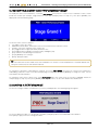
4.2 SELECTING PERFORMANCE AND SCENE
There are three ways to select a performance while in PERFORMANCE MODE:
• rotate the encoder,
• press the [DEC] and/or [INC] buttons,
• enter the code of a Performance location, by using the KEYPAD section buttons.
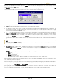
• Press [ENTER] to display the list of all the available Performance:
EN - 14 User Manual – Basic functions
selecting and moving the cursor with the encoder or the buttons [U], [V], [Y] or [Z] and press [ENTER]. Press [EXIT] to
return to the display screen PERFORMANCE MODE.
To select a different Scene from the PERFORMANCE MODE page, just press the function buttons: [F1], [F2], [F3] and
[F4]: a new Scene will be immediately activated.
While on other video pages, press [SHIFT] and a function button ([F1], [F2], [F3] and [F4]) at the same time to select a
Scene.
Only active Scenes, shown in white, can be selected. Scene mode is displayed in the following way:
• White Scene name, with cursor: the Scene is active.
• White Scene name, without cursor: the Scene is inactive.
• Scene name in grey: the Scene is disabled.
Disabled Scene cannot be activated, unless they are enabled in EDIT MODE. To enable/disable a Scene, follow the
procedure described in chap. 5.4.
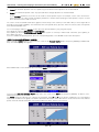
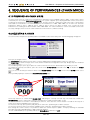
When selecting a Scene, the instrument sends out MIDI message in this order (whatever output or Virtual Instrument has
been selected):
1. Initializing Messages (settings can be found on the page EDIT MODE \ MORE \ MESSAGES)
2. Sound selection messages in Zones (settings can be found on the page EDIT MODE \ ZONES \ CONFIG)
3. Sound parameters (settings can be found on the page EDIT MODE \ ZONES \ PARAMETERS)
4. Starting value for buttons (settings can be found on the page EDIT MODE \ CLTR BANKS \ BUTTONS)
5. Starting value for sliders (settings can be found on the page EDIT MODE \ CLTR BANKS \ SLIDERS)
6. Starting value for knobs (settings can be found on the page EDIT MODE \ CLTR BANKS \ KNOBS)
7. Starting value for pedals (settings can be found on the page EDIT MODE \ PEDALS+WHEELS \ PEDALS)
8. Starting value for wheels (settings can be found on the page EDIT MODE \ PEDALS+WHEELS \ WHEELS)
SCENE SELECTION
Loading of
Scene data
8
WHEELS
messagges
7
PEDALS
messagges
6
KNOBS
messagges
5
SLIDERS
messagges
4
3
2
1
BUTTONS
messagges
ZONE
PARAMET.
messagges
ZONE
CONFIG
messagges
MESSAGES
messagges
Output
NOTE
Initialization messages can also be transmitted at the end of the sequence described above, rather than the
beginning. To this end, see chap. 5.8. That said, always program Zones carefully, so as to avoid multiple repetitions of the same Message. The last MIDI
message sent is the one that eventually define the value. If, for example:
− the volume for Zone one has been set as 127 (in the PARAMETERS section),
− [SLIDER 1] has been assigned Control Change n.7 (Volume) for Zone 1, with 90% as starting value (MIDI value is then
100),
−
[KNOB 4] has been assigned the same Control Change to the same Zone, but with a starting value of 50% (MIDI
value = 64),
eventually the sound volume will have MIDI value = 64, as set by the knob.
EN - 15
User Manual – Basic functions
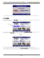
4.3 CHECK ZONE STATUS
Use the buttons from the ZONES section to activate and deactivate Zones. As for the LEDs of the [ZONES], also
PERFOMANCE MODE screen informs you about the status of the Zone, therefore:
• blue rectangle: Zone is active.
• red rectangle: Zone is inactive.
• light gray rectangle: control Zone.
• dark gray rectangle: Zone disabled.
These fields also show further information:
Transmitting
MIDI port name
Zone number
Transmitted
Program Change
or selected Sound
MIDI channel
For more information on the status of the Zones, see par. 3.3 - Zone section.
4.4 SELECTING CONTROL BANKS
To select a different Control Bank among inactive ones (keep in mind that disabled banks cannot be activated, unless they
are previously enabled in EDIT MODE), press the corresponding button [BANK 1] ... [BANK 4].
The button Led turns blue, while the Led light of inactive banks turns red. The display shows for a few seconds the initial
settings of the controllers (CONTROLLERS section) for the current Control Bank.
These can be set in in EDIT MODE:
Pressing twice quickly, the [BANK 1] ... [BANK 4] button, the screen remains until the pressure of the same button or
another [BANK 1] ... [BANK 4], or [EXIT] .
EN - 16 User Manual – Basic functions
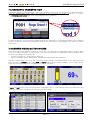
4.5 KEYBOARD TRANSPOSITION
Transposition affects the whole keyboard, in spite of the currently selected Scene or Performance. To apply transposition,
press the [TRANSPOSE] button. When the Led light is on, the function is active, otherwise it is inactive.
The PERFORMANCE MODE page shows the transposition value in semitones:
To adjust transposition, press and hold the [TRANSPOSE] button and rotate the encoder [DATA ENTRY] or press [DEC] to
decrease, or [INC] to increase. the transposition range is of ± 24 semitones. Pressing both at the same time nullifies
transposition.
4.6 SCREEN VISUALISATION MODES
Some video pages have different visualisation modes: they can either show all information together, giving a global
overview, or only the information relevant to what is currently being modified. The [VIEW] button switches between these
two modes, according to the following rule:
− when the Led light is on, all information is displayed
− when the Led light is off, the display shows only information about what is being modified
Two types of video pages have these two view modes: pages related to the CONTROLLERS section (front panel) and
pages about Zones (ZONES section under INFO and EDIT modes). Using a control ([SLIDER 1] in the example below),
one of these two pages will appear, according to the selected view mode.
VIEW=ALL
VIEW=SINGLE
In INFO and EDIT modes, when visualizing a Zone configuration (Zone 1 in the following example) the display will show
one of these two pages, according to the currently selected view mode:
VIEW=ALL
VIEW=SINGLE
EN - 17
User Manual – Basic functions
4.7 CONTROLS INFORMATION
When using a control from the CONTROLLERS section, an information page appears, showing either a general overview on
the whole section or specific information for the current control.
Control Bank
status
Control Bank name
Control Bank number
Knobs names and values
Sliders names and values
Buttons names and values
VIEW=ALL
Current control value
Percent control value
Control name
VIEW=SINGLE
EN - 18 User Manual – Checking and modifying a Performance (Info and Edit Mode)
5. CHECKING AND MODIFYING A PERFORMANCE
(INFO and EDIT MODE)
5.1 FOREWORD ON INFO AND EDIT MODES
INFO mode allows the user to see all parameters of a Scene, while in EDIT mode they can also be modified. INFO and
EDIT mode can be accessed through the related buttons in the MODE section. So, the only difference between the two
modes is that INFO MODE is in read-only mode. It allows to see all information on the selected Scene, but no changes can
be made while in this mode. This chapter deals with both modes at the same time.
The currently selected mode is shown by the button Led lights, and also on the top right of the display; furthermore, while
in EDIT mode, a cursor appears on the display.
Current oparating
mode
Cursor
Current operating
mode
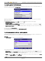
The video above is the main menu for both operating modes. From here, all configuration pages can be accessed. They
are grouped into four section, that can be accessed by pressing the function buttons:
[F1]: ZONES section, containing Zones settings.
[F2]: CTRL BANKS section, containing Control Banks settings.
[F3]: PEDALS+WHEELS section, containing Pedals and Wheels settings.
[F4]: MORE section, containing Initialization Messages and Input Maps settings.
All pages in these four sections are segmented in rows and columns. The 8 rows correspond to the 8 Zones, indicated on
the leftmost column as Z1, Z2, Z3 etc. Columns show the configuration parameters.
The ZONES section also has two view modes, that can be switched by pressing the VIEW button on the front panel.
When the view mode is set as ALL, the page is divided into rows and columns as explained before. When the view mode is
set as SINGLE, the display shows one single Zone at a time. The Zone number can be found on the top left.
Parameters are in the centre of the display. To change Zone, place the cursor on the ZONE field and enter a different
number by following the procedure described below.
EN - 19
User Manual – Checking and modifying a Performance (Info and Edit Mode)
Here is an example of the display in both view modes:
VIEW=ALL
VIEW=SINGLE
To move the cursor, use the arrow buttons: [U], [V], [Y] and [Z].
Press [EXIT] to leave the page and go back to the INFO MODE or EDIT MODE menu (depending on the current operating
mode), or press [INFO] or [EDIT] (as before) to go back to PERFORMANCE MODE.
To toggle between these modes, use the related buttons in the MODE section of the front panel.
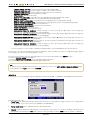
To enter data in the system, use the the encoder, the [DEC] and [INC] buttons, the KEYPAD section buttons, or press
[ENTER].
When pressing KEYPAD buttons or [ENTER], the following pages appear:
pressing KEYPAD buttons
pressing [ENTER]
These example pages appear when trying to enter data in the Program Change column:
On the first example page, to move the cursor (the white bar) press the arrow buttons [Y] and [Z].
Function buttons [F1], [F2], [F3] and [F4] perform the functions shown on the display, just above each button. Press [F1] to
select the minimum available value for each parameter; press [F2] to select the maximum value. Press [F3] to erase all
data; press [F4] (or [ENTER]) to confirm and return to the previous page. To cancel the procedure, press [EXIT].
On the second example page, use the arrow buttons [U], [V], [Y] and [Z] to move the cursor (the white rectangle).
Press [F4] (or [ENTER]) to select the value indicated by the cursor; press [F3] (or [EXIT]) to cancel selection. In both cases,
the display will return to the previous page.
Other functions may be available. In this example, [F2] enters the “OFF” value.
NB
Changes made to a Scene parameters by following the procedure explained in this chapter will be retained when
selected a different Scene but are lost when selecting a different Performance (unless they have been saved). EN - 20 User Manual – Checking and modifying a Performance (Info and Edit Mode)
5.2 MODIFYING SCENE AND PERFORMANCE NAME
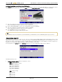
To modify the name of a Performance, recall the EDIT MODE, then place the cursor on the Performance name, shown
beside the location (for example “Stage Grand 1” in the first example picture of chap. 5.1), then press [ENTER]. The
display will show the following page:
To enter the name use these buttons:
[Y] and [Z]: move the cursor.
KEYPAD section buttons, or Encoder: insert a new character to the left of the cursor.
[CANC]: cancel the character to the cursor's left.
[F1]: toggle between upper (full arrow) and lower case.
[F2]: toggle between alphabet characters (abc) and digits (123).
[F3]: clears the field, deleting all characters.
[F4] or [ENTER]: save changes.
[EXIT]: abort procedure.
NB
The new name will not be saved unless the Performance is saved. If a new Performance is recalled without first
saving the current one, the new name will be lost. To change the Performance subheading or comment, access the EDIT MODE, then place the cursor on the Performance
subheading (called “Ac. Piano” in the first example page of chap. 5.1) then press [ENTER]; to change the name, use the
same buttons described before.
To change the name of the current Scene, enter EDIT MODE, place the cursor on the Scene name (“GRAND” field in the
example page at chap. 5.1) then press [ENTER]; to change the name, use the same buttons described before.
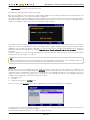
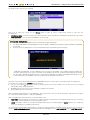
5.3 SAVING A PERFORMANCE
To save the changes made to a Performance, press the [STORE] button. The following page will appear:
To select a different location, use the Encoder, the [DEC] and [INC] buttons or the KEYPAD section buttons.
Press [EXIT] or [F3] to leave the saving procedure.
EN - 21
User Manual – Checking and modifying a Performance (Info and Edit Mode)
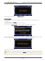
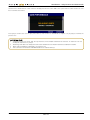
Press [ENTER] or [F4] to save the Performance. A system message appears:
Now press [ENTER] or [F4] to confirm and save; otherwise, press [EXIT] or [F3] to abort and return to the previous page.
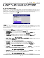
5.4 SCENES
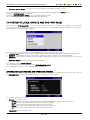
To enable or disable a Scene enter EDIT MODE, then select the Scene from the left field (see picture) suing the [DEC] and
[INC] buttons or the encoder:
Scene selection
field
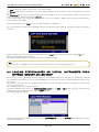
An alternative procedure to disable a Scene is to select it from the PERFORMANCE MODE by pressing the function
buttons and then recall EDIT MODE; then place the cursor on the square beside the Scene name:
Enable/disable
Scene field
then press the [DEC] and [INC] buttons or use the encoder to enable ( ) or disable (empty field) the Scene.
9
Keep in mind that a disabled Scene cannot be selected in PERFORMANCE MODE, mainly to avoid selecting the Scene by
mistake. A disabled Scene is shown in grey on the display, above the function buttons (see example page at chap. 4.1).
EN - 22 User Manual – Checking and modifying a Performance (Info and Edit Mode)
5.5 ZONES
From the INFO MODE and EDIT MODE menus, press [F1] to access the setting pages, containing the parameters for the
8 Zones of each Scene. These parameters have been described in chap. 3.3 under the “Zone” paragraph.
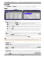
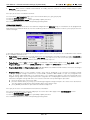
CONFIG
The first page of the menu, called CONFIG, and contains settings about MIDI channels and sound selection messages:
VIEW=ALL
VIEW=SINGLE
The following parameters can be modified:
Status: Zone status, can take the following values:
- DIS (Disabled): the Zone is disabled. The notes of the keyboard, the messages assigned to controls, initialization
messages and those received by the MIDI input are not transmitted. The Zone is not activatable.
- CTRL (Control): the Zone is a control one. Are only transmitted messages assigned to controls, those of sound
selection and auxiliary, and those received by the MIDI input ports, while the notes of the keyboard are not
transmitted. The Zone is not activatable.
- OFF: the Zone is inactive. Are only transmitted messages assigned to controls, those of sound selection, auxiliary
messages, and those received by the MIDI input ports, but the notes of the keyboard are not transmitted. The
area is still activatable.
- ON: the Zone is active. The notes of the keyboard, the messages assigned to the controls, the messages of sound
selection and auxiliary, and those received by the MIDI inputs are transmitted in accordance with what is set for that Zone.
The status of the Zone is also indicated by the color in the first column, under the rule of the LEDs of the buttons on the
front panel ZONE section.
Output: MIDI data transmission port. The name for this port is the same of the rear panel MIDI port, or of the Virtual
Instrument (see chap. 3.3, "Virtual Instruments" paragraph). Virtual Instruments can be created through the DEVICES
function under the SYSTEM operating mode.
Even when a Virtual Instrument has been disabled, it is still assigned to its zone, although that Zone will note send any
MIDI message. Disabled Virtual Instruments appear in grey on the display.
EX".
In K4 EX / K5 EX models, the expansion board Physis EX is written "PHYSIS
NB
On the Physis EX expansion board, the φPiano family sounds (Bank MSB = 000, LSB = 000) cannot be selected on
for MIDI channel 2. When trying to transmit these messages on the said channel, the system ignores the message.
Ch / Channel: MIDI channel.
Bank MSB - LSB: Bank Select MSB (Control Change 0) and LSB (Control Change 32) MIDI messages. These
messages are sent when a Scene is selected, to the MIDI channel and port assigned to the Zone. These messages
select the sound banks. Read the user manual to check what Bank Select messages and values work with the external
device. When one or both messages are not necessary, select the “OFF” status.
If the Zone port is a Virtual Instrument, for which Program Bank Tables have been created (through the PROGRAM
BANKS under the SYSTEM operating mode, see chap. 7.4) and these Instruments have been assigned names, these
names appear beside the Bank Select MSB and LSB numbers. If no names have been assigned, a line of dashes ("--") will appear.
Program Change: Program Change MIDI message. This message is sent to the MIDI channel and port assigned to a
Zone, when a Scene has been selected. It is used to select sounds. If this message is not necessary, select the “OFF”
status.
If the port is a Virtual Instrument, for which Program Bank Tables have been created (through the PROGRAM BANKS
under the SYSTEM operating mode, see chap. 7.4) and these Instruments have been assigned names, these names
EN - 23
User Manual – Checking and modifying a Performance (Info and Edit Mode)
appear beside the Bank Select MSB and LSB numbers. If no names have been assigned, a line of dashes ("---") will
appear.
If, however, the send port is not a Virtual Instrument, pressing [ENTER] with the cursor on this parameter you can
assign a name to the Zone, usually that of the sound selected by the Program Change set. In this way, both in this box,
both in the PERFORMANCE MODE (see par. 4.3), you can be informed on the selected sound from a particular Zone.
The procedure of the composition of the name is the same as that described in par. 5.2.
To see the other pages of the ZONES section, press the function buttons: [F1], [F2], [F3] and [F4].
Press [EXIT] to go back to INFO MODE and EDIT MODE.
When in INFO mode, press [INFO] to go back to PERFORMANCE MODE. When in EDIT mode, press [EDIT] or [EXIT] two
times to return to PERFORMANCE MODE.
To access a different operating mode, press the related button, in the MODE section on the front panel.
NB
For further information on Virtual Instruments and Program Bank Tables, see chap. 3.3 and 7.4. PARAMETERS
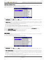
From the CONFIG page, pess [F2] or move the cursor to the left to see the second configuration page, the PARAMETERS
page. Here, the parameter transmitted when selecting a Scene can be configured, as well as the aftertouch (the pressure
on a key when it is completely lowered) responde curve and MIDI message:
VIEW=ALL
VIEW=SINGLE
The following parameters are available:
Vol / Volume: the initial sound volume, set by Control Change 7. When OFF is selected, this Control Change is not
transmitted.
Pan (Pan-Pot): initial stereophonic distribution, set by Control Change 10. When OFF is selected, this Control Change
is not transmitted.
Rev / Reverb: initial reverb level, set by Control Change 91. When OFF is selected, this Control Change is not
transmitted.
Cho / Chorus: initial Chorus level, set by Control Change 91. When OFF is selected, this Control Change is not
transmitted
Note / Note Shift ±: Zone transposition (note shift) in semitones.
Tran / Transpose Enable: enable or disable transposition. Select YES to allow transposition, which can be controlled
by pressing the [TRANSPOSE] button. Select NO to disable.
Aftouch Message / Aftouch: this MIDI message is transmitted when using the aftertouch. It is possible to select:
OFF: none MIDI message transmitted
CH PRESS: Channel Pressure (aftertouch di canale)
CC: Control Change
NRPN: Non Registered Parameter Number
RPN: Registered Parameter Number
PITCH: Pitch Bend
AftCurve: aftertouch response curve. The following options are available:
- NORM: linear curve, the transmitted MIDI value corresponds to the pressure value.
- SOFT 1 e 2: soft curves; curve 1 is the softest.
- HARD 1 e 2: hard curves, curve 1 is the hardest.
EN - 24 User Manual – Checking and modifying a Performance (Info and Edit Mode)
To see other pages under the ZONES section, press the function buttons: [F1], [F2], [F3] or [F4].
Press [EXIT] to return to INFO MODE and EDIT MODE.
Press [INFO] to return to PERFORMANCE MODE if the system is currently in INFO mode. Otherwise, press [EDIT], or
press [EXIT] two times.
To access a different operating mode, press its corresponding button, in the MODE section of the front panel.
NB
Although the parameters that can be configured in the video pages CONFIG and PARAMETERS (except Note \
Note Shift ±, Tran \ Transposition Enable and Aftouch Message / Aftouch and AftCurve) affect the MIDI
messages sent when a Scene is selected, each time the parameter is modified, its MIDI message is transmitted. The
result of parameter adjustments can therefore be experienced in real time, without saving and loading a
Performance. VELOCITY
Press [F3] or move the cursor to the left to visualize the third Zone configuration page. This page is called VELOCITY, and
affects the dynamic response of the keyboard:
VIEW=ALL
VIEW=SINGLE
The available parameters are:
Vel Type: dynamic curve type, can be
- NORM: linear curve, transmitted MIDI value corresponds to the pressure value.
- SOFT: soft curves; curve 1 is the softest.
- HARD: hard curves, curve 1 is the hardest.
- COMP: this curve reaches the medium values very quickly, then the value increase grows slower in a linear way.
- EXP: similar to the COMP curve, but reaches medium and high values more quickly.
- FIXED: fixed curve, the value can be set through the AMOUNT parameter.
- USER: user programmable curve (see next description: ‘‘User programmed dynamic curves").
Amount (unavailable for the LINEAR curve): sets the influence of the selected curve on the dynamic; when the FIXED
curve is selected, it sets the fixed value.
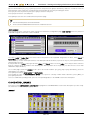
Polarity: curve polarity; can be normal (NORM), or inverted (INVERT). The following images explain the polarities:
Resulting
velocity
Resulting
velocity
Key pressure
Polarity=NORM
Key pressure
Polarity=INVERT
This parameter is useful to create dynamic layers. For example, setting a normal (NORM) polarity for a Zone, and INVERT
for another, the second Zone will be louder when using a low dynamic, while the first Zone will be louder with high
dynamic.
EN - 25
User Manual – Checking and modifying a Performance (Info and Edit Mode)
Lower: the minimum dynamic value accepted; keys pressed with a lower dynamic are not transmitted.
Upper: the maximum dynamic value. keys pressed with a stronger dynamic are not transmitted.
As the Polarity parameter, these two can be used to create dynamic layers. For example, set the same value for the
Lower parameter in a Zone and for the Upper parameter in another. When playing at a low dynamic, only the second
Zone will transmit notes and vice-versa.
The curves can be visualized thanks to the graphs of the Velocity Curve column (in view mode "ALL") or on the right side of
the page (in view mode "SINGLE"). The horizontal x-axis corresponds to key pressure, while the vertical y-axis corresponds
to the transmitted MIDI value.
To see other pages under the ZONES section, press the function buttons: [F1], [F2], [F3] or [F4].
Press [EXIT] to return to INFO MODE and EDIT MODE.
Press [INFO] to return to PERFORMANCE MODE if the system is currently in INFO mode. Otherwise, press [EDIT], or
press [EXIT] two times.
To access a different operating mode, press its corresponding button, in the MODE section of the front panel.
USER PROGRAMMED DYNAMIC CURVES
After selecting a USER dynamic curve, place the cursor on the Velocity Curve graphic and press [ENTER] (in VIEW mode
ALL). The following page will appear::
When VIEW mode is set as SINGLE, after selecting a USER dynamic curve
To access the Edit User Velocity Curve page, place the cursor on the EDIT field and press [ENTER]. To draw a curve,
add and place points as desired.
The Points parameter indicates the currently selected point, while X and Y are the point's coordinates. The slected point
appears as a red dot on the graph; red arrows around the dot show in which directions it can be moved. The first and last
points cannot be moved horizontally. Press [F3] to add a new point, after the selected one:
EN - 26 User Manual – Checking and modifying a Performance (Info and Edit Mode)
Use the arrow buttons [U], [V], [Y] and [Z] to move the point on the graph; alternatively, rotate the encoder to move the
point along the Y axis; rotate the encoder while pressing [SHIFT] to move the point along the X axis.
Press [F1] to select the previous point; press [F2] to select the next point.
Press [F4] to remove the selected point.
Press [EXIT] to save the curve and return to the previous page.
NB
•
•
The first and last points cannot be removed. Points cannot be added before the first one or after the last one. KEY RANGE
Press [F4] or move the cursor to the left to visualize the fourth Zone configuration page, KEY RANGE, where the portion of
keyboard assigned to each Zone can be modified:
VIEW=ALL
VIEW=SINGLE
The value Lower or Lower Key is the lowest note of the portion of the keyboard assigned to the Zone, while Upper or
Upper Key is the highest note.
To select a key, use the normal procedure to enter data (described elsewhere) or press the key on your keyboard with the
[SHIFT] button pressed.
It also possible to set Lower values greater than Upper, and Upper values less than Lower: In this way the Zone continues
from the extreme top to the bottom, thus obtaining two distinct portions of the keyboard (see Zone4 in the screen with
VIEW=ALL depicted above). To see other pages under the ZONES section, press the function buttons: [F1], [F2], [F3] or [F4]; alternatively, press the
arrow buttons [Y] and [Z].
Press [EXIT] to return to INFO MODE and EDIT MODE.
Press [INFO] to return to PERFORMANCE MODE if the system is currently in INFO mode. Otherwise, press [EDIT], or
press [EXIT] two times.
To access a different operating mode, press its corresponding button, in the MODE section of the front panel.
5.6 CONTROL BANKS
Press [F2] in either INFO MODE or EDIT MODE to program the CONTROLLERS section of the front panel (see also chap.
3.3, under the “Control Bank” pragraph).
BANKS
EN - 27
User Manual – Checking and modifying a Performance (Info and Edit Mode)
Here you can find information on the selected Control Bank and on the status of all controls.
On the top of the page there are two fields:
Name: name assigned to the control bank.
Enable: bank status; can be:
ON: bank enabled; press the [BANK 1] ... [BANK 4] buttons to activate/deactivate.
OFF: bank disabled; the [BANK 1] ... [BANK 4] buttons have no effect.
The field on the right shows the currently selected Control Bank.
The page shows in graphic form the current status of all controls; using controls (such as pressing a button, or rotating a
knob) immediately affects the data on this page (see also chap. 4.7).
Buttons appear in yellow if they are set as “on” or in STEP mode (see Knobs, Sliders and Buttons below).
Press [F1] to see information on the next Control Bank.
To see more pages under the CTRL BANKS section, press the function buttons [F1], [F2], [F3] or [F4].
Press [EXIT] to return to INFO MODE and EDIT MODE menus.
Press [INFO] to return to PERFORMANCE MODE if the system is currently in INFO mode. Otherwise, press [EDIT], or
press [EXIT] two times.
To access a different operating mode, press its corresponding button, in the MODE section of the front panel.
KNOBS, SLIDERS and BUTTONS
From the BANKS page, press [F2] or move the cursor to the right to visualize the second configuration page, the KNOBS
page. The knobs [KNOB 1] ... [KNOB 9] can be controlled from here.
Press [F3] or move the cursor to the right to access the SLIDERS page, related to the cursor controls [SLIDER 1] ...
[SLIDER 9].
Press [F4] or move the cursor to the right to access the BUTTONS page, related to the [BUTTON 1] ... [BUTTON 9]
controls.
Press the function buttons [F1], [F2], [F3] or [F4], or move the cursor to the left, to return to the previous pages.
KNOBS
SLIDERS
BUTTONS
Available parameters are:
Type: type of MIDI message transmitted by the control, can be
- OFF: no MIDI message assigned
- CC: Control Change
- NRPN: Non Registered Parameter Number
- RPN: Registered Parameter Number
- PITCH: Pitch Bend
EN - 28 User Manual – Checking and modifying a Performance (Info and Edit Mode)
PROG: Program Change
CH PRESS: Channel Pressure (channel aftertouch)
NOTE: note message (only for buttons)
Message MSB-LSB: this parameter is type-dependent, that is:
CC: Control Change number
NRPN e RPN: MSB and LSB number for Non Registered Parameter Number and Registered Parameter Number
PG: MSB and LSB numbers of Bank Select messages
-
PITCH and CH PRESS messages do not have this parameter.
Min or Off: minimum value, transmitted when,
• a slider is at its lowest
• a knob is rotated counter-clockwise
• a button is not pressed (TOGGLE mode, see MODE parameter), with Led light off (NORMAL mode), or at first
STEP (in STEP mode)
Max or On: maximum value, transmitted when,
a slider is at its highest
a knob is rotated clockwise
a button is pressed (TOGGLE mode), with Led light (NORMAL mode), or at its last STEP (STEP mode)
•
•
•
This is how MIDI messages usually work. However, controls can be used in inverted mode, so that a MIDI messages
ha maximum value when
•
•
•
a slider is at its lowest
a knob is rotated counter-clockwise
a button is not pressed (TOGGLE mode), with Led light off (NORMAL mode), or at first STEP (in STEP mode)
To do so, set the Max parameter to a value lower than the Min parameter.
Value: starting value, transmitted when a Scene is selected, calculated according to the range set by the Min and
Max parameters. This field can be modified also by using the corresponding control. The page visualizes the current
value.
Mode: (only for BUTTONS), indicates the function mode for buttons, can be:
−
−
−
NORMAL: by standard, the value is at minimum. While pressed, the value is at its maximum;
TOGGLE: each time the button is pressed, the value is toggled between maximum and minimum;
STEP: each time the button is pressed, the value is increased or decreased by one unit.
NB
The off - on range of buttons (in STEP mode) assigned to more than one Zone is the shortest of the set ranges. For
example, if the range is set as 0-127 for a Zone and 0 - 100 for another, the actual range of the MIDI messages will be
0-100.
Name: name associated to the panel control. To enter a new name, follow the procedure described at chap. 5.2.
Press [F2] in the KNOBS page to switch to the next knob; rotating a knob automatically opens the page for that particular
knob.
Press [F3] in the SLIDERS page to switch to the next slider; moving a slider automatically opens the page for that particular
slider.
Press [F4] in the BUTTONS page to switch to the next button; pressing a button automatically opens the page for that
particular button.
Press the function buttons [F1], [F2], [F3] and [F4] to switch to a different page of the CTRL BANKS section.
Press [EXIT] to return to INFO MODE and EDIT MODE.
Press [INFO] to return to PERFORMANCE MODE if the system is currently in INFO mode. Otherwise, press [EDIT], or
press [EXIT] two times.
To access a different operating mode, press its corresponding button, in the MODE section of the front panel.
EN - 29
User Manual – Checking and modifying a Performance (Info and Edit Mode)
5.7 WHEELS AND PEDALS
Press [F3] in INFO MODE and EDIT MODE to access the configuration pages about wheels and pedals (see also chap.
3.3 paragraphs “Pedals” and “Wheels”). These pages are almost identical and will be explained together.
PEDALS
WHEELS
The first page deals with the pedals connected to the [PEDAL 1] ... [PEDAL 8] connectors on the rear panel.
Press [F4] or move the cursor to the right to show the configuration page for wheels ([WHEEL 1], [WHEEL 2] and [WHEEL
3] for K4 models). Here, press [F3] or move the cursor to the left to return to the pedals page.
Press [F3] while on the PEDALS page to select the next pedal.
Press [F4] while on the WHEELS page to select the next wheel.
Pressing a pedal or moving a wheel will open immediately the configuration page for that control.
Available parameters are:
Type: The type of MIDI message sent or the function performed by the control,
- OFF: no MIDI message assigned
- CC: Control Change
- NRPN: Non Registered Parameter Number
- RPN: Registered Parameter Number
- PITCH: Pitch Bend
- PROG: Program Change
- CH PRESS: Channel Pressure (channel aftertouch)
- NOTE: note message (only for Switch pedals)
- ZONE: activate / deactivate the Zone
If a system function has been assigned to a pedal or wheel (see chap. 7.5), this column will show the title ‘‘SYSTEM’’.
To disable system function for a Zone, just set the parameter as OFF.
NB
•
For the switch type pedals, the ZONE function is not performed if the operating mode is STEP (see parameter
Mode). For the continuous pedals, functions NOTES and ZONE are not executed. •
Message MSB-LSB: this parameter is Type dependent, can be:
CC: Control Change number;
NRPN e RPN: MSB and LSB numbers for Non Registered Parameter Number and Registered Parameter Number;
PG: MSB and LSB numbers of Bank Select messages.
-
PITCH and CH PRESS messages do not require this parameter.
Min: minimum value, transmitted when:
• an expression pedal or wheel is at its lowest point
• a switch pedal is not pressed (TOGGLE mode, see Mode parameter), is off (NORMAL mode), or at its first step
(STEP mode)
the message value can never go below its minimum.
Max: maximum value transmitted when,
an expression pedal or wheel is at its highest point;
a switch pedal is pressed (TOGGLE mode), is on (NORMAL mode), or at its last step (STEP mode);
•
•
EN - 30 User Manual – Checking and modifying a Performance (Info and Edit Mode)
the message value can never be higher than its maximum.
Normally, the MIDI message assigned to a control is transmitted with its minimum value when the control is at its
lowest, as explained before. However, controls can be used in inverted mode, so that the maximum value is
transmitted when,
• an expression pedal or wheel is at its lowest point
• a switch pedal is not pressed (TOGGLE mode, see Mode parameter), is off (NORMAL mode), or at its first step
(STEP mode)
To do so, set the Max parameter to a lower value than the Min parameter.
Value: starting value, transmitted when a Scene is selected, calculated according to the range (set by Min and Max).
This field can be modified also by moving the control itself. The display will show the numerical value and a graphical
representation of that value.
Mode: (only for PEDALS), indicated the pedals function mode; can be
CONTINUOUS: continuous control. This mode is automatically selected by the instrument when the pedal is
configured as CONTINUOUS under the SETUP \ PEDALS page in SYSTEM mode.
NORMAL: maximum value is transmitted when the pedal is pressed; minimum value is transmitted when the pedal
is released. This mode can be selected when the pedal is configured as SWITCH under the SETUP \ PEDALS
page of the SYSTEM mode.
TOGGLE: pressing the pedal toggles between minimum and maximum value. This mode can be selected when a
pedal is configured as SWITCH under the SETUP \ PEDALS page of the SYSTEM mode.
STEP: the value increases by one unit each time the pedal is pressed. This mode can be selected when the pedal
is configured as SWITCH under the SETUP \ PEDALS page of the SYSTEM mode.
NB
The off - on range of pedals (in STEP mode) assigned to more than one Zone is the shortest of the set ranges. For
example, if the range is set as 0-127 for a Zone and 0 - 100 for another, the actual range of the MIDI messages will be
0-100.
Name: name associated to the panel control. To enter a name, follow the procedure described at chap. 5.2.
Press [F1] while on the PEDALS page to access the SETUP \ PEDALS page of the SYSTEM mode, to configure and
calibrate pedals. System function can be assigned from here.
Press [F1] while on the WHEEL page to access the SETUP \ WHEELS under the SYSTEM mode, to configure and
calibrate wheels. System functions can be assigned here.
These configuration pages for wheels and pedals are described at chap. 7.5.
To see the other pages of the PEDALS+WHEELS section, press the function buttons [F1], [F2], [F3] and [F4].
Press [EXIT] to return to INFO MODE and EDIT MODE.
Press [INFO] to return to PERFORMANCE MODE if the system is currently in INFO mode. Otherwise, press [EDIT], or
press [EXIT] two times.
To access a different operating mode, press its corresponding button, in the MODE section of the front panel.
5.8 ADDITIONAL MESSAGES
Press [F1] on the second page of the INFO MODE and EDIT MODE menus to access the programming pages. Here, the
messages sent when a Scene is recalled (see also chap 3.3, paragraph "Messagges") and input maps ("Input Map"
paragraph) can be programmed.
EN - 31
User Manual – Checking and modifying a Performance (Info and Edit Mode)
Here a maximum of 8 MIDI messages can be programmed. These messages will be transmitted when the Scene is
selected, through the port and channel set by the Scene. The 8 messages appear in the 8 rows of the table.
The Output column shows the outputs through which the message is transmitted. The Message column corresponds to
the MIDI message and the Ch column indicates the MIDI channel.
NB
The REMOVE and EDIT functions can be recalled by pressing the function buttons [F2] and [F3]; they can be used
only if the cursor is placed on a row in which a message is currently present. To insert a new message, place the cursor on an empty row, then press [F1]:
The available fields are:
Messagge Type: the transmitted message type,
- CC: Control Change
- NRPN: Non Registered Parameter Number
- RPN: Registered Parameter Number
- PROG: Program Change
- SYSEX: System Exclusive
Send Mode: when to transmit the message, after a Scene has been recalled.
- POST: after the Scene data package
- PRE: before the Scene data package
This parameter is particularly useful to adapt to the type and function of a message. For a message that sets a global
function of the receiving device, such as single- or multi-sound mode, the message must be usually transmitted before
the sound configration data (set by the Scene). If the message is a sound control parameter, and the sound is
regulated by the Scene, the transmission must occur after the Scene data package, or the message will not work.
Output: the MIDI message transmission port. For Zones, the output is the same set by the Zone; otherwise, the name
printed beside the output port will be visualized, or the name of a Virtual Instrument. Virtual Instruments can be created
through the DEVICES function under the SYSTEM mode. Virtual Instruments can be disabled, but they are still
assigned to the Zone. When disabled, however, they will not send any MIDI message. Disabled Instruments appear in
grey.
NOTE
When the selected Output is a Zone, the message will always be transmitte, regardless of the Zone status (active,
inactive, disabled.
Channel: MIDI channel.
The next two fields are message dependent.
If the message is a Control Change, they are:
Control: Control Change number.
Value: Control Change value.
In the case of NRPN and RPN they are:
NRPN or RPN MSB: the message number of the NRPN or RPN MSB.
NRPN or RPN LSB: the message number of NRPN or RPN LSB.
EN - 32 User Manual – Checking and modifying a Performance (Info and Edit Mode)
Data Entry: the value NRPN or RPN.
If the message is a Program Change, they are:
Bank MSB: Bank Select MSB message number. If this is not necessary, select “OFF”.
Bank LSB: Bank Select LSB message number. If this is not necessary, select “OFF”.
Name: name of the sound bank selected by the Bank MSB and LSB messages. This field only works if the output is
Virtual Instrument, and if Program Bank Tables have been properly created for that Instrument through the PROGRAM
BANKS function under the SYSTEM mode, and if name have been assigned.
Program Change: Program Change MIDI message, sent when the Scene is selected, to the MIDI port and channel
assigned to that Zone. This message selects a sound. If this message is unnecessary, select “OFF”. If the port is a
Virtual Instrument for which Program Bank Tables have been created (through the PROGRAM BANKS function under
the SYSTEM mode) and names have been assigned to the Program Change messages, these names appear beside
the Program Change number. Otherwise, a line of dashes will appear ("---").
If a message is System Exclusive:
System Exclusive Data: a System Exclusive message can be composed here. To enter the message, use the
encoder or the KEYPAD section buttons, then press the arrow buttons [Y] and [Z] to move the cursor among bytes.
Using the KYEPAD buttons opens the following page (see next page):
Press [F1] to enter the opening SysEx byte "F0" and [F2] to enter the close message byte "F7".
Press [F3] to erase all data.
Press [F4] or [ENTER] to confirm.
Once the MIDI message has been entered, press [F3] or [EXIT] to cancel the performed programming; press [F4] or
[ENTER] to confirm. In any case, the display shows the initializing messages.
Now, press [F2] to delete a selected message, or [F3] to modify the message, following the procedure described before.
Press [EXIT] to return to INFO MODE and EDIT MODE.
Press [INFO] to return to PERFORMANCE MODE if the system is currently in INFO mode. Otherwise, press [EDIT], or
press [EXIT] two times.
To access a different operating mode, press its corresponding button, in the MODE section of the front panel.
5.9 MIDI INPUT MAPS
Press [F4] on INFO MODE and EDIT MODE to access the second page, then press [F2] to switch to the input maps page
(see also chap. 3.3, paragraph “Input Map”). These maps (up to 8) can be used to transmit the data received from the
MIDI inputs to the outputs; ports and channels are defined here, and MIDI filters can be applied to the passing data. This is
the configuration page:
EN - 33
User Manual – Checking and modifying a Performance (Info and Edit Mode)
Each row corresponds to an available map. The Input column indicates the MIDI input of the map, while the input channel
can be found in the first Ch column.
The Output column shows the Zone or the MIDI output port to which the ingoing data is transmitted, while the second Ch
column shows the output channel. To program a new map, select an empty row and press [F1]:
The following fields are available:
Input: the MIDI input port; data incoming from this port will be sent to an output.
In Channel: the MIDI input channel, related to the input port selected through the Input parameter. In ANY mode, all
channels are accepted: this mode is particularly useful when you want each received data to be redirected to a single
channel, set by the parameter Out Channel.
Output: the MIDI output port, to which the incoming data is transmitted. Set the input port and channel through the
Input and In Channel parameters. For Zones, the output is the same set by the Zone; otherwise, the name printed
beside the output port will be visualized, or the name of a Virtual Instrument. Virtual Instruments can be created
through the DEVICES function under the SYSTEM mode. Virtual Instruments can be disabled, but they are still
assigned to the Zone. When disabled, however, they will not send any MIDI message. Disabled Instruments appear in
grey.
NOTE
When the selected Output is a Zone, the data received from the MIDI port are always transmitted, regardless of the
Zone status (active, inactive, disabled).
Out Channel: MIDI output channel, related to the output port select through the Output parameter. Incoming data
from the Input port and In Channel is sent here. If you want the messages are not redirected to a MIDI channel other
than the one on which they are received, select the mode: ANY.
Filters: MIDI filters to prevent redirection of the following MIDI messages:
Note: note
Prog: Program Change
Ctrl: Control Change
SYSEX: System Exclusive
Sync: Start, Stop, Continue, MIDI Clock, MIDI Time Code, Song Position Pointer, Song Select
After the input map has been set, press [F3] or [EXIT] to cancel; press [F4] or [ENTER] to confirm the configuration. In any
case, the display shows the maps list.
From the same page, press [F2] to delete the selected map, or [F3] to modify it, following the procedure described above.
Press [EXIT] to return to INFO MODE and EDIT MODE.
Press [INFO] to return to PERFORMANCE MODE if the system is currently in INFO mode. Otherwise, press [EDIT], or
press [EXIT] two times.
To access a different operating mode, press its corresponding button, in the MODE section of the front panel.
EN - 34 User Manual – Sequence of Performances (Chain Mode)
6. SEQUENCE OF PERFORMANCES (CHAIN MODE)
6.1 FOREWORD ON CHAIN MODE
The term "Chain" refers to a sequence of Performances alternative to the standard sequence P001 - P128. Chains can be
selected by the user under PERFORMANCE MODE. The system supports up to 10 programmable Chains, that can be
recalled at any moment by selecting the CHAIN mode. A Chain consist of a maximum of 128 steps, that is, 128 locations
associated to a Performance. The normal sequence of Performances is P001, P002, P003, etc. A Chain can associate
Performance P013 to Step 1, P004 to Step 2, P054 to Step 3 and so on. When recalled, such a Chain will recall
Performances according to the desired order: P013, P004, P054. The same Performance can be associated to more than
one Step, making it easier to use the same Performance more than once, without scrolling.
6.2 SELECTING A CHAIN
To recall a Chain, first press the [CHAIN] button in the MODE section of the front panel. The following page will appear:
Press [F1] to navigate Chains.
The Chain Name field indicates the list name; it can be modified when programming a Chain (see chap. 6.3).
The Chain Step list shows all steps of the Chain, and the Performance assigned to each step. Empty steps are visualized
as a string of dashes (“----------------“).
To scroll through steps, press [Z] to place the cursor on the list, then use the arrow buttons [U] and [V] to scroll.
To activate the currently selected list, place the cursor on the CHAIN MODE field and select ON. To disable the CHAIN
Mode select OFF.
Once you see the list that you want to activate in the CHAIN MODE field, select ON. To turn off the CHAIN mode, select
OFF.
Press [CHAIN] or [EXIT] to return to the PERFORANCE MODE page:
On the top left there is a field called CHAIN STEP, indicating the currently selected step. This field also reminds that
CHAIN MODE is active, and that the sequence of Performances is different from P001 – P128.
The first Performance of a Chain is not loaded yet, however, not to alter the current situation. To load the first step of a
Chain, press [SHIFT] and [DEC] at the same time.
To select the next step, press [SHIFT] and [INC] at the same time, performing the CHAIN < function.
To select the previous step, press [SHIFT] and [DEC] at the same time, performing the CHAIN < function.
Even though the Chain is active, it is possible to follow the normal sequence (P001 - P128) by following the standard
procedure (Encoder, KEYPAD buttons, [DEC] and [INC] buttons).
To leave CHAIN MODE, press [CHAIN] and set the Chain Enable parameter as OFF.
EN - 35
User Manual – Sequence of Performances (Chain Mode)
6.3 PROGRAMMING A CHAIN
From any page, press the [CHAIN] button to access the following page:
Should the Chain be already programmed, the Chain Steps list shows the assigned steps. Empty steps appear as a string
of dashes (“----------------“). Place the cursor on the field by pressing the [Z] button. The page will appear as following:
Use the arrow buttons [U] and [V] to scroll the list. The same buttons used with the [SHIFT] button allow you to skip ten
steps.
To insert a new Performance, use the DATA ENTRY or KEY PAD controls.
To insert a new step, after the selected one, press [F3].
To remove the selected step, press [F4].
To skip to a different step without scrolling, press [F2]; the following page appears:
Now enter the number of the step using the KEYPAD buttons.
Press [F3] to delete data.
Press [F1] to select the first step, or [F2] to select the last available step.
Press [F4] or [ENTER] to confirm the selected step, or [EXIT] to abort.
While on CHAIN MODE, place the cursor on the Chain Name field and press [ENTER] to assign a name to the Chain. To
enter a new name, follow the procedure described at chap. 5.2.
Press [CHAIN] or [EXIT] to return to PERFORMANCE MODE.
To access a different operating mode, press its corresponding button, in the MODE section of the front panel.
NB
Changes to one or more Chains are automatically saved. EN - 36 User Manual – General instrument settings (System Mode)
7. GENERAL INSTRUMENT SETTINGS
(SYSTEM MODE)
7.1 FOREWORD ON SYSTEM MODE
Pressing the [SYSTEM] button on the front panel MODE section, you can access the System MIDI settings, creation and/or
modification of Virtual Instruments, allocation of system functions to the pedals, wheel and aftertouch, and other functions
utilities including customization and upgrade the operating system of the instrument.
The first page is called SYSTEM MODE; it is a selection menu, from which the specific functions can be accessed:
All function are grouped into four section; to select a section, press the corresponding function button:
[F1]: GLOBAL section, which contains the System MIDI settings and collects the customization settings of the
instrument.
[F2]: INSTRUMENTS section, containing programming functions for Virtual Instruments.
[F3]: SETUP section, where pedals and wheels can be calibrated and assigned system functions; keyboard aftertouch
can also be calibrated here, and a remote external sequencer can be configured in this section.
[F4]: UTILITY section, containing information on the instrument; all settings and Performances can be saved and
loaded here; Factory Reset function.
Press [SYSTEM] or [EXIT] to return to PERFORMANCE MODE, or any other MODE button to access the corresponding
operating mode.
7.2 SYSTEM MIDI AND PREFERENCES
Pressing [F1] in the SYSTEM MODE screen, you have access to the following sub-menus:
Place the cursor on one of the fields and press [ENTER] to recall the corresponding functions:
MIDI COMMON: collects the Local Control setting and selection of ports and MIDI channels for receiving and sending
messages to the system.
PREFERENCES: customization functions of the instrument.
EN - 37
User Manual – General instrument settings (System Mode)
MIDI COMMON
To set the System MIDI messages, place the cursor on the MIDI COMMON field and press [ENTER]:
You can set:
Local Control: when set to ON, the keyboard notes and messages assigned to the panel controls and pedals are
transmitted to the output ports as well as set into the currently selected Performance. When OFF is selected, the
transmission ports set in the Performance are disabled.
Input Port: select the port receiving system MIDI messages, transmitted from an external device that received them
from the port you have set with the parameter Output Port and retransmitted via its MIDI Thru function or MIDI Echo
(which then needs to be activated). When OFF is selected, the receipt of such messages is disabled.
Input Channel: Selects the MIDI channel on which to receive system MIDI messages. In order to perform the
messages received, the channel must be the same as the external device that received them and retransmitted via its
MIDI Thru function or MIDI Echo.
Input Filters: if any MIDI filters if you want to avoid receiving the following system MIDI messages:
Note: notes
Prog: Program Changes
Ctrl: Control Changes
Output Port: Select the port to send System MIDI messages. If you select OFF, the transmission of such messages is
disabled.
Output Channel: select the MIDI channel on which to transmit System MIDI messages.
Output Filters: if any MIDI filters if you want to avoid the transmission of the following MIDI messages to the system:
Note: notes
Prog: Program Changes
Ctrl: Control Changes
For more information about system messages and Local Control refer to par. 3.3 - Internal Structure – MIDI Common and
10.2 for insight into System MIDI messages.
With Local Control set to OFF, the screen PERFORMANCE MODE this informational message is displayed:
indicating that the MIDI data is not sent over the channels and ports set in the Zone.
NB
If the system port (Output Port) is active, the instrument transmits the events of keyboards and controls even if the
Local Control is set to OFF. EN - 38 User Manual – General instrument settings (System Mode)
7.3 INSTRUMENT PREFERENCES
Customisation settings are grouped in this section, affecting the general functions of K4 / K5 and display graphics. To
access this section, press [F1] from SYSTEM MODE:
Now press the arrow button [V] to move the cursor on the fields below, and to scroll down. Press [U] to select the field
above, and to scroll up.
Available parameters are:
Enable Graphic Animations: activate (YES) or deactivate (NO) graphic animations for video pages.
Set Brightness Value: set display brightness.
Set Screen Theme: selection of graphic themes of the screens.
Confirm Loading by Pressing [ENTER] Key: choose whether a selected Performance is immediately active (NO) or
is activated only after pressing [ENTER] (YES).
Enable Controller Popups: select YES to automatically load the control page (see chap. 4.7) each time a slider,
button or knob is used.
Press [EXIT] to return to SYSTEM MODE.
Press [SYSTEM] or [EXIT] two times, to return to PERFORMANCE MODE.
Press a MODE button to access the corresponding operating mode.
7.4 PROGRAMMING VIRTUAL INSTRUMENTS
As described in chapter 3.3 under the “Zone” paragraph, K4 / K5 offers 10 Virtual Instrument tables, containing names for
sound and controls of external devices, so as to allow an easier programming of Zones.
DEVICES
From SYSTEM MODE press [F2] to access the following page:
Here the general features of a Virtual Instrument can be defined. Available parameters are:
Device Name: name of the connected MIDI device. When selecting an output port for a Zone (Output column of the
ZONE \ CONFIG page, in EDIT MODE), this name will appear on screen. To assign a name, select the field and press
[ENTER]. To enter a name, follow the procedure described at chap. 5.2.
Enable: enable (select YES) or disable (NO) a Virtual Instrument. An enabled instrument appear on the Output
column of the ZONE \ CONFIG page in EDIT MODE.
Port: MIDI output port, to which the Virtual Instrument is connected.
EN - 39
User Manual – General instrument settings (System Mode)
Channels: MIDI channels enabled to transmit data. To modify, place the cursor on a channel number and press [INC]
to enable or [DEC] to disable.
Press [F1] to select the next Virtual Instrument.
To see the other INSTRUMENTS pages, press the function buttons: [F1], [F2], [F3] or [F4].
To return to SYSTEM MODE press [EXIT].
To return to PERFORMANCE MODE press [SYSTEM] or [EXIT] two times.
Press a MODE button to access the corresponding operating mode.
PROGRAM BANKS
Once the Virtual Instrument has been selected and configured in the DEVICES page, a sound bank can be programmed.
Programming a sound bank allows to enter the sound list(s) into the receiving instrument. To do so, press [F2] or move the
cursor to the right:
In this page sound lists to a maximum of 8 can be programmed; these lists correspond to the sound banks of the external
device. Available parameters are:
Table Name: sound bank name; it will be shown when selecting Bank Select MSB and LSB messages (Bank MSB –
LSB column, ZONE \ CONFIG video page in EDIT MODE, see chap. 5.5). To enter a new name, place the cursor on
this field, then press [ENTER]; follow the procedure described at chap. 5.2.
Table Enable: enable (YES) or disable (NO) the sound bank; enabled banks appear in the Bank MSB – LSB and
Program Change columns on the ZONE \ CONFIG page, in EDIT and INFO MODE (see chap. 5.5).
Program Bank MSB and Program Bank LSB: MIDI MIDI Bank Select MSB and LSB number; when these messages
are received, the external device selects the sound bank.
Program Name: names of the Program Change, which will be displayed in the selection of Program Change
messages (Program Change column on the screen ZONE \ CONFIG in EDIT MODE, see par. 5.5), assigned on the
basis of sounds and/or programs in the external device. The numbers that appear in this field correspond to the
Program Change that in the receiving instrument are assigned to the sound/program. Read the user manual to see the
link between Program Change and name, then enter the same link here by following this procedure:
1. press [Z] to place the cursor on the table,
2. press the arrow buttons [U] and [V] to scroll through Program Changes and place the cursor on the desired one.
The same buttons used with the [SHIFT] button allow you to skip ten steps.
3. press [ENTER] and follow the procedure described at chapter 5.2.
Press [F2] to select the next sound bank and visualize its information.
Press the function buttons [F1], [F2], [F3] and [F4] to access the other video pages of the INSTRUMENTS section.
To return to SYSTEM MODE press [EXIT].
To return to PERFORMANCE MODE press [SYSTEM] or [EXIT] two times.
Press a MODE button to access the corresponding operating mode.
EN - 40 User Manual – General instrument settings (System Mode)
CONTROL CHANGE TABLE
Virtual Instruments also allow Control Change tables, containing names assigned to Control Change messages, so as to
recognize the parameters of external devices through proper names.
To do so, press [F3] or move the cursor to the left. The following page will appear:
the following parameters are available:
Table Enable: enable (YES) or disable (NO) the Control Change table; when enabled, the assigned names appear on
the Message MSB – LSB column of the control pages.
Control Name: name of controls/parameters of the external device. Control Change numbers used by the receiving
instruments appear in this table. Read the user manual of the device to see what name is assigned to each Control
Change, then enter the names in the table following the procedure:
1. press [Z] to place the cursor on the table,
2. use the arrow buttons [U] and [V] to scroll the table and place the cursor on the desired Control Change. The
same buttons used with the [SHIFT] button allow you to skip ten steps.
3. press [ENTER] and enter the name, following the procedure described at chapter 5.2.
Press the function buttons [F1], [F2], [F3] and [F4] to access the other video pages of the INSTRUMENTS section.
To return to SYSTEM MODE, press [EXIT].
To return to PERFORMANCE MODE, press [SYSTEM] or [EXIT] two times.
Press a MODE button to access the corresponding operating mode.
NRPN TABLE
In addition to Control Changes, a Virtual Instrument can also associate names to NRPN messages, so as to make them
more easily recognizable while setting parameters.
Press [F4] or move the cursor to the left. The following page will appear:
Available parameters are:
Table Enable: enable (YES) or disable (NO) the NRPN table. When enabled, the assigned names appear under the
Message MSB – LSB column of the control pages.
MSB LSN NRPN Name: names of the controls/parameters available in the external device. The number on the list are
the two NRPN MSB and LSB messages that the receiving instrument uses to adjust controls. Read the user manual of
the device to see what name is assigned to each Control Change, then enter the names in the table following the
procedure:
1. Press the [Z] button to place the cursor on the table,
2. use the arrow buttons [Y], [Z], [U] and [V] to select the MSN and LSB values and define their NRPN. You can
also use the [U] and [V] with [SHIFT] key to jump 10 positions.
EN - 41
User Manual – General instrument settings (System Mode)
3. press the [Z] button to place the cursor on a parameter's name,
4. press [ENTER]; to enter a new name, follow the procedure described at chapter 5.2.
Press the function buttons [F1], [F2], [F3] and [F4] to access the other video pages of the INSTRUMENTS section.
To return to SYSTEM MODE, press [EXIT].
To return to PERFORMANCE MODE, press [SYSTEM] or [EXIT] two times.
Press a MODE button to access the corresponding operating mode.
7.5 CONFIGURATING SYSTEM CONTROLS
Press the function button [F3] while in SYSTEM MODE to access calibration and programming options for pedals, wheels,
keyboard aftertouch and remote sequencer.
PEDALS
The first configuration page affects the pedals connected to the Jack PEDALS connectors on the rear panel:
Available parameters are:
Pedal Type: this parameter sets the type of pedal connected to the instrument. Select CONTINUOUS for continuous
control (expression) pedals; select SWITCH for foot-switch pedals.
Range Calibration (only for Pedal Type = CONTINUOUS): pedal range calibration, see description below.
Pedal Polarity (only for Pedal Type = SWITCH): pedal polarity, can be normal or inverted. For normal use, set the
polarity so that the VALUE polarity is set as 0% when the pedal is not pressed, and 100% when the pedal is pressed.
Select “AUTO” to have the system check automatically the polarity when switching on.
NB
•
•
If Pedal Polarity is set in AUTO mode, connect the pedals only while the instrument is switched off. To access this page, you can also press [F1] from the PEDALS page in EDIT MODE.
VALUE: read-only parameter, indicating the pedal position, so as to allow calibration. Minimum position (or "off"
position, for foot-switch pedals) should always be 0%. Maximum position (or "on" position, for foot-switch pedals)
should always correspond to 100% value. If not so, calibrate the pedal or set the right polarity.
System Function: assign a system function to the pedal. System function are those functions that are not saved into
Scene, and therefore remain the same whatever Scene or Performance is currently selected.
Available system functions are:
- OFF: no function assigned
- MODULATION WHEEL (CC 1): Control Change message n.1 (modulation)
- BREATH CONTROLLER (CC 2): Control Change message n.2 (breath controller)
- FOOT CONTROLLER (CC 4): Control Change message n.4 (foot controller)
- CHANNEL VOLUME (CC 7): Control Change message n.7 (channel volume)
- BALANCE (CC 8): Control Change message n.8 (balance)
- PAN (CC 10): Control Change message n.10 (stereophonic distribution, or panning)
- EXPRESSION (CC 11): Control Change message n.11 (expression)
- SUSTAIN PEDAL (CC 64): Control Change message n.64 (Sustain/Damper pedal)
- SOSTENUTO (CC 66): Control Change message n.64 (Sostenuto)
- SOFT (CC 67): Control Change message n.67 (Soft pedal)
EN - 42 User Manual – General instrument settings (System Mode)
-
LEGATO PEDAL (CC 68): Control Change message n.68 (Legato pedal)
REVEREB SEND (CC 91): Control Change message n.91 (reverb send effect)
CHORUS SEND (CC 93): Control Change message n.93 (chorus send effect)
CHANNEL PRESSURE: channel Aftertouch message
PITCH WHEEL: Pitch Bend message
MASTER VOLUME (GM): System Exclusive message Master Volume GM (general volume)
MASTER PAN (GM): System Exclusive message Master Pan GM (panning)
MASTER FINE TUNING (GM): System Exclusive message Master Fine Tunig GM (fine tuning)
MASTER COARSE TUNING (GM): System Exclusive message Master Coarse Tuning GM (tuning range)
PERFORMANCE INCREMENT: select next Performance
PERFORMANCE DECREMENT: select previous Performance
SCENE INCREMENT: select next Scene
SCENE DECREMENT: select previous Scene
SEQUENCER REMOTE REWIND: rewind message, as when pressing the [] button (for message type
selection, see ‘‘SEQUENCER REMOTE’’ in this paragraph)
SEQUENCER REMOTE FORWARD: fast forward message, as when pressing the [] button (for message type
selection, see ‘‘SEQUENCER REMOTE’’ in this paragraph)
SEQUENCER REMOTE STOP: stop message, as when pressing the [] button (for message type selection, see
‘‘SEQUENCER REMOTE’’ in this paragraph)
SEQUENCER REMOTE PLAY: play message, as when pressing the [] button (for message type selection, see
‘‘SEQUENCER REMOTE’’ in this paragraph)
SEQUENCER REMOTE RECORD: record message, as when pressing the [ ] button (for message type
selection, see ‘‘SEQUENCER REMOTE’’ in this paragraph)
To select functions, use the encoder, the [DEC] and [INC] buttons, or press [ENTER] to open the function list.
Press [F1] to select the next pedal and visualize its information. When a pedal is pressed, its configuration page appears
on the display, as if it were selected through the console.
Press the function buttons [F1], [F2], [F3] and [F4] to access the other video pages of the SETUP section.
To return to SYSTEM MODE, press [EXIT].
To return to PERFORMANCE MODE, press [SYSTEM] or [EXIT] two times.
Press a MODE button to access the corresponding operating mode.
NB
A system function overrides Scene functions. To remind you of this, in the EDIT MODE / PEDALS+WHEELS page
(see chapter 5.7) the Type column says “SYSTEM”. WHEELS
Press [F2] to access the programming and calibration functions for [WHEEL 1], [WHEEL 2] and [WHEEL 3] (in K4 models):
Available parameters are:
Pedal Type: this parameter indicates whether the wheel has is centred (that is, always returns to its central position)
like (la [WHEEL 1]), or is a free wheel, like [WHEEL 2] and [WHEEL 3].
Range Calibration: wheel calibration function (described below).
VALUE: read-only parameter, indicating the current position of the wheel; it is used for calibration. Minimum value
(downwards) should always be 0%, while maximum value (upwards) should be 100%. If not so, perform a calibration.
EN - 43
User Manual – General instrument settings (System Mode)
System Function: assign a system function to the wheel. A system function is a special function which is not saved
into Scenes, and therefore is always active and overrides Scene and Performance Settings.
Wheels can be assigned the same function of pedals (see the “Pedals” paragraph above n this chapter), except for
PERFORMANCE INCREMENT, PERFORMANCE DECREMENT, SCENE INCREMENT, SCENE DECREMENT,
SEQUENCER REMOTE REWIND, SEQUENCER REMOTE FORWARD, SEQUENCER REMOTE STOP, SEQUENCER
REMOTE PLAY, SEQUENCER REMOTE RECORD.
To select a function, use the encoder, the [DEC] and [INC] buttons or press [ENTER] to open a list of the available
functions.
Press [F2] to select the next wheel and visualize its information. Moving a wheel will select it and automatically open its
page.
Press the function buttons [F1], [F2], [F3] and [F4] to access the other video pages of the SETUP section.
To return to SYSTEM MODE, press [EXIT].
To return to PERFORMANCE MODE, press [SYSTEM] or [EXIT] two times.
Press a MODE button to access the corresponding operating mode.
NB
•
•
When a system function is selected, Scene functions are overridden. To underline this, the Type column of the
EDIT MODE \ PEDALS+WHEELS page (see chap. 5.7) says “SYSTEM”.
An alternative way to access this page is pressing [F1] while on the WHEELS page in EDIT MODE.
AFTERTOUCH
Press [F3] to access the aftertouch calibration page:
Available parameters are:
Range Calibration: aftertouch range calibration (described below).
VALUE: read-only parameter, indicating the current aftertouch value; it is used for calibration. Minimum value (mildest
pressure) should always be 0%, while maximum value (strongest pressure on the key) should be 100%. If not so,
perform a calibration.
System Function: assign a system function to the aftertouch. A system function is a special function which is not
saved into Scenes, and therefore is always active and overrides Scene and Performance Settings.
Available system functions are: OFF, CHANNEL PRESSURE, MODULATION WHEEL, BREATH CONTROLLER.
To select a function, use the encoder, the [DEC] and [INC] buttons or press [ENTER] to open a list of the available
functions.
Press the function buttons [F1], [F2], [F3] and [F4] to access the other video pages of the SETUP section.
To return to SYSTEM MODE, press [EXIT].
To return to PERFORMANCE MODE, press [SYSTEM] or [EXIT] two times.
Press a MODE button to access the corresponding operating mode.
EN - 44 User Manual – General instrument settings (System Mode)
CALIBRATING PEDALS, WHEELS AND AFTERTOUCH
If the VALUE field for one of the controls described before cannot reach the values 0% and 100%, the said control must be
calibrated. To do so, place the cursor on the RUN field of the Range Calibration parameter and press [ENTER]:
1. Place the control to its minimum position and press [ENTER].
When calibrating the aftertouch, press the key completely then release it.
2. When calibrating [WHEEL 1], leave it in central position and press [ENTER].
3. Place the control to its maximum position and press [ENTER].
When calibrating the aftertouch, press the key completely.
4. Press [ENTER] to save the new calibration.
Press [EXIT] at any stage to abort the procedure.
NB
The aftertouch sensor is monophonic (channel aftertouch), and therefore it can be calibrated by pressing only one key. SEQUENCER REMOTE
As described in chapter 2.1, point 15, K4 / K5 can control external DAW (Digital Audio Workstation) devices and
applications to play, record or select songs by pressing the SEQUENCER REMOTE buttons on the front panel. There are
two types of remote control MIDI messages for DAW applications: MIDI Machine Control (MMC) or Control Change (CC).
Read the user manual of the applications to see which messages can be used.
Press [F4] while in the SETUP page of SYSTEM mode to access the configuration page for these buttons:
Available parameters are:
Transport Control Mode: MIDI message type, can be:
- OFF: no message sent
- MMC: MIDI Machine Control
[]: F0 7F 7F 06 05 F7
[]: F0 7F 7F 06 04 F7
[]: F0 7F 7F 06 01 F7
[]: F0 7F 7F 06 02 F7
[ ]: F0 7F 7F 06 06 F7
-
CC: Control Change
[]: CC 115
[]: CC 116
[]: CC 117
[]: CC 118
[ ]: CC 119
EN - 45
User Manual – General instrument settings (System Mode)
Transport Control Output: rear panel connector, through which the MIDI messages are sent.
Press the function buttons [F1], [F2], [F3] and [F4] to access the other video pages of the SETUP section.
To return to SYSTEM MODE, press [EXIT].
To return to PERFORMANCE MODE, press [SYSTEM] or [EXIT] two times.
Press a MODE button to access the corresponding operating mode.
7.6 SYSTEM UTILITIES, UPDATE AND FACTORY RESET
Press [F4] while in SYSTEM MODE to access the utilities page. Here you can check tu current firmware release, update
the operating system, check the free space in the internal memory, save and load instrument configuration, or restore the
factory settings. The following page will appear:
Place the cursor on one of the fields and press [ENTER] to recall the corresponding functions:
INFORMATION: information on the instrument model and the current operating system release; update the operating system.
BACKUP: save a backup copy of the instrument's setting to the internal memory or an external USB drive.
RESTORE: load instrument settings (created through the BACKUP function) from the internal memory or an external
USB drive.
FACTORY RESET: reset the instrument's factory settings.
Press [EXIT] to return to SYSTEM MODE.
Press [SYSTEM] or [EXIT] two times to return to PERFORMANCE MODE.
Press a MODE button to access the corresponding operating mode.
INFORMATION and UPDATING THE OPERATING SYSTEM
Use this function to access general information on the instrument or to update the operating system. Place the cursor on
the INFORMATION field then press [ENTER] to open the information pop-up window:
This window contains information on:
MODEL: the model, can be:
K4 GW: K4 with Physis EX sound board and wooden graduated Hammer Action keyboard, Ivory Feel,
K4 EX: K4 with Physis EX sound board and Hammer Action keyboard
K4: K4 without Physis EX sound board, Hammer Action keyboard
K5 EX: K5 with Physis EX sound board and Hammer Action keyboard
K5: K5 without Physis EX sound board, Hammer Action keyboard
FIRMWARE: current firmware release.
EN - 46 User Manual – General instrument settings (System Mode)
FREE SPACE: free space on the internal memory.
Press [EXIT] or [F3] to go back to the previous page.
Each time an update is release (.kpu file), it will be made available on the web page http://www.viscountinstruments.com.
After downloading the file, save it to the root folder of a USB pen.
To install the update, insert the USB key in one of the USB connectors [HOST 1-2] or [HOST 3-4] on the rear panel. Wait for
a pop-up message (USB HOST PLUGIN NOTIFICATION) then press [F4]. The system now checks if a valid update file is
saved on your USB pen. After a short while, the following message appears:
The window shows the update file that has been found on the USB pen (the version is the number after the "v" character),
and asks to confirm. Press [ENTER] or [F4] to confirm and install the update, or [EXIT] or [F4] to abort the operation. While
updating, other messages will appear, indicating the system section that is currently being updated. At the end of the
procedure, a pop-up message appears, stating “Upgrade done. Please switch off and on the instrument”. Follow the
instruction.
Should the update fail, an error message will appear. The error message also states the type of error occurred. For further
information on error messages, see chap. 9.1.
NB
Keep in mind that the .kpu file must be placed in the main (root) folder of the USB pen, not in subfolders. Only one
.kpu file must be present in the pen. Having more than one update files will cause errors. BACKUP
K4 / K5 allows you to save a backup copy of all settings to a specific section of the internal memory, or to a USB pen. The
backup version can then be loaded through the RESTORE function described below. This means that you can create an
unlimited number of configurations, that can be recalled quickly, just reloading a backup file. This might prove useful in a
number of context, such as live performances, or in studio. It is as if having more than one fully configured instrument
available. "Fully configured" means that the backup file contains:
• all Performances
• all Chains
• all general settings of the SYSTEM menu.
Place the cursor on the BACKUP field and press [ENTER] to access the following page (see next page):
The page looks like the one described at chapter 8.4. Therefore, to read about folders selection memory unit selection, file
saving and so on, see the aforementioned chapter.
For a description of UTILITY functions, see chap. 8.3 – Utility functions.
EN - 47
User Manual – General instrument settings (System Mode)
NB
When saving, an already existing file with the same name can be overwritten; otherwise, you have to assign a different
name to the file you are currently saving (see chap. 8.4).
Files can also be renamed after they have been saved (see chap. 8.3 - Utility functions). RESTORE
Use this function to load on the instrument the configurations saved through the BACKUP function.
To do so, place the cursor on the RESTORE field and press [ENTER]. The following page will appear:
The page looks like the one described at chapter 8.3. Therefore, to read about folders selection memory unit selection, file
saving and so on, see the aforementioned chapter. For a description of UTILITY functions, see chap. 8.3 – Utility functions.
Loading this file will affect all the instrument's settings, and all unsaved data will be lost. That is why the system asks for
confirmation:
All current settings will be replaced by the contents of the backup file. Press [ENTER] or [F4] to confirm, and load the file.
Press [EXIT] or [F3] to abort and return to the previous page.
Backup files are very large and contain wide amounts of data; loading will take some time. In the meanwhile, this message
appears on the display:
do not switch off the instrument until the process is complete.
EN - 48 User Manual – General instrument settings (System Mode)
At the end of the loading process, the following message will appear:
shortly thereafter, the display returns to the SYSTEM \ UTILITY page.
FACTORY RESET
This function restore the original factory settings of the instrument. Doing so will affect the whole instrument, that is:
all Performances
all Chains
all general settings of the SYSTEM menu.
and will therefore undo all user made adjustments and customizations.
•
•
•
Place the cursor on the FACTORY RESET field and press [ENTER]. The following message will appear:
All current settings will be lost, and replaced by factory settings. Press [ENTER] or [F4] to confirm. Press [EXIT] or [F3] to
abort, and return to the previous page. Once the reset is complete, the following message appears:
shortly thereafter, the instrument will reboot.
NB
To avoid losing all settings, save them through the BACKUP function before performing a Factory Reset.
Furthermore, you can save single performances or Virtual Instruments through the SAVE function describe at chapter
8.4
EN - 49
User Manual – Utility functions and data transfer
8. UTILITY FUNCTIONS AND DATA TRANSFER
8.1 INITIALISING SCENES
To initialize a Scene means to configure it with standard settings that make its programming easier. The function is
contextual, that is, does the entire Scene or individual sections of the same Scene, according to the menu from which it is
called. Therefore, the parameters that are going to be reset are those shown at the time of the function call.
To initialize a Scene, press [EDIT] to access the EDIT mode and the initialising page. Now press [SHIFT] and, at the same
time, press the [1 .,?!] button (which recalls the INIT function).
The following page is an example:
The Item field indicates the Scene section that will be initialized.
Destination fields, which are contextual, that is, the content and number of which varies depending on the screen in which
you are located, report the current Performance (not editable), the Scene, and possibly the bank of controls where are the
parameters to be initialized.
In the example page above, the destination is Control Bank 1 of Scene A in Performance P001.
The available values of the Item field vary according to the operating mode from which the initializing page was accessed.
if accessed from the EDIT MODE page, available values are:
ENTIRE SCENE: the entire Scene, selected through the Destination field,
ALL ZONES: all Zones of the Scene selected through the Destination field,
ALL CTRL BANKS: all Control Banks of the current Scene, selected through the Destination field,
ALL PEDALS: all pedals of the current Scene, selected through the Destination field,
ALL WHEELS: all wheels of the current Scene, selected through the Destination field,
ALL MESSAGES: all auxiliary message of the current Scene, selected through the Destination field,
ALL INPUT MAPS: all MIDI input maps of the current Scene, selected through the Destination field;
if the previous page was one of the EDIT MODE \ ZONES pages:
ALL ZONES: all Zones of the current Scene, selected through the Destination field,
ZONE 1, ZONE 2, ZONE 3, ZONE 4, ZONE 5, ZONE 6, ZONE 7, ZONE 8: single Zones of the current Scene,
selected through the Destination field;
if the previous page was EDIT MODE \ CTRL BANKS \ BANKS:
ENTIRE BANK: the entire Control Bank and Scene, selected through the Destination field,
ALL KNOBS: all knobs of the Control Bank and Scene, selected through the Destination field
ALL SLIDERS: all sliders of the Control Bank and Scene, selected through the Destination field,
ALL BUTTONS: all buttons of the Control Bank and Scene, selected through the Destination field;
if the previous page was EDIT MODE \ CTRL BANKS \ KNOBS:
ALL KNOBS: all knobs of the Control Bank and Scene selected through the Destination field,
KNOB 1, KNOB 2, KNOB 3, KNOB 4, KNOB 5, KNOB 6, KNOB 7, KNOB 8, KNOB 9: single knobs of the
Control Bank and Scene selected through the Destination field;
if the previous page was EDIT MODE \ CTRL BANKS \ SLIDERS:
ALL SLIDERS: all sliders of the Control Bank and scene selected through the Destination field,
SLIDER 1, SLIDER 2, SLIDER 3, SLIDER 4, SLIDER 5, SLIDER 6, SLIDER 7, SLIDER 8, SLIDER 9: single
sliders of the Control Bank and Scene selected through the Destination field,
if the previous page was EDIT MODE \ CTRL BANKS \ BUTTONS:
ALL BUTTONS: all buttons of the Control Bank and Scene selected through the Destination field,
EN - 50 User Manual – Utility functions and data transfer
-
BUTTON 1, BUTTON 2, BUTTON 3, BUTTON 4, BUTTON 5, BUTTON 6, BUTTON 7, BUTTON 8, BUTTON 9:
single buttons of the Control Bank and Scene selected through the Destination field,
if the previous page was EDIT MODE \ PEDALS+WHEELS \ PEDALS:
ALL PEDALS: all pedals of the current Scene, selected through the Destination field,
PEDAL 1, PEDAL 2, PEDAL 3, PEDAL 4, PEDAL 5, PEDAL 6, PEDAL 7, PEDAL 8: single pedals of the current
Scene, selected through the Destination field,
if the previous page was EDIT MODE \ PEDALS+WHEELS \ WHEELS:
ALL WHEELS: all wheels of the Scene selected through the Destination field,
WHEEL 1, WHEEL 2, WHEEL 3: single wheels of the Scene selected through the Destination field,
if the previous page was EDIT MODE \ MESSAGES:
ALL MESSAGES: all auxiliary MIDI message of the Scene selected through the Destination field,
if the previous page was EDIT MODE \ INPUT MAPS:
ALL INPUT MAPS: all the MIDI input maps of the Scene selected through the Destination field,
Once the function you wish to initialize has been recalled, press [ENTER] or [F4] to start the procedure. A pop-up
message will appear, asking you to confirm:
and also repeats the name of the section that will be initialized (INIT field:).
Again, press [ENTER] or [F4] to confirm.
Press [EXIT] or [F3] to abort the procedure and return to the previous page.
NB
When the initialization is complete, it is necessary to save the Performance, or the changes might be lost. 8.2 COPYING SCENES
Scenes, or parts of them, can be copied to different Scenes or Performances. This is useful when configuring similar
Scenes. The function is contextual, that is, copy the entire Scene or individual sections of the same Scene according to the
menu from which it is called. Therefore, the parameters that are going to be copied are those shown at the time of the
function call; the full list is shown in section 8.1.
To copy a scene, press [EDIT] to access EDIT mode and visualize the parameters you wish to copy. Now press [SHIFT]
and [4 GHI] at the same time. This will recall the COPY function.
The page will look like the following example:
EN - 51
User Manual – Utility functions and data transfer
The Item field specifies which section of the Scene will be copied.
The Source fields show the Performance, the Scene and possibly the Bank of Controls in which the parameters are to be
copied.
The Destination fields show the current Performance (non-selectable), the Scene and possibly the Bank of Controls that
will be copied to the parameters defined in Source:.
In the example above, the entire Control Bank 1 of the Scene A, Performance P003 is being copied to Control Bank 2,
Scene B, Performance P001.
For further information on the Item field, see the field description in chapter 8.1.
Once the selection is complete, press [ENTER] or [F4] to start the procedure. A pop-up message will appear, asking you
to confirm:
and also reports the section from which the data will be copied (COPY field) and to which it will be copied (TO field)
Again, press [ENTER] or [F4] to confirm.
Press [EXIT] or [F3] to abort the procedure and return to the previous page.
NB
When the copy is complete, it is necessary to save the Performance, or the changes might be lost. 8.3 LOADING PERFORMANCES OR VIRTUAL INSTRUMENTS FROM
INTERNAL MEMORY OR USB DRIVE
K4 / K5 allows you to create backup copies of Performances and Virtual Instruments, saving them to a dedicated section of
the instrument's internal memory, or to an external USB drive (connected to one of the rear panel USB ports: [HOST 1-2] or
[HOST 3-4]).
This allows to store more than the standard 128 Performances and 10 Virtual Instruments, and also to create backup
copies for safety reasons.
The saving procedure is described in chap. 8.4.
To load a Performance file, access the PERFORMANCE MODE or any INFO or EDIT page, then press [SHIFT] and [7
PQRS] at the same time. Doing so will recall the LOAD function.
The following page will appear:
To load a Virtual Instrument instead, access one of the INSTRUMENTS page of the SYSTEM mode and press the same
buttons metioned before.
EN - 52 User Manual – Utility functions and data transfer
The page will then look like the following:
Press [Y] to place the cursor on the Drives: field in order to select a drive from which to select the file.
The fields are:
INTERNAL MEM: access the instrument's internal memory, where Performance and Virtual Instrument files are saved,
USB MEMORY: access an external USB drive (if connected).
NOTICE ON USB DRIVES
•
Only use USB pens formatted with FAT or FAT32 file system (not NTFS).
•
It is always advisable to format USB pens using the utilities created by the producer (often available on CD-ROM
or web site).
•
Trying to access a USB while it is not connected will result in the following error message:
“USB drive not detected”. To use a USB pen, first connect it to the [HOST 1-2] or [HOST 3-4] ports. Wait a few
seconds, and only then try to access the drive. If the problem still occurs, try disconnecting and reconnecting
the pen again. Should the problem persist, check that the USB drive is properly formatted and working. Do not
connect more than one USB pen, since the system will only recognize the first one.
Place the cursor on the desired field, then press [ENTER] to show the content of the selected memory unit. Now press
[Z] to place the cursor on the Location field, then press:
• [Y], [Z], [U] and [V]: to place the cursor on a folder (to open it) or file (to load it). You can also use the [U] and [V]
with [SHIFT] key to jump 10 positions.
• [ENTER] or [F4]: to access the selected folder or load the selected file.
• [F3] or [EXIT]: to leave the function.
While navigating inside folders or in the USB drive, press [F3] to move one level up. An alternative way to do so is to place
the cursor on the folder named “..” and press [ENTER].
When navigating the internal memory, the first two folders are:
FACTORY: default settings are saved here; original settings for Performance and Virtual Instruments are saved here
and can be restored through the Factory Settings function.
USER: this folder contains all user-generated data that has been saved through the SAVE function (see chap- 8.5),
such as Performances and Virtual Instruments.
The selected file will be loaded, replacing the currently selected Performance or Virtual Instrument (that is, the Performance
shown in PERFORMANCE MODE or the Virtual Instrument that appears in the INSTRUMENTS page in SYSTEM MODE).
EN - 53
User Manual – Utility functions and data transfer
For that reason, the system asks you to confirm the action:
Loading a Performance
Loading a Virtual Instrument
Press [ENTER] or [F4] to confirm the exchange; press [EXIT] or [F3] to abort and go back to the LOAD PERFORMANCE or
LOAD INSTRUMENT page.
UTILITY FUNCTIONS
When the cursor is placed on a non-system file or folder (the folders FACTORY and USER are system folders and their
contents are system files), press [F1] to recall some utilities:
These functions will appear to the left:
Press the buttons [U] and [V] to select them, then press [ENTER].
Available functions are:
NEW FOLDER: create a new folder inside the currently selected one. To enter the folder name, follow the procedure
described at chapter 5.2.
DELETE: delete the selected file or folder. The system asks you to confirm; press [ENTER] or [F4] to confirm; press
[EXIT] or [F3] to abort.
RENAME: rename the selected file or folder. To enter a new name, follow the procedure described at chapter 5.2.
COPY: copy the selected file or folder to the cache memory.
PASTE: paste the file or folder currently loaded in the cache memory.
Press [ENTER] or [F4] to start the function; press [EXIT] or [F3] to leave the Utility Menu.
EN - 54 User Manual – Utility functions and data transfer
COPYING FILES AND FOLDERS
1. To copy a file or folder to a different location (also in a different memory unit), first place the cursor on the file/folder,
then press [F1] to show the utility menu.
2. Now select the COPY function and press [ENTER]: a pop-up message states that the file has been copied to the
cache, that is, temporary memory location where files and folders are stored temporarily, until the file has been moved
to a different location. The following message will appear:
copying files
copying folders
3. Now access the folder to which you want to save the copied file/folder.
4. Press [F1] and select the PASTE function; the system asks you to confirm again:
copying files
copying folders
The paste field indicates the file/folder that will be pasted to the selected location. Press [ENTER] or [F4] to confirm.
Press [EXIT] or [F3] to abort. If a file or folder with the same name already exists in the same location, the system asks
you to rename the file/folder or to overwrite the old one.
Press [F3] to rename the new file/folder (to enter a new name, follow the procedure described at chapter 5.2.) or [F4]
to overwrite the already existing file/folder.
NOTICE ON FILES
•
Performance files are those with the .kp extension, while Virtual Instrument file have the .ki extension. Do not
modify file extensions on your pc.
•
Renaming a file does not modify the name of the Performance or Virtual Instrument contained in that file.
•
When a file is deleted or overwritten, its content is lost.
EN - 55
User Manual – Utility functions and data transfer
8.4 SAVING PERFORMANCES OR VIRTUAL INSTRUMENTS TO THE
INTERNAL MEMORY OR USB DRIVE
As described before, Performances and Virtual Instruments can be saved to the internal memory, or to an external USB
drive. The same files can be reloaded through the LOAD function.
To save a Performance, it is necessary to access the SAVE function.
Access PERFORMANCE MODE or any page of INFO and EDIT mode. Now, press [SHIFT] and [±] at the same time. This
will recall the SAVE function, which looks like the following example page:
To save a Virtual Instrument instead, select it through the INSTRUMENTS function under the SYSTEM mode, then press
[SHIFT] and [±] at the same time. The following page will appear:
To select folders and files, or to use utility functions, follow the procedures described for the LOAD function, in chapter 8.3.
First select the folder to which you wish to save the file, then press [ENTER] or [F2] or [F4] to confirm. Press [EXIT] or [F3]
instead to abort the operation and return to the previous page.
Before saving, a pop-up message appears, asking you to confirm:
Press [ENTER] or [F4] to confirm, or [EXIT] or [F3] to abort instead.
EN - 56 User Manual – Utility functions and data transfer
Should a file or folder with the same name be already present in the same folder, the system asks to either rename the new
file or overwrite the old one.
Press [F3] to rename the new file (the procedure to enter a name is described at chapter. 5.2.) or [F4] to overwrite the
previous one.
NOTICE ON FILES
•
Performance files are those with the .kp extension, while Virtual Instrument file have the .ki extension. Do not
modify file extensions on your pc.
•
Renaming a file does not modify the name of the Performance or Virtual Instrument contained in that file.
•
When a file is deleted or overwritten, its content is lost.
•
Files cannot be saved to the FACTORY folder of the internal memory.
EN - 57
User Manual – Troubleshooting
9. TROUBLESHOOTING
9.1 ERROR MESSAGES
This is a list of all the error messages that might appear on the display:
− USB DRIVE NOT DETECTED: : this message appears when attempting to access the USB drive through the LOAD or
SAVE functions, or to start a system update, while no USB drive is connected to the instrument. If the USB pen is
actually connected to the instrument, try to unplug and then plug again; also make sure that the USB pen is formatted
with the FAT32 file system.
− USB DRIVE NOT SUPPORTED - FAT FORMATTED MEDIA IS REQUIRED: the USB stick that you are trying to use is
not formatted with FAT or FAT32 file system.
− COPY NOT ALLOWED: it is not possible to copy (with the COPY function) an empty message or input map; it might
also occur when copying to a location preceded by an empty one, or when attempting to copy a system folder
(through utility function).
− DELETE NOT ALLOWED: it is not possible to delete (DELETE utility of the LOAD and SAVE functions) a system folder.
− RENAME NOT ALLOWED: it is not possible to rename (RENAME utility of the LOAD and SAVE functions) a system
folder.
− RENAME NOT ALLOWED - NAME CAN NOT BE EMPTY: files and folders cannot be assigned an empty name.
− COPY FILE BEFORE: you are trying to PASTE an item without having copied it (COPY utility) beforehand.
− KPU FILE NOT FOUND: the system could not find the .kpu update file. Check that the USB pen contains the right file;
if the problem still occurs, download the file again from the website http://www.viscountinstruments.com, then try to
update again.
− Upgrade warning. HDSE sounds vX.X required, but Y.Y was found on flash. Please switch off and on the
instrument: the version of HDSE Sounds currently installed on your Physis EX board, indicated as Y.Y, is not
compatible with the operating system. The instrument needs HDSE Sounds version X.X. Reboot the instrument by
switching it off and on; the instrument can still be played, however it is advisable to install the required version as soon
as possible.
−
HDSE sounds vX.X required, but Y.Y was found on flash: the HDSE Sounds version, identified as Y.Y and currently
installed on the Physis EX board, is not compatible with the operating system. Your current oprating system needs the
HDSE Sounds version identified as X.X. Restart the instrument if you wish to play anyways; however, keep in mind that
you ought to install the required version as soon as possible.
− Upgrade warning. HDSE sounds incremental upgrade from vX.X to v.Y.Y requires v.X.X but vZ.Z was found on
flash. Please switch off and on the instrument: if this error occurs, you are currently attempting to update the HDSE
Sounds of the Physis EX board through a "step update" file (named “hdse-vY.Y-from-vX.X.hdse”). Y.Y indicates the
version you are currently installing, while X.X is the version that must already be installed on the instrument in order to
perform the update. However, your system currently runs the Z.Z version of the Sounds. Switch off, then switch on
again and then install the X.X update, or a step update from Z.Z to X.X.
Normally, these files are available on the website http://www.viscountinstruments.com; should the needed file not be
available, contact the customer care service by sending an e-mail to [email protected] asking for the update file.
− HDSE vX.X data damaged, need a full upgrade to vY.Y. Please switch off and on the instrument: the
HDSESounds of the Physis EX board, version X.X, running on your instruments contain errors. Restart the instrument,
then update to the Y.Y version.
− Upgrade error. File extraction error. Please contact customer service attaching the file upgrade.log from your
USB drive. Please switch off and on the instrument. Please switch off and on the instrument: there has been an
error while extracting the .kpu update file. Check that the USB pen is correctly connected and working; if so, download
again the update file from the website http://www.viscountinstruments.com and attempt the update again. Should the
problem still occur, contact the customer service by e-mail at [email protected]. Include the error message and the
upgrade.log file saved to the USB pen that has been used for the update.
− Upgrade error. DSP boot failure. Please contact customer service attaching the file upgrade.log from your USB
drive. Please switch off and on the instrument. Please switch off and on the instrument: an error has occured in
the sound generation devices. Contact the customer service by e-mail at the address [email protected]. Include the
error message and the upgrade.log file saved to the USB pen that has been used for the update.
− Upgrade error. Wave upgrade error. Please contact customer service attaching the file upgrade.log from your
USB drive. Please switch off and on the instrument: : the system cannot install the update contained in the .hdse
file. Please contact the customer care service, by writing an e-mail to the address [email protected]. Remember to
write down the error message and attach the upgrade.log file, saved to the USB pen that has been used for the
upgrade.
− Corrupted upgrade file: : the .kpu upgrade file is corrupted. Visit the website http://www.viscountinstruments.com to
download again the file and perform a new upgrade.
− Upgrade file not found: the system cannot find one or more of the upgrade files. Check that all files are in the USB
drive. If this does not solve the problem, visit the website http://www.viscountinstruments.com to download again the
file and perform a new upgrade.
EN - 58 User Manual – Troubleshooting
−
−
−
−
−
Upgrade warning [file name].hdse is corrupted. Please switch off and on the instrument: the .hdse update file is
corrupted. Download the file again from the website http://www.viscountinstruments.com and perform a new update.
Upgrade error. Kernel upgrade failed. Please contact customer service attaching the file upgrade.log from your
USB drive. Please switch off and on the instrument: the system cannot install the kernel of the .kpu update file. Get
in touch with the customer service by e-mail at [email protected]. Always write down the error message and attach
the upgrade.log file, saved to the USB pen used for the update.
Sorry, no modules found for this kernel: NOT upgrading modules. Please contact customer service providing
the following information: kernel version: V.V.VV.viscount.DDDDDDDD, FW version: X.X.X: the kernel currently
installed on your instrument is not compatible with the operating system. The instrument can be used, however, get in
touch with the customer service by e-mail at [email protected]. Always write down the error message “kernel version:
V.V.VV.viscount.DDDDDDDD, FW version: X.X.X.” writing the numbers that appear on the display instead of V, D and
X.
Err V.V.VV.viscount.DDDDDDDD. System upgrade needed: the kernel release V.V.VV.viscount.DDDDDDDD is not
fully compatible with the operating system. Press [EXIT] to keep using the instrument; however, update the instrument
as soon as possible, as some function might not work properly.
Upgrade error. No free space left on internal memory. Please switch off and on the instrument: there is not
enough free space on the internal memory to perform an upgrade. Copy on a USB pen some of the files and then
erase them from the internal memory. If the update fails again, get in touch with the customer service by e-mail at
[email protected]. Write down the error message, and attach the upgrade.log file, saved to the USB that has been
used for the upgrade.
9.2 QUICK GUIDE FOR FREQUENT PROBLEMS
K4 / K5 does not switch on.
• Check that the power cable is connected to the instrument and to the power socket.
• Check that the power socket works properly.
K4 / K5 EX or a connected MIDI unit is silent.
• K4 EX / K5 EX: make sure that the speakers are properly connected and working.
• K4 EX / K5 EX: if using headphones, make sure that they are properly connected and working.
• K4 EX / K5 EX: make sure that the [VOLUME] slider and/or the volume of the speakers is not at minimum.
• If a pedal has been assigned CC 7 or CC 11 (see chap. 5.7), make sure that the pedal is not at minimum (or
maximum, if working in inverted mode).
• If a slider, pedal or knob has been assigned CC 7 or CC11 (see chap. 5.6), make sure that their VALUE parameter is
not 0%
• If using an external MIDI device, connected to the [MIDI OUT] or [USB HOST] connector, assigned to MIDI IN or USB
DEVICE of the external MIDI device, make sure that the port currently in use is properly configured and connected.
• If using an external MIDI device, make sure that the output channel of Zone assigned to that device, is the same as the
input MIDI channel of the device itself.
• If using an external MIDI device (connected to the [MIDI IN] ports), and if the Input Map is readdressing the signal to
an output, make sure that the device is not transmitting volume controls with minimum value.
K4 / K5 EX 's sound output is intermittent.
− Check that the cables connecting K4 / K5 to the speakers are properly connected.
− Make sure that cables and connectors sending the sound to the speakers are not damaged.
K4 / K5 EX sounds with a distortion.
− Check that the instrument's volume is not too high for the speaker system. Also check the gain, input and output
volume parameters of the speaker system.
K4 / K5 or the external MIDI device is out of tune with other instruments.
• Make sure that the PITCH MIDI messages assigned to controls (see chap. 5.6 and 5.7) have the VALUE parameter set
at 50%.
• Make sure that the PITCH wheel is correctly calibrated (see chap. 7.5 - Wheels).
The sustain effect seems to be always active
• Make sure that the CC64 messages assigned to controls (see chap. 5.6 and 5.7) have the VALUE parameter set as
0%.
• Control the pedal's POLARITY (see chap. 7.5 - Pedals).
• If POLARITY = AUTO (see chap. 7.5 - Pedals), connect the pedal while the instrument is switched off, and do not
press the pedal while switching on.
EN - 59
User Manual – Troubleshooting
•
Make sure that CC64 message assigned to controls do not have a MAX value lower than the MIN value (see chap.
5.7).
Sliders, knobs and wheels work as if reversed
• Make sure that the MAX value of these controls is higher than the MIN value (see chap. 5.6 and 5.7).
The buttons of the SEQUENCER REMOTE section have no effect.
• Make sure that the TRANSPORT CONTROL MODE (see chap. 7.5 – Sequencer Remote) is properly configured,
according to the DAW software in use.
• Make sure that the right TRANSPORT CONTROL OUTPUT connector has been set (see chap. 7.5 – Sequencer
Remote).
The MIDI connection with my computer does not work.
− Check that the computer is using the right MIDI device to work with the right connector. K4 / K5 has both a standard
MIDI DIN 5 pin connector and a [USB TO HOST] port. When using the standard MIDI port, select the right MIDI
device on your computer; when using the [USB TO HOST] connector, select the device labelled "USB to speaker".
When using the USB connection, check that the "USB Speaker " device in installed on your computer. If the device is
installed but still not working, remove and then install again, taking care to connect the cable while the instrument is
off, and making sure that the computer is not currently in "energy saving" mode.
I cannot copy files from the K4 / K5 internal memory to a USB pen.
− Check that the USB pen is properly connected and working; also, check that it is formatted with FAT32 file system.
− Make sure that the USB pen is not set as read-only.
NB
Should these instructions not be enough to solve the problem, get in touch with the customer care service, by sending
an e-mail to the address [email protected]. Always include the error message or type of problem that you are
having.
EN - 60 User Manual – MIDI
10. MIDI
10.1 WHAT IS MIDI
MIDI interface (Musical Instrument Digital Interface) allows instruments of different kind and brand to communicate through
a common protocol. MIDI instruments can create systems, making them much more efficient and versatile than single
isolated instruments. This communication takes place through DIN 5 poles connectors, called:
-
MIDI IN: the MIDI input, that receives data from other instruments.
MIDI OUT: the MIDI output, that sends out generated data to other devices.
MIDI THRU: this port can link several instruments in order to create a chain. It sends out MIDI data as it comes in from
the MIDI IN port. Not all instruments have a MIDI THRU port.
Instruments equipped with a MIDI interface can send MIDI messages to the MIDI OUT port. These messages contain
information on which note has been played and its dynamic. If the MIDI OUT port is connected to the MIDI IN of another
instrument, such as an expander set, the latter will act according on the notes received by the first instrument.
MIDI messages can also be used to record MIDI tracks. A computer or a sequencer can record the MIDI data generated
by an instrument. Then the data can be sent back to the instrument, that will play again the recorded performance.
Large amounts of data can be sent through one single MIDI cable at the same time. This is possible thanks to MIDI
channels. There are 16 MIDI channels available. They work like radio channels: two stations can only communicate if they
are using the same frequency (or channel). In the same way, two MIDI instruments can only exchange data if both share
the same channel.
Recently, new technologies have allowed to transmit MIDI messages to only through 5-poles DIN ports, but also through
common USB ports. The number of channels supported by the MIDI standard is 16; however, different ports can be used.
A single MIDI cable can manage up to 16 channels, but a USB connection allows a maximum of 128 channels, as supports
up to 8 ports. However, a single USB port is enough when connecting K4 / K5 to a computer or MIDI device
MIDI messages can be either channel messages or system messages. Both are described below:
CHANNEL MESSAGES
NOTE ON
This message is transmitted when a keyboard note is pressed. Each Note On contains the following data:
Note On: when the key has been pressed;
Note Number: which key and therefore note has been pressed;
Velocity: dynamic, that is, the quantity of pressure on the key.
Note numbers vary between 0 and 127; the central C corresponds to number 60.
NOTE OFF
This message is transmitted when a key is released. When the message is received, the corresponding sound stops.
A Note Off message contains the following data:
Note Off: a key has been released;
Note Number: which key has been released;
Velocity: dynamic, that is, energy of the release.
NB: if a Note On message has Velocity=0, it counts as a Note Off message.
PROGRAM CHANGE
This message selects sounds or programs on the receiving instrument.
The sounds recalled by each Program Change message is described by the General MIDI standard. Usually, the recalled
sounds can be found on a chart included in the User Manual of instruments using this standard.
This message contains the following data:
Program Change: change sound or program;
Program Change Number: the number of sound/program that has to be activated;
PITCH BEND
This continuous control message bends the instrument's pitch upwards or downwards.
Data format:
EnH vvH
n=channel number:
vv=value:
00H – 0FH (1 – 16)
00H – 7FH (0 – 127)
EN - 61
User Manual – MIDI
CHANNEL AFTERTOUCH
This message controls the sound according to the pressure on the key. Only one value is transmitted through the channel;
therefore the said value is the same for all notes, and is set by the last key pressed.
Data format:
DnH vvH
n=channel number:
vv=value:
00H – 0FH (1 – 16)
00H – 7FH (0 – 127)
SYSTEM MESSAGES
SYSTEM EXCLUSIVE
These messages contain an ID number, which identifies the transmitting instrument, and that can only be received if the
receiving instrument is set on the same number. Often, this number identifies the manufacturer and/or model. This means
that only devices from the same manufacturer can receive those message. However, it is not always so.
Data format: F0H iiH nnH d1H d2H ... F7H
F0H:
iiH:
nnH:
d1H:
d2H:
...
F7H:
Exclusive status
ID number
channel
data byte 1
data byte 2
End of Exclusive
EN - 62 User Manual – MIDI
10.2 MIDI MESSAGE TABLES
GENERAL MIDI INSTRUMENTS --- PROGRAM CHANGE NUMBERS
PC
1
2
3
4
5
6
7
8
PC
9
10
11
12
13
14
15
16
PC
17
18
19
20
21
22
23
24
PC
25
26
27
28
29
30
31
32
Piano
Acoustic Grand Piano
Bright Acoustic Piano
Electric Grand Piano
Honky Tonk Piano
Electric Piano 1
Electric Piano 2
Harpsichord
Clavinet
Chromatic Percussion
Celesta
Glockenspiel
Music Box
Vibraphone
Marimba
Xyophone
Tubular Bells
Dulcimer
Organ
Drawbar Organ
Percussive Organ
Rock Organ
Church Organ
Reed Organ
Accordion
Harmonica
Tango Accordion
Guitar
Nylon Acoustic Guitar
Steel Acoustic Guitar
Jazz Electric Guitar
Clean Electric Guitar
Muted Electric Guitar
Overdrive Guitar
Distorted Guitar
Guitar Harmonics
PC
33
34
35
36
37
38
39
40
PC
41
42
43
44
45
46
47
48
PC
49
50
51
52
53
54
55
56
PC
57
58
59
60
61
62
63
64
Bass
Acoustic Bass
Fingered Bass
Electric Picked Bass
Fretless Bass
Slap Bass 1
Slap Bass 2
Synth Bass 1
Synth Bass 2
Strings/Orchestra
Violin
Viola
Cello
Contrabass
Tremolo Strings
Pizzicato Strings
Orchestral Harp
Timpani
Ensemble
String Ensemble 1
String Ensemble 2
Synth Strings 1
Synth Strings 2
Choir Aahs
Voice Oohs
Synth Choir
Orchestral Hit
Brass
Trumpet
Trombone
Tuba
Muted Trumpet
French Horn
Brass Section
Synth Brass 1
Synth Brass 2
PC
65
66
67
68
69
70
71
72
PC
73
74
75
76
77
78
79
80
PC
81
82
83
84
85
86
87
88
PC
89
90
91
92
93
94
95
96
Reed
Soprano Sax
Alto Sax
Tenore Sax
Baritone Sax
Oboe
English Horn
Bassoon
Clarinet
Pipe
Piccolo
Flute
Recorder
Pan Flute
Bottle Blow
Shakuhachi
Whistle
Ocarina
Synth Lead
Synth Sqaure Wave
Synth Sawtooth Wave
Synth Calliope
Synth Chiff
Synth Charang
Synth Voice
Synth Fifth
Synth Brass & Lead
Synth Pad
New Age Synth Pad
Warn Synth Pad
Polysynth Synth Pad
Choir Synth Pad
Bowed Synth Pad
Metal Synth Pad
Halo Synth Pad
Sweep Synth Pad
GENERAL MIDI NOTE NUMBERS
Octave
-1
0
1
2
3
4
5
6
7
8
9
Note Numbers
C
C#
D
0
1
2
12
13
14
24
25
26
36
37
38
48
49
50
60
61
62
72
73
74
84
85
86
96
97
98
108
109
110
120
121
122
D#
3
15
27
39
51
63
75
87
99
111
123
E
4
16
28
40
52
64
76
88
100
112
124
F
5
17
29
41
53
65
77
89
101
113
125
F#
6
18
30
42
54
66
78
90
102
114
126
G
7
19
31
43
55
67
79
91
103
115
127
G#
8
20
32
44
56
68
80
92
104
116
A
9
21
33
45
57
69
81
93
105
117
A#
10
22
34
46
58
70
82
94
106
118
B
11
23
35
47
59
71
83
95
107
119
GENERAL MIDI DRUM NOTE ASSIGNMENTS
MIDI
Note
35
36
37
38
39
40
41
42
43
44
45
46
47
48
49
50
Drum Sound
Acoustic Bass Drum
Bass Drum 1
Side Stick
Acoustic Snare
Hand Clap
Electric Snare
Low Floor Tom
Closed Hi-Hat
High Floor Tom
Pedal Hi-Hat
Low Tom
Open Hi-Hat
Low-Mid Tom
Hi-Mid Tom
Crash Cymbal 1
High Tom
MIDI
Note
51
52
53
54
55
56
57
58
59
60
61
62
63
64
65
66
Drum Sound
Ride Cymbal 1
Chinese Cymbal
Ride Bell
Tambourine
Splash Cymbal
Cowbell
Crash Cymbal 2
Vibraslap
Ride Cymbal 2
Hi Bongo
Low Bongo
Mute Hi Conga
Open Hi Conga
Low Conga
High Timbale
Low Timbale
MIDI
Note
67
68
69
70
71
72
73
74
75
76
77
78
79
80
81
Drum Sound
High Agogo
Low Agogo
Cabasa
Maracas
Short Whistle
Long Whistle
Short Guiro
Long Guiro
Claves
Hi Wood Block
Lo Wood Block
Mute Cuica
Open Cuica
Mute Triangle
Open Triangle
EN - 63
PC
97
98
99
100
101
102
103
104
PC
105
106
107
108
109
110
111
112
PC
113
114
115
116
117
118
119
120
PC
121
122
123
124
125
126
127
128
Synth Effects
SFX Rain
SFX Soundtrack
SFX Crystal
SFX Atmosphere
SFX Brightness
SFX Goblins
SFX Echoes
SFX Sci-Fi
Ethnic
Sitar
Banjo
Shamisen
Koto
Kalimba
Bag Pipe
Fiddle
Shanai
Percussive
Tinkle Bell
Agogo
Steel Drums
Woodblock
Taiko Drum
Melodic Drum
Synth Drum
Reverse Cymbal
Sound Effects
Guitar Fret Noise
Breath Noise
Seashore
Bird Tweet
Telephone Ring
Helicopter
Applause
Gun Shot
User Manual – MIDI
GENERAL MIDI CONTROLLER NUMBERS (CONTROL CHANGE)
Function
Value
Range
CC n.
0
Bank Select
0-127
65
Portamento On/Off
1
2
3
4
5
6
7
8
9
10
11
12
13
14
15
16
17
18
19
20
21
22
23
24
25
26
27
28
29
30
31
32
33
34
35
36
37
38
39
40
41
42
43
44
45
46
47
48
49
50
51
52
53
54
55
56
57
Modulation Wheel or Lever
Breath Controller
Undefined
Foot Controller
Portamento Time
Data Entry MSB
Channel Volume
Balance
Undefined
Pan
Expression Controller
Effect Control 1
Effect Control 2
Undefined
Undefined
General Purpose Controller 1
General Purpose Controller 2
General Purpose Controller 3
General Purpose Controller 4
Undefined
Undefined
Undefined
Undefined
Undefined
Undefined
Undefined
Undefined
Undefined
Undefined
Undefined
Undefined
LSB for Control 0 (Bank Select)
LSB for Control 1 (Modulation)
LSB for Control 2 (Breath Controller)
LSB for Control 3 (Undefined)
LSB for Control 4 (Foot Controller)
LSB for Control 5 (Portamento Time)
LSB for Control 6 (Data Entry)
LSB for Control 7 (Channel Volume)
LSB for Control 8 (Balance)
LSB for Control 9 (Undefined)
LSB for Control 10 (Pan)
LSB for Control 11 (Expression Controller)
LSB for Control 12 (Effect control 1)
LSB for Control 13 (Effect control 2)
LSB for Control 14 (Undefined)
LSB for Control 15 (Undefined)
LSB for Control 16 (General Purpose Controller 1)
LSB for Control 17 (General Purpose Controller 2)
LSB for Control 18 (General Purpose Controller 3)
LSB for Control 19 (General Purpose Controller 4)
LSB for Control 20 (Undefined)
LSB for Control 21 (Undefined)
LSB for Control 22 (Undefined)
LSB for Control 23 (Undefined)
LSB for Control 24 (Undefined)
LSB for Control 25 (Undefined)
0-127
0-127
0-127
0-127
0-127
0-127
0-127
0-127
0-127
0-127
0-127
0-127
0-127
0-127
0-127
0-127
0-127
0-127
0-127
0-127
0-127
0-127
0-127
0-127
0-127
0-127
0-127
0-127
0-127
0-127
0-127
0-127
0-127
0-127
0-127
0-127
0-127
0-127
0-127
0-127
0-127
0-127
0-127
0-127
0-127
0-127
0-127
0-127
0-127
0-127
0-127
0-127
0-127
0-127
0-127
0-127
0-127
66
67
68
69
70
71
72
73
74
75
76
77
78
79
80
81
82
83
84
85
86
87
88
89
90
91
92
93
94
95
96
97
98
99
100
101
102
103
104
105
106
107
108
109
110
111
112
113
114
115
116
117
118
119
Sostenuto On/Off
Soft Pedal On/Off
Legato Footswitch
Hold 2
Sound Controller 1 (default: Sound Variation)
Sound Controller 2 (default: Timbre/Harmonic Intes. )
Sound Controller 3 (default: Release Time)
Sound Controller 4 (default: Attack Time)
Sound Controller 5 (default: Brightness)
Sound Controller 6 (default: Decay Time)
Sound Controller 7 (default: Vibrato Rate)
Sound Controller 8 (default: Vibrato Depth)
Sound Controller 9 (default: Vibrato Delay)
Sound Controller 10 (default undefined)
General Purpose Controller 5
General Purpose Controller 6
General Purpose Controller 7
General Purpose Controller 8
Portamento Control
Undefined
Undefined
Undefined
High Resolution Velocity Prefix
Undefined
Undefined
Effects 1 Depth (default: Reverb Send Level)
Effects 2 Depth (formerly Tremolo Depth)
Effects 3 Depth (default: Chorus Send Level)
Effects 4 Depth (formerly Celeste [Detune] Depth)
Effects 5 Depth (formerly Phaser Depth)
Data Increment (Data Entry +1)
Data Decrement (Data Entry -1)
Non-Registered Parameter Number (NRPN) - LSB
Non-Registered Parameter Number (NRPN) - MSB
Registered Parameter Number (RPN) - LSB
Registered Parameter Number (RPN) - MSB
Undefined
Undefined
Undefined
Undefined
Undefined
Undefined
Undefined
Undefined
Undefined
Undefined
Undefined
Undefined
Undefined
Undefined
Undefined
Undefined
Undefined
Undefined
Channel Mode Messages
All Sound Off
Reset All Controllers
CC n.
120
121
Function
58
LSB for Control 26 (Undefined)
0-127
122
Local Control On/Off
59
60
61
62
63
LSB for Control 27 (Undefined)
LSB for Control 28 (Undefined)
LSB for Control 29 (Undefined)
LSB for Control 30 (Undefined)
LSB for Control 31 (Undefined)
123
124
125
126
127
All Notes Off
Omni Mode Off (+ all notes off)
Omni Mode On (+ all notes off)
Mono Mode On (+ poly off, + all notes off)
Poly Mode On (+ mono off, +all notes off)
64
Damper Pedal on/off (Sustain)
0-127
0-127
0-127
0-127
0-127
≤63 off,
≥64 on
* Note: This equals the number of channels, or zero if the number of channels equals the number of voices in the receiver
EN - 64 Value
Range
≤63 off,
≥64 on
0-127
0-127
0-127
0-127
0-127
0-127
0-127
0-127
0-127
0-127
0-127
0-127
0-127
0-127
0-127
0-127
0-127
0-127
0-127
0-127
0-127
0-127
0-127
0-127
0-127
0-127
0-127
0-127
0-127
0-127
0-127
0-127
0-127
0-127
0-127
0-127
0-127
0-127
0-127
0-127
0-127
0-127
0-127
0-127
0-127
0-127
0-127
0-127
0-127
0-127
0-127
0-127
0-127
0-127
0
0
0 off,
127 on
0
0
0
*
0
User Manual – MIDI
REGISTERED PARAMETER NUMBERS (RPN)
RPN LSB
0
1
2
3
4
RPN MSB
0
0
0
0
0
MIDI MACHINE CONTROL (MMC)
Function
Pitch Bend Sensitivity
Fine Tuning
Coarse Tuning
Tuning Program Select
Tuning Bank Select
SysEx String
F0 7F 7F 06 01 F7
F0 7F 7F 06 02 F7
F0 7F 7F 06 04 F7
F0 7F 7F 06 05 F7
F0 7F 7F 06 06 F7
Function
Stop
Play
FF/ Next Song
REW / Prev Song
Rec
DECIMAL --- HEXADECIMAL CONVERSION TABLE
Decimal
0
1
2
3
4
5
6
7
8
9
10
11
12
13
14
15
16
17
18
19
20
21
22
23
24
25
26
27
28
29
30
31
32
33
34
35
36
37
38
39
40
41
42
Hexadecimal
0
1
2
3
4
5
6
7
8
9
A
B
C
D
E
F
10
11
12
13
14
15
16
17
18
19
1A
1B
1C
1D
1E
1F
20
21
22
23
24
25
26
27
28
29
2A
Decimal
43
44
45
46
47
48
49
50
51
52
53
54
55
56
57
58
59
60
61
62
63
64
65
66
67
68
69
70
71
72
73
74
75
76
77
78
79
80
81
82
83
84
85
Hexadecimal
2B
2C
2D
2E
2F
30
31
32
33
34
35
36
37
38
39
3A
3B
3C
3D
3E
3F
40
41
42
43
44
45
46
47
48
49
4A
4B
4C
4D
4E
4F
50
51
52
53
54
55
Decimal
86
87
88
89
90
91
92
93
94
95
96
97
98
99
100
101
102
103
104
105
106
107
108
109
110
111
112
113
114
115
116
117
118
119
120
121
122
123
124
125
126
127
Hexadecimal
56
57
58
59
5A
5B
5C
5D
5E
5F
60
61
62
63
64
65
66
67
68
69
6A
6B
6C
6D
6E
6F
70
71
72
73
74
75
76
77
78
79
7A
7B
7C
7D
7E
7F
MIDI COMMON --- SYSTEM MESSAGES
PC n.
1-128
Function
Performance selection
CC n.
0
1
2
3
4
5
6
7
8
9
10
11
12
13
14
15
Function
Not assigned
Not assigned
Not assigned
Not assigned
Not assigned
Not assigned
Not assigned
Not assigned
Not assigned
[WHEEL 1]
Not assigned
Not assigned
Not assigned
Not assigned
[WHEEL 2]
[WHEEL 3]
Value Range
------------------------------------0-127
----------------0-127
0-127
CC n.
16
17
18
19
20
21
22
23
24
25
26
27
28
29
30
31
EN - 65
Function
Not assigned
Not assigned
Not assigned
Not assigned
[KNOB 1]
[KNOB 2]
[KNOB 3]
[KNOB 4]
[KNOB 5]
[KNOB 6]
[KNOB 7]
[KNOB 8]
[KNOB 9]
Not assigned
Not assigned
Not assigned
Value Range
----------------0-127
0-127
0-127
0-127
0-127
0-127
0-127
0-127
0-127
-------------
User Manual – MIDI
CC n.
32
33
34
Function
Not assigned
Not assigned
Not assigned
35
Scene selection
36
37
38
39
40
Not assigned
Not assigned
Not assigned
Not assigned
Not assigned
41
Ctrl Bank selection
42
43
44
45
46
47
48
49
50
51
52
53
54
55
56
57
58
59
60
61
Not assigned
Not assigned
Not assigned
Not assigned
[SLIDER 1]
[SLIDER 2]
[SLIDER 3]
[SLIDER 4]
[SLIDER 5]
[SLIDER 6]
[SLIDER 7]
[SLIDER 8]
[SLIDER 9]
[BUTTON 1]
[BUTTON 2]
[BUTTON 3]
[BUTTON 4]
[BUTTON 5]
[BUTTON 6]
[BUTTON 7]
Value Range
------------0 = Scene A
1 = Scene B
2 = Scene C
3 = Scene D
--------------------0 = Bank 1
1 = Bank 2
2 = Bank 3
3 = Bank 4
----------------0-127
0-127
0-127
0-127
0-127
0-127
0-127
0-127
0-127
≤63 off, ≥64 on
≤63 off, ≥64 on
≤63 off, ≥64 on
≤63 off, ≥64 on
≤63 off, ≥64 on
≤63 off, ≥64 on
≤63 off, ≥64 on
CC n.
80
81
82
Function
Not assigned
Not assigned
Not assigned
Value Range
-------------
83
Not assigned
-----
84
85
86
87
88
Not assigned
[]
[]
[]
Not assigned
----≤63 off, ≥64 on
≤63 off, ≥64 on
≤63 off, ≥64 on
-----
89
[]
≤63 off, ≥64 on
90
91
92
93
94
95
96
97
98
99
100
101
102
103
104
105
106
107
108
109
[ ]
Not assigned
Not assigned
Not assigned
Not assigned
Not assigned
Not assigned
Not assigned
Not assigned
Not assigned
Not assigned
Not assigned
[ZONE 1]
[ZONE 2]
[ZONE 3]
[ZONE 4]
[ZONE 5]
[ZONE 6]
[ZONE 7]
[ZONE 8]
62
[BUTTON 8]
≤63 off, ≥64 on
110
[PEDAL 1]
63
[BUTTON 9]
≤63 off, ≥64 on
111
[PEDAL 2]
64
Not assigned
-----
112
[PEDAL 3]
65
Not assigned
-----
113
[PEDAL 4]
66
Not assigned
-----
114
[PEDAL 5]
67
Not assigned
-----
115
[PEDAL 6]
68
Not assigned
-----
116
[PEDAL 7]
69
Not assigned
-----
117
[PEDAL 8]
70
71
72
73
74
75
76
77
78
79
Not assigned
Not assigned
Not assigned
Not assigned
Not assigned
Not assigned
Not assigned
Not assigned
Not assigned
Not assigned
-----------------------------------------
118
119
120
121
122
123
124
125
126
127
Not assigned
Not assigned
All Sound Off
Reset All Controllers
Not assigned
All Notes Off
Not assigned
Not assigned
Not assigned
Not assigned
EN - 66 ≤63 off, ≥64 on
--------------------------------------------≤63 off, ≥64 on
≤63 off, ≥64 on
≤63 off, ≥64 on
≤63 off, ≥64 on
≤63 off, ≥64 on
≤63 off, ≥64 on
≤63 off, ≥64 on
≤63 off, ≥64 on
≤63 off, ≥64 (swtich)
0-127 (cont.)
≤63 off, ≥64 (swtich)
0-127 (cont.)
≤63 off, ≥64 (swtich)
0-127 (cont.)
≤63 off, ≥64 (swtich)
0-127 (cont.)
≤63 off, ≥64 (swtich)
0-127 (cont.)
≤63 off, ≥64 (swtich)
0-127 (cont.)
≤63 off, ≥64 (swtich)
0-127 (cont.)
≤63 off, ≥64 (swtich)
0-127 (cont.)
--------0
0
----0
-----------------
MIDI IMPLEMENTATION CHART
Version: 1.0
Date: 30/01/2014
Physis Piano K4 - K5
Sound Expandable MIDI/USB Contoller
FUNCTION…
TRANSMITTED
Default
1÷16
BASIC
Changed
1÷16
CHANNEL
Default
Mode 3
MODE
Messages
********
Altered
********
0÷127
NOTE
True Voice
21÷108
NUMBER
True Voice
28÷103
Note ON
O
VELOCITY
Note OFF
O
Key's
X
AFTER
Ch's
O
TOUCH
O
PITCH BEND
0-127
O
CONTROL
CHANGE
O
PROGRAM
True#
********
CHANGE
O
SYSTEM EXCLUSIVE
Song Pos
X
SYSTEM
Song Sel
X
COMMON
Tune
X
Clock
X
SYSTEM
Commands
X
REAL TIME
Local On-Off
X
AUX
All notes off
O
MESSAGES
Active Sense
X
Reset
X
NOTES:
Mode 1: Omni On, Poly
Mode 3: Omni Off, Poly
RECEIVED
1÷16
1÷16
Mode 3
********
********
0÷127
0÷127
0÷127
O
O
X
O
O
O
Mode 2: Omni On, Mono
Mode 4: Omni Off, Mono
REMARKS
K4 model
K5 model
O
O
O
X
X
X
X
X
X
O
O
X
O=YES
X=NO
Disposal of old Electrical & Electronic Equipment (Applìcable throughout the European Union
and other European countries with separate collection programs)
Dir. 2002/95/CE, 2002/96/CE e 2003/108/CE
This syrnbol, found on your product or on its packaging, indicates that this product should not be
treated as household waste when you wish to dispose of it. Instead, it should be handed overt to an
applicable collection point for the recycling of electrical and electronic equipment. By ensuring this
product is disposed of correctly, you will help prevent potential negative consequences to the
environment
and human health, which could otherwise be caused by inappropriate disposal of this product. The
recycling of materials will help to conserve natural resources. For more detailed information about the
recycling of this product, please contact your local city offi ce, waste disposal service or the retail store
where you purchased this product.
This product complies with the requirements of EMCD 2004/108/EC and LVD 2006/95/EC.
FCC RULES
NOTE: This equipment has been tested and found to comply with the limits for a Class B digital Device, persuant to Part 15 if the FCC
Rules. These limits are designed to provide reasonable protection against harmful interference in a residential installation. This
equipment generates, uses and can radiate radio frequency energy and, if not installed and used in accordance with the instruction,
may cause harmful interference to radio comunications. However, there is no guarantee that the interference will not occur in a
particular installation. If this equipment does cause harmful interference to radio or television reception, which can be determinated by
turning the equipment off and on, the user is encuraged to try to correct the interference by one or more of the following measures:
-
Reorient or relocate the receiving antenna.
Increase the separation between the equipment and receiver.
Connect the equipment into an outlet on a circuit different from that to which the receiver is connected.
Consult the dealer or an experienced Radio/Tv technician for help.
The user is cautioned that any changes or modification not expressly approved by the party responsable for compliance could void the
user’s authority opearate the equipment.
INFORMATIONS FCC
NOTE : Cet instrument a été controlé et il est garanti pour etre en conformité avec les spécifications techniques établies pour les
dispositifs numériques de la « Classe B » selon les normes de protection contre les interférences avec d’autres dispositifs électroniques
environnants. Cet appareil produit et utilise des fréquences radio. S’il n’est pas installé et utilisé selon les instructions contenues dans le
mode d’emploi, il peut générer des interférences. L’observation des normes FCC ne garanti pas qu’il y aura aucune interférence. Si cet
appareil est la cause d’ interférences avec une réception Radio ou TV, il est possible
de le vérifier en éteignant puis en allumant l’instrument : Vous pouvez alors résoudre le problème en suivant les procédures suivantes :
-
déplacer ou orienter l’antenne de l’appareil avec lequel se manifeste l’interférence.
déplacer cet instrument ou l’appareil avec lequel se produit l’interférence
connecter cet instrument à une prise de courant différente afin de mettre les deux appareils sur deux circuits différents.
consulter le revendeur ou un technicien radio/tv pour d’autres renseignements.
D’éventuelles modifications non approuvées par le constructeur peuvent annuler votre garantie de l’appareil.
© 2012 – PHYSIS PIANO® is a registered trade mark – Viscount International SpA
Via Borgo 68/70 – 47836 Mondaino (Rimini) Italy – Tel +39 0541 981700 – Fax +39 0541 981052
www.viscountinstruments.com