1
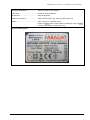
APPLICATION FOR LOW VOLTAGE DIRECTIVE
On Behalf Of
Company Limited Liability « Faraday Electronics »
Switching Mode Power Adaptor
Model: 19W/14.4V/EU(18V/1.0A), 19W/14.4V/EU(12V/1.5A)
Prepared For
:
Company Limited Liability « Faraday Electronics »
Flat 37, House 4, UL Kirovogradskaya, Kiev,
Ukraine
Tel: +38-67-238-39-44
Prepared By
:
Shenzhen PTSI Testing Co., Ltd.
7/F, Baoyuan Building, Baoyuan Road, Xixiang,
Baoan, Shenzhen, Guangdong, China
Tel : +86-755-27820019
Fax: +86-755-27215519
Report Number
Date of Test
Date of Report
:
:
:
PSZ1204026S
April 05, 2012 – April 11, 2012
April 12, 2012
SHENZHEN PTSI TESTING CO., LTD. REPORT NO. PSZ1204026S
Test item description..................... :
Switching Mode Power Adaptor
Trade Mark .......................................:
FARADAY ELECTRONICS
Manufacturer ....................................:
Same as applicant
Model/Type reference.......................:
19W/14.4V/EU(18V/1.0A), 19W/14.4V/EU(12V/1.5A)
Ratings .............................................:
Input: 100-240 V~, 50/60Hz, 0.45A
Output: 18V
, 1.0A for model 19W/14.4V/EU(18V/1.0A); 12V
,
1.5A for model 19W/14.4V/EU(12V/1.5A)
Copy of marking plate
Page 2 of 36
SHENZHEN PTSI TESTING CO., LTD. REPORT NO. PSZ1204026S
Summary of testing:
1)
The Maximum ambient temperature: 35°C.
2)
Following tests performed during evaluation.
Clause(s)
Test(s)
5
Durability of Marking Test
5.1
Input Current Test
7.1
Heating under Normal Operations
7.2
Softening Test for insulation material
9.1.1.1
Touch current
9.1.6
Discharge Test of Mains Plug
9.1.7
Resistance to external Forces (50N)
10.1
Surge Test
10.2
Humidity Test
10.3
Insulation Resistance and Electric Strength
11.1
Touch current under Fault Conditions
11.2
Heating under Fault Conditions
12.1.2
Vibration test
12.1.3
Impact Test
12.1.4
Drop Test
12.1.5
Stress Relieve Test
13.2
Working Voltages
15.4.1
Torque on the socket-outlet test
Page 3 of 36
SHENZHEN PTSI TESTING CO., LTD. REPORT NO. PSZ1204026S
Test item particulars...................................................: Movable equipment
Classification of installation and use ............................: Class II
Supply connection .......................................................: ±10%
Possible test case verdicts:
- test case does not apply to the test object .................: N/A
- test object does meet the requirement .......................: Pass (P)
- test object does not meet the requirement .................: Fail (F)
Testing:
Date of receipt of test items.......................................... : April 05, 2012
Date(s) of performance of tests.....................................: April 05, 2012 to April 11, 2012
General remarks:
The test results presented in this report relate only to the object tested.
This report shall not be reproduced, except in full, without the written approval of the Issuing testing laboratory.
"(see Enclosure #)" refers to additional information appended to the report.
"(see appended table)" refers to a table appended to the report.
Throughout this report, a point (coma) is used as the decimal separator.
List of test equipment must be kept on file and available for review.
General product information:
The EUT covered by this report is a desk-top switching mode power adaptor with model:
19W/14.4V/EU(18V/1.0A) & 19W/14.4V/EU (12V/ 1.5A), used with audio, video and similar electronics
apparatus. The two models are identical, only except the output rating, see below for details:
Input: 100-240 V~, 50/60Hz, 0.45A
Output: 18V
1.5A).
, 1.0A for model 19W/14.4V/EU(18V/1.0A); 12V
, 1.5A for model 19W/14.4V/EU (12V/
Model 19W/14.4V/EU (12V/ 1.5A) has larger output current, selected as the Representative model.
The switching power supply’s bottom enclosure is secured to top enclosure by ultrasonic-wave welding.
Page 4 of 36
SHENZHEN PTSI TESTING CO., LTD. REPORT NO. PSZ1204026S
EN 60065
Clause
Requirement – Test
3
General requirements
Safety class of the apparatus .................................:
4
General test conditions
4.1.4
Ventilation instructions require the use of the test box
5
Marking and instructions
5.1
Result - Remark
Verdict
P
Class II equipment
P
P
Not used
N/A
P
Comprehensible and easily discernible
The rating label is easily
discernible.
P
Permanent durability against water and petroleum
spirit
Compliance was checked
by rubbing the marking by
hand for 15 s with cloth
soaked with water and cloth
soaked with petroleum
spirit, it was not possible to
remove marking plate and
no curling observed after
the test.
P
a) Identification, maker ………………………………..:
(see copy of marking plate
on page 2)
P
b) Model number or type reference …………………..:
(see copy of marking plate
on page 2)
P
c) Class II symbol if applicable ………………………..:
Class II symbol on the
rating label
P
d) Nature of supply ………………………………….....:
(see copy of marking plate
on page 2)
P
e) Rated supply voltage and symbol …………………:
(see copy of marking plate
on page 2)
P
f) Mains frequency if safety dependant ……......…….:
(see copy of marking plate
on page 2)
P
g) Rated current or power consumption for apparatus
supplied by supply apparatus for general use ………:
(see copy of marking plate
on page 2, see also
appended table 7.1)
P
Measured current or power consumption …………...:
P
Deviation % (max 10%) ……………………………....:
P
h) Power consumption marking for apparatus other
than single phase ……………………………..……….:
P
i) Rated current or power consumption for apparatus
intended for connection to an a.c. mains supply ……:
P
Measured current or power consumption …..…….....:
P
Deviation % (max 10%) ……………………………....:
P
Page 5 of 36
SHENZHEN PTSI TESTING CO., LTD. REPORT NO. PSZ1204026S
EN 60065
Clause
Requirement – Test
Result - Remark
Verdict
5.2
Earth terminal
Class II equipment
N/A
Hazardous live terminals
No such terminals
N/A
Supply output terminals (other than mains)
No such terminals
N/A
5.3
Use of triangle with exclamation mark
Marked in circuit diagram
P
5.4
Instructions for use
English and German
P
(Version in other language
will be provided when
submitted for national
approval)
5.4.1
a) Mains powered equipment not exposed to dripping
or splashing. Warning concerning objects filled with
liquid, etc. ……………………………………………….:
Mentioned in user manual
b) Hazardous live terminals, instructions for wiring ...:
No such terminals
N/A
c) Instructions for replacing lithium battery …………..:
No lithium battery used
N/A
d) Class I earth connection warning ………………….:
Class II equipment
N/A
e) Instructions for multimedia system connection …..:
No such system
N/A
f) Special stability warning for attachment of the
apparatus to the flor/wall ………………………………:
Not this type apparatus
N/A
g) Warning: battery exposure to heat ………………..:
5.4.2
N/A
h) Warning: protective film on CRT face …………….:
No such devices
Disconnect device: plug/coupler or all-pole mains
switch location, accessibility and markings
Power plug provided
P
Instructions for permanently connected equipment
No such equipment
N/A
Marking, signal lamps or similar for completely
disconnection from the mains ……………………...…:
6
Hazardous radiation
6.1
Ionizing radiation < 36 pA/kg (0,5 mR/h) …………….:
Laser radiation, emission limits to IEC 60825-1 …….:
N/A
N/A
P
No ionizing radiation
Ionizing radiation under fault condition ……………….:
6.2
P
N/A
N/A
No laser radiation
Emission limits under fault conditions ………………..:
N/A
N/A
7
Heating under normal operating conditions
7.1
Temperature rises not exceeding specified values, no
operation of fuse links
(see appended table 7.1)
P
7.1.1
Temperature rise of accessible parts
(see appended table 7.1)
P
7.1.2
Temperature rise of parts providing electrical
insulation
(see appended table 7.1)
P
P
Page 6 of 36
SHENZHEN PTSI TESTING CO., LTD. REPORT NO. PSZ1204026S
EN 60065
Clause
Requirement – Test
Result - Remark
7.1.3
Temperature rise of parts acting as a support or as a
mechanical barrier
(see appended table 7.1)
P
7.1.4
Temperature rise of windings
(see appended table 7.1)
P
7.1.5
Parts not subject to a limit under 7.1.1 to 7.1.4
7.2
Softening temperature of insulating material
supporting parts conductively connected to the mains
carrying a current > 0,2 A at least 150 oC
8
Constructional requirements with regard to the protection against electric
shock
P
8.1
Conductive parts covered by lacquer, paper, untreated Not used
textile oxide films and beads etc. considered to be
bare
P
8.2
No shock hazard when changing voltage setting
device, fuse-links or handling drawers etc.
No voltage setting device. It
is not possible for user to
access fuse-links. No
indicators and drawers
used.
N/A
8.3
Insulation of hazardous live parts not provided by
hygroscopic material
Not used
N/A
8.4
No risk of electric shock from accessible parts or from No such a cover which can
parts rendered accessible following the removal of a
be removed by hand.
cover which can be removed by hand …………..:
8.5
Class I equipment
8.6
Verdict
N/A
Bobbin (Phenolic) of T1 and
L1 are considered to be
sufficient in regard to the
temperature characteristic
(150 °C). No other parts to
be tested.
Class II equipment
P
N/A
N/A
Basic insulation between hazardous live parts and
earthed accessible parts
N/A
Resistors bridging basic insulation complying with
14.1 a)
N/A
Capacitors bridging basic insulation complying with
14.2.1 a) …………………………………………….......:
N/A
Protective earthing terminal …………………………...:
N/A
Class II equipment and Class II constructions within
Class I equipment
Class II equipment
P
Reinforced or double insulation between hazardous
live parts and accessible parts
Reinforced or double
insulation used between
hazardous live parts and
accessible parts
P
Page 7 of 36
SHENZHEN PTSI TESTING CO., LTD. REPORT NO. PSZ1204026S
EN 60065
Clause
Requirement – Test
Result - Remark
Components bridging reinforced or double insulation
complying with 14.1 a) or 14.3
Switching isolating
transformer complying with
14.3
Basic insulation bridged by components complying
with 14.3.4.3. …………………………………………...:
No such components
N/A
Basic and supplementary insulation each being
bridged by a capacitor complying with 14.2.1 a) ……:
No such capacitors
N/A
Double or reinforced insulation being bridged with 2
capacitors in series complying with 14.2.1 a) ……….:
No such capacitors
N/A
Double or reinforced insulation being bridged with a
single capacitor complying with 14.2.1 b) ……………:
Approved Y1 capacitor
(CY1) bridged between
primary and secondary
8.7
This clause is void
8.8
Basic or supplementary insulation > 0,4 mm (mm) :
Reinforced insulation > 0,4 mm (mm) ....................:
Verdict
P
P
-N/A
Thickness of enclosure:
2.0mm, for optocoupler see
clause 14.11.
P
Thin sheet insulation (excluding non-separable thin
sheet insulation. See 8.22)
N/A
Basic or supplementary insulation, at least two layers,
each meeting 10.3
N/A
Basic or supplementary insulation, three layers any
two of which meet 10.3
N/A
Reinforced insulation, two layers each of which meet
10.3
2 layers insulation tape
wrapped around external of
transformer T1.
P
2 layers insulation tape
wrapped on primary and
secondary heat sink.
One of two layers passes
dielectric strength test
specified in 10.3 for
reinforced insulation.
Reinforced insulation, three layers any two which
meet 10.3
8.9
8.10
N/A
Adequate insulation between internal hazardous live
conductors and accessible parts
Double/reinforced insulation
between primary live parts
and accessible parts.
P
Adequate insulation between internal hazardous live
parts and conductors connected to accessible parts
No secondary wires can
touch primary parts.
P
Double insulation between conductors connected to
the mains and accessible parts.
Double insulation between internal hazardous live
parts and conductors connected to accessible parts.
See clause 8.9
P
Page 8 of 36
SHENZHEN PTSI TESTING CO., LTD. REPORT NO. PSZ1204026S
EN 60065
Clause
Requirement – Test
8.11
Detaching of wires
No undue reduction of creepages or clearance
distances if wires become detached
Result - Remark
Verdict
P
Secondary internal wires
connected to PCB by
soldering and fixed by glue.
P
Vibration test carried out .........................................:
P
8.12
This clause is void
--
8.13
Adequate fastening of windows, lenses, lamp covers
etc. (pull test 20 N for 10 s)
No such devices
8.14
Adequate fastening of covers (push/pull test 50 N for
10 s)
Enclosure only
P
8.15
No risk of damage to the insulation of internal wiring
due to hot parts or sharp edges
Internal wires can’t touch
hot parts or sharp edges
which can damage its
insulation
P
8.16
Only special supply equipment can be used
8.17
Insulated winding wire without additional interleaved
insulation
8.18
Endurance test as required by 8.17
8.19
Disconnection from the mains
8.19.1
Disconnect device
Appliance inlet used for
disconnect device
All-pole switch or circuit breaker with > 3 mm contact
separation
See above
N/A
8.19.2
Mains switch ON indication
No mains switch used
N/A
8.20
Switch not fitted in the mains cord
8.21
Bridging components comply with clause 14
No mains switch used
N/A
8.22
Non-separable thin sheet material
No such material
N/A
9
Electric shock hazard under normal operating conditions
P
9.1
Testing on the outside
P
9.1.1
For voltages >1000 V ac or >1500 V dc complies
with clause 13.3.1 for basic insulation
No such high voltage
9.1.1.1
a) Open circuit voltages
Measured max. open circuit
voltage for output terminal
not exceeding 60Vd.c.
P
b) Touch current measured from terminal devices
using the network in annex D .................................:
(see appended table
9.1.1.1)
P
N/A
N/A
VDE approved triple
insulated wire used in T1,
see appendix 1 for
transformer construction.
P
N/A
P
P
P
N/A
Page 9 of 36
SHENZHEN PTSI TESTING CO., LTD. REPORT NO. PSZ1204026S
EN 60065
Clause
Requirement – Test
Result - Remark
Verdict
c) Discharge not exceeding 45 µC
Discharge not exceeding
45 µC
N/A
d) Energy of discharge not exceeding 350 mJ
Open circuit voltage <15 KV
N/A
9.1.1.2
Test with test finger and test probe
9.1.2
No hazardous live shafts of knobs, handles or levers
No hazards, compliance
was checked according to
clause 9.1.1.
9.1.3
Ventilation holes and other holes tested by means of
4 mm x 100 mm test pin
No ventilation openings
N/A
9.1.4
Terminal devices tested with 1 mm x 20 mm test pin
(10 N); test probe D of IEC 61032
No such terminal devices
N/A
P
P
Terminal devices tested with 1 mm x 100 mm straight
wire (1 N); test probe D of IEC 61032
N/A
9.1.5
Pre-set controls tested with 2.5 mm x 100 mm test pin No pre-set controls used
(10 N); test probe C of IEC 61032
N/A
9.1.6
No shock hazard due to stored charge on withdrawal
of the mains plug; voltage (V) after 2 s ...................:
4V measured
P
If C is not greater than 0,1 uF no test needed
CX1=0.22uF
P
9.1.7
Enclosure sufficiently resistant to external force
P
a)Test probe 11 of IEC 61032 for 10 s (50 N)
P
b) Test hook of fig. 4 for 10 s (20 N)
P
c) 30 mm diameter test tool for 5 s (100 or 250 N) :
Plastic enclosure used.
N/A
9.2
No hazard after removing a cover by hand
No cover can be removed
by hand
N/A
10
Insulation requirements
10.1
Insulation resistance (MΩ) at least 2 MΩ min. after
surge test for basic and 4 MΩ min. for reinforced
insulation .................................................................:
Tested between primary
and accessible parts, after
tested, EUT complied with
the requirements of 10.3
P
10.2
Humidity treatment 48 h or 120 h ...........................:
93% R.H., 30ºC, 48h
P
10.3
Insulation resistance and dielectric strength between
mains terminals
(see appended table 10.3)
P
Insulation Resistance and dielectric strength across
BASIC or SUPPLEMENTARY insulation (Class 1)
Class II equipment
11
P
N/A
Insulation resistance and dielectric strength across
REINFORCED insulation (Class II)
P
Fault conditions
P
Page 10 of 36
SHENZHEN PTSI TESTING CO., LTD. REPORT NO. PSZ1204026S
EN 60065
Clause
Requirement – Test
Result - Remark
11.1
No shock hazard under fault condition
(see appended table 11.1)
11.2
Heating under fault condition
Verdict
P
P
No hazard from softening solder
No solder soften during the
test.
Flames extinguish within 10 seconds
No flames occurred
Soldered terminations not used as protective
mechanism
P
N/A
P
11.2.1
Measurement of temperature rises
(see appended table 11.2)
P
11.2.2
Temperature rise of accessible parts
(see appended table 11.2 )
P
11.2.3
Temperature rise of parts, other than windings,
providing electrical insulation
Temperature rise of printed circuit boards (PCB)
exceeding the limits of table 3 by max. 100 K for max.
5 min
P
None exceeding limits
N/A
a) Temperature rise of printed circuit boards (PCB) to
20.1.3, exceeding the limits of table 3 by not more
than 100 K for an area not greater than 2 cm²
N/A
b) Temperature rise of printed circuit boards (PCB) to
20.1.3 up to 300 K for an area not greater than 2 cm²
for a maximum of 5 min
N/A
Meets all the special conditions if conductors on
printed circuit boards are interrupted
N/A
Class I protective earthing maintained
Class II equipment
11.2.4
Temperature rise of parts acting as a support or
mechanical barrier
(see appended table 11.2)
P
11.2.5
Temperature rise of windings
(see appended table 11.2)
P
11.2.6
Temperature rise of parts not subject to the limits of
11.2.1 to 11.2.5
12
Mechanical strength
12.1.1
Bump test where mass >7 kg
12.1.2
Vibration test
12.1.3
Impact hammer test
N/A
N/A
P
Measured mass: 80g
N/A
P
0.5J, 3 times
P
(After test, no damage and
EUT can withstand the
dielectric strength test as
specified in 10.3 )
Page 11 of 36
SHENZHEN PTSI TESTING CO., LTD. REPORT NO. PSZ1204026S
EN 60065
Clause
Requirement – Test
Result - Remark
Steel ball test
2J, 1 time
Verdict
P
(After test, no damage and
EUT can withstand the
dielectric strength test as
specified in 10.3 )
12.1.4
Drop test for portable apparatus where mass < 7 kg
3 times, 1000mm
P
(After test, no damage and
EUT can withstand the
dielectric strength test as
specified in 10.3 )
12.1.5
Thermoplastic enclosures stress relief test
Test conditions: 104°C, 7h
for enclosure
P
(After test , no shrinkage or
distortion for enclosure)
12.2
Fixing of knobs, push buttons, keys and levers
No such elements
N/A
12.3
Remote controls with hazardous live parts
No remote controls
N/A
12.4
Drawers (pull test 50 N, 10 s)
No drawers
N/A
12.5
Antenna coaxial sockets providing isolation
No antenna coaxial
sockets
N/A
12.6
Telescoping or rod antennas construction
No such devices
N/A
12.6.1
Telescoping or rod antennas securement
No such devices
N/A
13
Clearances and creepage distances
13.1
Clearances in accordance with 13.3
(see appended table 13.3 &
13.4)
P
Creepage distances in accordance with 13.4
(see appended table 13.3 &
13.4)
P
13.2
Determination of operating voltage
(see appended table 13.2)
P
13.3
Clearances
(see appended table 13.3 &
13.4)
P
13.3.1
General
P
13.3.2
Circuits conductively connected to the mains comply
with table 8 and, where applicable, table 9
P
13.3.3
Circuits not conductively connected to the mains
comply with table 10
13.3.4
Measurement of transient voltages
13.4
Creepage distances
Creepage distances greater than table 11 minimum
values
P
No hazard when short
circuited according to
clause 11.
P
N/A
(see appended table 13.3 &
13.4)
P
P
Page 12 of 36
SHENZHEN PTSI TESTING CO., LTD. REPORT NO. PSZ1204026S
EN 60065
Clause
Requirement – Test
Result - Remark
13.5
Printed boards
No such printed boards
13.5.1
Clearances and creepage distances between
conductors on printed circuit boards, one of which
may be conductively connected to the mains, as in
fig. 10
N/A
13.5.2
Type B coated printed circuit boards complying with
IEC 60664-3 (basic insulation only)
N/A
13.6
Conductive parts along uncemented joints clearances No such parts
and creepage distances comply with 13.3 and 13.4
N/A
Conductive parts along reliably cemented joints
comply with 8.8
N/A
Temperature cycle test and dielectric strength test
N/A
13.7
Enclosed, enveloped or hermetically sealed parts: not
conductively connected to the mains: clearances and
creepage distances as in table 12
N/A
13.8
Parts filled with insulating compound, meeting the
requirements of 8.8
14
Components
P
14.1
Resistors
P
a) Resistors between hazardous live parts and
accessible metal parts
14.2
Approved opto-coupler with
insulation thickness min.
0.4mm.
No such resistors
Verdict
N/A
P
N/A
b) Resistors, other than between hazardous live parts
and accessible parts
N/A
Resistors separately approved ...............................:
N/A
Capacitors and RC units
P
Capacitors separately approved
See below
P
14.2.1
Y capacitors tested to IEC 60384-14, 2 edition ...:
Approved Y1-Cap (CY1)
used
P
14.2.2
X capacitors tested to IEC 60384-14, 2nd edition ...:
Approved X2-cap (CX1)
used
P
14.2.3
Capacitors operating at mains frequency but not
connected to the mains: tests for X2 ......................:
No such capacitors
N/A
14.2.5
Capacitors with volume exceeding 1750 mm³, where
short-circuit current exceeds 0,2 A: compliance with
IEC60384-1, 4.38 category B or better ...................:
See below
N/A
nd
Capacitors with volume exceeding 1750 mm³,
mounted closer to a potential ignition source than
table 5 permits: compliance with IEC 60 384-1, 4.38
category B or better .................................................:
N/A
Page 13 of 36
SHENZHEN PTSI TESTING CO., LTD. REPORT NO. PSZ1204026S
EN 60065
Clause
14.3
14.3.1
14.3.2
Requirement – Test
Result - Remark
Shielded by a barrier acc. To 20.1.4/ table 21 or metal
..................................................................................:
Metal-cased capacitors
used
Inductors and windings
Verdict
P
P
Comply with IEC 61558-1, IEC 61558-2
(as relevant) and clause 20.1.4
Tested with appliance
Transformers and inductors marked with
manufacturer’s name and type ...............................:
See table 14 for details
Transformers and inductors separately approved .:
Tested with appliance
N/A
P
N/A
General
P
Insulation material complies with clause 20.1.4
P
14.3.3
Constructional requirements
Class II construction
P
14.3.3.1
Clearances and creepage distances comply with
clause 13
Clearance and creepage
distance comply with the
requirements of clause 13.
P
14.3.3.2
Transformers meet the constructional requirements
P
14.3.4
Separation between windings
P
14.3.4.1
Class II transformers have adequate separation
between hazardous live parts and accessible parts
(double or reinforced insulation)
Double or reinforced
insulation used between
hazardous live parts and
accessible parts
P
Coil formers and partition walls > 0,4 mm
0.8mm
P
14.3.4.2
Class I transformers, with basic insulation and
protective screening only if all 7 conditions of 14.3.4.2
are met
Class II transformer
14.3.4.3
Separating transformers with at least basic insulation
14.3.5
Insulation between HAZARDOUS LIVE parts and
ACCESSIBLE parts
14.3.5.1
Class II transformers have adequate insulation
between hazardous live parts and accessible parts
(double or reinforced insulation)
(see clause 14.3.4.1)
P
Coil formers and partition walls > 0,4 mm
0.8mm
P
Class I transformers have adequate insulation
between hazardous live parts and accessible
conductive parts or those conductive parts or
protective screens connected to a protective earth
terminal
Class II transformer
14.3.5.2
N/A
P
Winding wires connected to protective earth have
adequate current-carrying capacity
14.4
High voltage components
N/A
N/A
N/A
No such components
N/A
Page 14 of 36
SHENZHEN PTSI TESTING CO., LTD. REPORT NO. PSZ1204026S
EN 60065
Clause
Requirement – Test
Result - Remark
Verdict
High-voltage components and assemblies: U > 4 Kv
(peak) separately approved
N/A
Component meets category V-1 of IEC 60707
N/A
14.4.1
High voltage transformers and multipliers tested as
part of the submission
N/A
14.4.2
High voltage assemblies and other parts tested as
part of the submission
N/A
14.5
Protective devices
P
Protective devices used within their ratings
P
14.5.1.1
External clearances and creepage distances meet
requirement of clause 13 for the voltage across the
device when opened
(see appended table 13.1)
P
a) Thermal cut-outs separately approved
No thermal cut-outs used
N/A
b) Thermal cut-outs tested as part of the submission
14.5.1.2
a) Thermal links separately approved
N/A
No thermal links used
b) Thermal links tested as part of the submission
N/A
N/A
14.5.1.3
Thermal devices re-settable by soldering
No such devices
14.5.2.1
Fuse-links in the mains circuit according to IEC 60127 Approved fuse according to
IEC 60127 standard used,
also see table 14
14.5.2.2
Correct marking of fuse-links adjacent to holder ....:
Approved fuse rating
marked close to fuse on
PCB.
14.5.2.3
Not possible to connect fuses in parallel ................:
No fuse holder used
N/A
14.5.2.4
Not possible to touch hazardous live parts when
replacing fuse-links without the use of a tool .........:
Fuse is not accessible by
operator
N/A
14.5.3
PTC-S thermistors comply with IEC 60730-1
No such components
N/A
N/A
P
P
PTC-S devices (15 W) category V-1 or better
N/A
14.5.4
Circuit protectors have adequate breaking capacity
and their position is correctly marked
N/A
14.6
Switches
14.6.1 a)
Separate testing to IEC 61058 including:
No switches used.
N/A
P
- 10 000 operations
- Normal pollution suitability
- Resistance to heat and fire level 3
- Make and break speed independent of speed of
actuation
V-0 compliance with annex G, G.1.1 ………………...:
14.6.1 b)
Tested in the apparatus:
N/A
Page 15 of 36
SHENZHEN PTSI TESTING CO., LTD. REPORT NO. PSZ1204026S
EN 60065
Clause
Requirement – Test
Result - Remark
Verdict
Switch controlling > 0.2A with open contact voltage >
35 V (peak)/24 V dc complying with 14.6.3, 14.6.4 and
V-0 in annex G, G.1.1
N/A
Switch controlling > 0.2A with open contact voltage <
35 V (peak)/24 V dc complying with 14.6.3 and V-0 in
annex G, G.1.1
N/A
Switch controlling < 0.2A with open contact voltage >
35 V (peak)/24 V dc complying with 14.6.4 and V-0 in
annex G, G.1.1
N/A
14.6.2
Switch tested to 14.6.1 b) constructed to IEC 61058-1
subclause 13.1 and has making/breaking action
independent of speed of actuation
N/A
14.6.3
Switch tested to 14.6.1 b) compliant with IEC 61058-1
subclause 16.2.2 d) and m) not attaining excessive
temperatures in use
N/A
14.6.4
Switch tested to 14.6.1 b) has adequate dielectric
strength
N/A
14.6.5
Mains switch controlling mains socket outlets
additional tests to IEC 60058-1
N/A
Socket outlet current marking correct
N/A
14.7
14.8
Safety interlocks
No safety interlocks used
N/A
Safety interlocks to 2.8 of IEC 60950
N/A
Voltage setting devices and the like
N/A
Voltage setting device not likely to be changed
accidentally
N/A
14.9
Motors
No motors used
14.9.1
Endurance test on motors
N/A
Motor start test
N/A
Dielectric strength test
N/A
14.9.2
Not adversely affected by oil or grease etc.
N/A
14.9.3
Protection against moving parts
N/A
14.9.4
Motors with phase-shifting capacitors, three-phase
motors and series motors meet clause. B.8, B.9 and
B.10 of IEC 60950, Annex B
N/A
14.10
Batteries
14.10.1
Batteries mounted with no risk of accumulation of
flammable gases
N/A
14.10.2
No possibility of recharging non-rechargeable
batteries
N/A
No batteries used
N/A
N/A
Page 16 of 36
SHENZHEN PTSI TESTING CO., LTD. REPORT NO. PSZ1204026S
EN 60065
Clause
Requirement – Test
14.10.3
Recharging currents and times within manufacturers
limits
N/A
Lithium batteries discharge and reverse currents
within the manufacturers limits
N/A
14.10.4
Battery mould stress relief
N/A
14.10.5
Battery drop test
N/A
14.11
Optocouplers
Approved optocoupler(U2)
used
P
Optocouplers comply with Cl. 8
Verified dti ≥ 0.4mm
P
Internal and external dimensions to 13.1. or
alternatively 13.6 (jointed insulation)
See appended table 13.3 &
13.4
P
Surge suppression varistors
No such component used
14.12
Result - Remark
N/A
Comply with IEC 61051-2
N/A
Not connected between mains and accessible parts
except for earthed parts of permanently connected
apparatus
N/A
Complies with the current pulse, fire hazard and
thermal stress requirements of 14.12
N/A
15
Terminals
15.1.1
Mains plug, appliance inlet, interconnection couplers
and mains socket-outlet meet the appropriate
standard
Mains plug meets the
appropriate standard
Overloading of plugs or appliance inlets prevented if
the apparatus has mains socket outlets
No mains socket outlets
used
15.1.2
Verdict
P
P
N/A
Overloading of internal wiring prevented if the
apparatus has mains socket outlets
N/A
Connectors for antenna, earth, audio, video or data:
N/A
No risk of insertion in mains socket-outlets
N/A
No risk of insertion into audio or video: outlets marked No such outlets
with the symbol of 5.2
N/A
15.1.3
Output terminals of a.c. adaptors or similar devices
not compatible with household mains socket-outlets
15.2
Provision for protective earthing
Accessible conductive parts of Class I equipment
reliably connected to earth terminal, within equipment
Protective earth conductors correctly coloured
Output plug not compatible
with sockets according to
IEC 60083 or IEC 60320
P
N/A
Class II equipment
N/A
N/A
Page 17 of 36
SHENZHEN PTSI TESTING CO., LTD. REPORT NO. PSZ1204026S
EN 60065
Clause
Requirement – Test
Result - Remark
Verdict
Equipment with non-detachable mains cord provided
with separate protective earth terminal near mains
input
N/A
Protective earth terminal resistant to corrosion
N/A
Earth resistance test: < 0,1 Ω at 25 A ....................:
N/A
15.3
Terminals for external flexible cords and for
permanent connection to the mains supply
15.3.1
Adequate terminals for connection of permanent
wiring
N/A
15.3.2
Reliable connection of non-detachable cords:
N/A
Not soldered to conductors of a printed circuit board
N/A
Adequate clearances and creepage distances
between connections should a wire break away
N/A
Wire secured by additional means to the conductor
N/A
15.3.3
Screws and nuts clamping conductors have adequate No such screws and nuts
threads: ISO 261, ISO 262 or similar
N/A
15.3.4
Soldered conductors wrapped around terminal prior to
soldering or held in place by additional means
N/A
Clamping of conductor and insulation if not soldered
or held by screws
N/A
15.3.5
Terminals allow connection of appropriate crosssectional area of conductors, for the rated current of
the equipment
N/A
15.3.6
Terminals to 15.3.3 have sizes required by table 16
N/A
15.3.7
Terminals clamp conductors between metal and have
adequate pressure
N/A
Terminals designed to avoid conductor slipping out
when tightened or loosened
N/A
Terminals adequately fixed to avoid loosening when
the clamping is tightened or loosened and stress on
internal wiring is avoided
N/A
15.3.8
Terminals carrying a current more than 0,2 A: contact
pressure not transmitted by insulating material except
ceramic
N/A
15.3.9
Termination of non-detachable cords: wires terminated
near to each other
N/A
Terminals located and shielded: test with 8 mm strand
N/A
15.4
Devices forming a part of the mains plug
15.4.1
No undue strain on mains socket-outlets
No such terminals
Not Direct plug-in
N/A
N/A
N/A
Page 18 of 36
SHENZHEN PTSI TESTING CO., LTD. REPORT NO. PSZ1204026S
EN 60065
Clause
Requirement – Test
Result - Remark
15.4.2
Device complies with standard for dimensions of
mains plugs
N/A
15.4.3
Device has adequate mechanical strength (tests
a,b,c)
N/A
16
External flexible cords
P
16.1
Mains cords sheathed type, complying with IEC 60227
for PVC or IEC 60245 for synthetic rubber cords ...:
P
Non-detachable cords for Class I have green/yellow
core for protective earth
Verdict
N/A
0.75mm2x2
16.2
Mains cords conductors have adequate crosssectional area for rated current consumption of the
equipment
16.3
No such flexible cords
a) Flexible cords not complying with 16.1, used for
interconnections between separate units of equipment
used in combination and carrying hazardous live
voltages, have adequate dielectric strength
N/A
b) Flexible cords not complying with 16.1, withstand
bending and mechanical stress (3.2 of IEC 60227-2)
N/A
P
16.4
Flexible cords used for connection between
equipment have adequate cross-sectional areas to
avoid temperature rise under normal and fault
conditions
Cross-sectional areas of
output cord suitable for the
intended current
P
16.5
Adequate strain relief on external flexible cords
Cord anchorage used on
external flexible cord. It
provided adequate strain
relief. Displacement:
0,6mm.
P
Not possible to push cord back into equipment
P
Strain relief device unlikely to damage flexible cord
P
For mains cords of Class I equipment, hazardous live
conductors become taut before earth conductor
16.6
Apertures for external flexible cord: no risk of damage
to the cord during assembly or movement in use
16.7
Transportable musical instruments and amplifiers
fitted with detachable cord set with appliance inlet to
IEC 60320-1
Transportable musical instruments and amplifiers
fitted with detachable cord sets or with means of
stowage to protect the cord
Class II equipment
N/A
N/A
No transportable musical
instrument
N/A
N/A
Page 19 of 36
SHENZHEN PTSI TESTING CO., LTD. REPORT NO. PSZ1204026S
EN 60065
Clause
Requirement – Test
17
Electrical connections and mechanical fixings
17.1
Torque test to table 20:
Result - Remark
Verdict
P
No fixing screws used.
N/A
- screws into metal: 5 times
N/A
- screws into non-metallic material: 10 times
N/A
17.2
Correct introduction into female threads in nonmetallic material
N/A
17.3
Cover fixing screws: captive
N/A
Non-captive fixing screws: no hazard when replaced
by a screw whose length is 10 times its diameter
N/A
17.4
No loosening of conductive parts carrying a current
> 0,2 A
N/A
17.5
Contact pressure not transmitted through plastic other
than ceramic for connections carrying a current
> 0,2 A
P
17.6
Stranded conductors of flexible supply cords carrying
a current > 0,2 A with screw terminals not
consolidated by solder
N/A
17.7
Cover fixing devices other than screws have adequate
strength and their positioning is unambiguous
N/A
17.8
Fixing devices for detachable legs or stands provided
N/A
17.9
Internal pluggable connections, affecting safety,
unlikely to become disconnected
18
Mechanical strength of picture tubes and protection against the effects of
implosion
N/A
Picture tube separately approved to IEC 61965:
N/A
No such connections
No picture tube used
N/A
Picture tube separately approved to 18.1 ................
N/A
Picture tubes > 16 cm intrinsically protected
N/A
Non-intrinsically protected tubes > 16 cm used with
protective screen
N/A
Protective film as part of implosion protection: edges
covered by enclosure
N/A
18.2
Intrinsically protected tubes: tests on 12 samples
N/A
18.2.1
Samples subject to ageing: 6
N/A
18.2.2
Samples subject to implosion test: 6
N/A
18.2.3
Samples subject to mechanical strength test (steel
ball): 6
N/A
18.3
Non-intrinsically protected tubes tested to 18.3
N/A
18.1
Page 20 of 36
SHENZHEN PTSI TESTING CO., LTD. REPORT NO. PSZ1204026S
EN 60065
Clause
Requirement – Test
19
Stability and mechanical hazards
Result - Remark
Verdict
P
Mass of the equipment exceeding 7 kg ..................:
No glass surface
N/A
Apparatus intended to be fastened in place – suitable
instructions
Not this type apparatus
N/A
19.1
Test on a plane, inclined at 10o to the horizontal
N/A
19.2
100 N force applied vertically downwards
N/A
19.3
100 N force, or 13% of weight, applied horizontally to
point of least stability.
N/A
19.4
Edges or corners not hazardous
Edges and corners are
smoothed
19.5
Glass surfaces (exc. Laminated) with an area
exceeding 0,1 m² or maximum dimension > 450 mm,
pass the test of 19.5.1
No glass surface
19.6
Wall or ceiling mountings adequate
20
Resistance to fire
P
20.1
Electrical components and mechanical parts
P
a) Exemption for components contained in an
enclosure of material V-0 to IEC 60695-11-10 with
openings not exceeding 1 mm in width
P
N/A
N/A
Plastic enclosure with a
flammability category of V0 used. Openings less than
1mm width or completely
filled by wiring.
P
b) Exemption for small components as defined in 20.1 Some small components
mounted on UL approved
PCB with flammability of V0.
P
20.1.1
Electrical components meet the requirements of
Clause 14 or 20.1.4
P
20.1.2
Insulation of internal wiring working at voltages > 4 Kv
or leaving an internal fire enclosure, or located within
the areas mentioned in Table 21, not contributing to
the spread of fire
20.1.3
V-0 PCB used.
Material of printed circuit boards on which the
available power exceeds 15 W at a voltage between
50 V and 400 V (peak) a.c. or d.c. meets V-1 or better
to IEC60707, unless used in a fire enclosure
Material of printed circuit boards on which the
available power exceeds 15 W at a voltage > 400 V
(peak) a.c. or d.c. meets V-0 to IEC 60707
a) wiring working at voltage
< 4 kV (peak) a.c or d.c; b)
no internal fire enclosure;
c) no such wiring
See above.
N/A
P
P
Page 21 of 36
SHENZHEN PTSI TESTING CO., LTD. REPORT NO. PSZ1204026S
EN 60065
Clause
Requirement – Test
Result - Remark
20.1.4
Components and parts not covered by 20.1.1, 20.1.2 See clause 20.1
and 20.1.3 (other than fire enclosures) mounted
nearer to a potential ignition source than the distances
in Table 21 comply with the relevant flammability
category in Table 21
N/A
Components and parts as above but shielded from a
potential ignition source, with the barrier area in
accordance with Table 21 and fig. 13
N/A
Apparatus with voltages > 4Kv under normal operating
conditions and distances to the enclosure exceed
those specified Table 21, flammability classification
HB40 or better is required for the enclosure.
N/A
20.2
Fire enclosure
N/A
20.2.1
Potential ignition sources with open circuit voltage
> 4 Kv (peak) a.c. or d.c. contained in a fire enclosure
to V-1
Open circuit voltage not
exceeding 4 kV (peak) a.c.
or d.c.
N/A
20.2.2
Internal fire enclosures with openings not exceeding
1 mm in width and with openings for wires completely
filled
No internal fire enclosure.
N/A
20.2.3
Requirements of 20.2.1 and 20.2.2 met by an internal
fire enclosure
N/A
A
Annex A, Additional requirements for apparatus with protection against
splashing water
N/A
A.5
Marking and instructions
N/A
A.5.1
j) Marked with IPX4 (IEC 60529), 5.4.1 a) does not
apply
A.10.2
Insulation requirements
A.10.2.1
Enclosure provides protection against splashing water
N/A
A.10.2.2
Humidity treatment carried out for 7 days
N/A
B
Annex B, Apparatus to be connected to the TELECOMMUNICATION
NETWORKS
N/A
Complies with IEC 62151 clause 1
N/A
IP20, not applied for
EUT not intended for
connection to
telecommunication
networks
Verdict
N/A
Complies with IEC 62151 clause 2
N/A
Complies with IEC 62151 clause 3 but with 3.5.4
modified to 2.4.10 of this standard
N/A
Page 22 of 36
SHENZHEN PTSI TESTING CO., LTD. REPORT NO. PSZ1204026S
EN 60065
Clause
Requirement – Test
Result - Remark
Verdict
Complies with IEC 62151 clause 4 but with 4.1.2,
4.1.3 and 4.2.1.2 modified in accordance with annex B
of this standard
N/A
Complies with IEC 62151 cause 5 but with 5.3.1
modified in accordance with annex B of this standard
N/A
Complies with IEC 62151 clause 6
N/A
Complies with IEC 62151 clause 7
N/A
Complies with IEC 62151 annex A, B and C
N/A
L
ANNEX L, Additional requirements for electronic flash apparatus for
photographic purposes
N/A
L5
Marking and Instructions
N/A
L.5.4
Instructions for battery chargers and Supply apparatus
indicating type or model number of flash apparatus
with which it is to be used …………………:
N/A
Instructions for flash apparatus indicating type or
model number of battery chargers or Supply
apparatus with which it is to be used …………………:
N/A
L.7
Heating under normal operating conditions
N/A
L7.1.5 &
Lithium batteries meet permissible temp rise in Table
3 , unless comply with 6.2.2.1.or 6.2.2.2 of IEC 600864 ………………………………………………....:
N/A
L. 9
Electric shock hazard under normal operating
conditions
N/A
L9.1.1
Terminals to connection to synchroniser not
HAZARDOUS LIVE
N/A
L.10
Insulation requirements
N/A
L.10.3.2
High frequency puls ignition …………………………..:
N/A
L.12
Mechanical strength
N/A
L.12.1.3
Windows for flash tubes are excluded from steel ball
impact test ……………………………………………...:
N/A
L.14
Components
N/A
L14.6.6
Mains switch characteristics appropriate to its
function under normal conditions
N/A
L.20
Resistance to fire
N/A
L.20.1 c)
Trigger coil for discharge purpose is not considered to
be a POTENTIAL IGNITION SOURCE …………..:
N/A
L11.2.6
Not this type apparatus
Page 23 of 36
SHENZHEN PTSI TESTING CO., LTD. REPORT NO. PSZ1204026S
EN 60065
Clause
Requirement – Test
Result - Remark
7.1
TABLE: temperature rise measurements
Verdict
P
Power consumption in the OFF/Stand-by………….
--
Position of the functional switch (W) ...................... :
--
—
Operating conditions
Un (Vac)
For model:
In (A)
Pn (W)
Pout (W)
50Hz
60Hz
50Hz
60Hz
90
0.53
0.55
24.1
24.0
100
048
0.49
24.0
24.0
240
0.20
0.21
24.0
23.9
264
0.18
0.18
23.9
23.9
--
Loudspeaker impedance (Ω) .................... No speaker
—
Several loudspeaker systems
--
-
Marking of loudspeaker terminals
-
dT (K)
Supply voltage (Vac)
Position
90V/60Hz
Label down Label up
Limit dT (K)
264V/50Hz
Label
down
Label up
1
Power cord internal
12.0
14.1
8.7
8.7
70-35=35
2
CX1
34.7
36.6
25.3
24.9
100-35=65
3
L1 coil
49.2
50.1
29.8
29.7
130-35-10=85
4
PCB under BR1
65.9
66.3
41.2
41.3
130-35=95
5
C1
54.3
56.1
43.5
43.2
105-35=70
6
PCB under Q1
59.7
60.4
49.3
49.1
130-35=95
7
T1 winding
63.6
65.8
59.2
59.2
120-35-10=75
8
T1 core
63.0
64.1
57.5
56.5
120-35-10=75
9
CY1
59.2
59.1
51.6
52.1
125-35=90
10
U3
59.8
60.8
57.3
58.3
100-35=65
11
PCB under D1
61.6
63.3
56.9
57.0
130-35=95
12
Output wire
37.4
38.9
34.6
34.1
80-35=45
13
Enclosure inside, near T1
55.2
58.1
51.4
49.4
115-35=80
14
Enclosure outside, near T1
37.2
42.9
37.9
32.9
95-35=60
15
Ambient
26.0
26.0
26.3
26.3
--
Notes:
-
The temperature rise limit is based on max. ambient operating temperature 35°C declared by the client.
Repeated three times and the temperature measured for each time, the average value for the three
times listed.
Page 24 of 36
SHENZHEN PTSI TESTING CO., LTD. REPORT NO. PSZ1204026S
EN 60065
Clause
Requirement – Test
7.2
TABLE: softening temperature of thermoplastics
Temperature T of part
Result - Remark
o
Verdict
N/A
o
o
T – normal conditions ( C)
T – fault conditions ( C)
T softening( C)
--
--
--
-Notes: - see clause 7.2
9.1.1
TABLE: Electric shock hazard under normal condition
Touch current measured between:
P
U1 (V)
Required U1
(Vpk)
U2 (V)
Required U2
(Vpk)
L/N-enclosure with metal foil
1.8
35
0.10
0.35
L/N-output terminal
3.8
35
0.24
0.35
Measured between:
Neutral Switch (S1) open
Neutral Switch (S1) close
MIU
Limit MIU
MIU
Limit MIU
L/N to output
0.205
0.5
0.135
0.5
L/N to enclosure (with metal foil)
0.005
0.5
0.005
0.5
Note: 1. The touch current is measured according to 9.1.1 b) with the test circuit of Annex D connected
between the specified points. Input: 264V, 60Hz.
2. MIU measured according to UL 60065.
9.1.6
TABLE: discharge test
Condition
P
After 2s (V)
U → 0V
t (s)
0
--
L and N
Comments
Vmax=392V
Note: CX1=0.22µF.
10.3
TABLE: insulation resistance measurements
Insulation resistance R between:
P
R (MΩ)
Required R (MΩ)
L and N (Fuse disconnect)
500
2
L/N and plastic enclosure (with metal foil)
500
4
L/N and output terminal
500
4
T1 primary winding and secondary winding
500
4
T1 secondary winding and core
500
4
One layer insulation tape of used in and around T1 and on heat
sinks
500
4
Note: above test performed immediately after the humidity test according to 10.2 and after test of clause 10.1
Page 25 of 36
SHENZHEN PTSI TESTING CO., LTD. REPORT NO. PSZ1204026S
EN 60065
Clause
Requirement – Test
Result - Remark
10.3
TABLE: electric strength measurements
Verdict
P
Test voltage applied between:
Test voltage (V)
Breakdown
L and N (Fuse disconnect)
2120Vdc
No
L/N and plastic enclosure (with metal foil)
3000Vac
No
L/N and output terminal
4240Vdc
No
T1 primary winding and secondary winding
3000Vac
No
T1 secondary winding and core
3000Vac
No
One layer insulation tape of used in and around T1 and on heat
sinks
3000Vac
No
Note: above test performed immediately after the humidity test according to 10.2 and for tests of unit after
surge test of 10.1
11.1
TABLE: Electric shock hazard under abnormal condition
Touch current measured
between:
P
Condition
U1 (V)
U1 (Vpk)
Limit
U2 (V)
U2 (Vpk) Limit
BR1 s-c
5.08
70
0.245
1.4
L/N to output terminal
C1 s-c
4.98
70
0.239
1.4
L/N to output terminal
PC1 pin 1-2 s-c
3.97
70
0.189
1.4
L/N to output terminal
PC1 pin 3-4 s-c
3.89
70
0.202
1.4
L/N to output terminal
PC1 pin 1 o-c
3.98
70
0.197
1.4
L/N to output terminal
D1 s-c
3.95
70
0.189
1.4
L/N to output terminal
Output s-c
4.12
70
0.197
1.4
L/N to output terminal
Output o-l
4.52
70
0.189
1.4
L/N to output terminal
Transformer o-l
4.52
70
0.195
1.4
N to output terminal
Note: 1. The touch current is measured according to 9.1.1 b) with the test circuit of Annex D connected
between the specified points. Input: 264V, 60Hz.
Page 26 of 36
SHENZHEN PTSI TESTING CO., LTD. REPORT NO. PSZ1204026S
EN 60065
Clause
Requirement – Test
Result - Remark
Verdict
11.2
TABLE: summary of fault condition tests
P
Voltage (V) 0,9 or 1,1 times rated voltage ..............: See below.
—
o
Ambient temperature ( C) .......................................: See below.
No.
Component no.
Fault
Test
voltage (V)
Test
time
Fuse
no.
—
Fuse current Result
(A)
1
BR1(pin-~pin+)
S-C
264
1s
F1
0.18→0
Fuse open(F101), no
hazards.
2
C1
S-C
264
1s
F1
0.18→0
Fuse open(F101), no
hazards.
3
Q1(D-G)
S-C
264
1s
F1
0.18→0
Fuse open(F101), no
hazards.
4
Q101(D-S)
S-C
264
1s
F1
0.18→0
Fuse open(F101), no
hazards.
5
Q101(G-S)
S-C
264
10mins
F1
0.18→0.02
Unit shutdown, no
hazards.
6
U1(pin1-pin2)
S-C
264
10mins
F1
0.18→0.02
Unit shutdown, no
hazards.
7
U1(pin6-pin2)
S-C
264
10mins
F1
0.18→0.02
Unit shutdown, no
hazards.
8
U1(pin5-pin6)
S-C
264
10mins
F1
0.18→0.02
Unit shutdown, no
hazards.
9
T1(pin1-pin2)
S-C
264
1s
F1
0.18→0
Fuse open(F101), no
hazards.
10
T1(pin4-pin5)
S-C
264
10mins
F1
0.18→0.13
Unit shutdown, no
hazards.
11
T1(pin11-pin12)
S-C
264
10mins
F1
0.18→0.13
Unit shutdown, no
hazards.
12
D1
S-C
264
10mins
F1
0.18→0.02
Unit shutdown, no
hazards.
13
U3(pin1-pin2)
S-C
264
10mins
F1
0.18→0.12
Unit shutdown, no
hazards.
14
U3(pin3-pin4)
S-C
264
10mins
F1
0.18→0.02
Unit shutdown, no
hazards.
15
U2 pin1
O-C
264
10mins
F1
0.18→0.09
Unit shutdown, no
hazards.
16
D201
S-C
264
10mins
F1
0.18→0.05
Unit shutdown, no
hazards.
17
Output
S-C
264
10mins
F1
0.18→0.11
Unit shutdown, no
hazards.
Page 27 of 36
SHENZHEN PTSI TESTING CO., LTD. REPORT NO. PSZ1204026S
EN 60065
Clause
18
Requirement – Test
Output
O-L
Result - Remark
264
5.5hrs
F1
0.18→0.35
→0.10
Verdict
Overload to 2.5A, unit
shutdown. Highest
temperature rise at T1
winding= 80.9K, T1
core=77.5K, U3=76.9K,
Enclosure outside=47.3K,
Ambient=26.4°C, No
hazards.
Note(s): S-C=short-circuited, O-C=open-circuited, O-L=overload.
After the single fault test the unit passed 3000V hi-pot test between primary and accessible parts.
The max. ambient temperature declared by the manufacturer is 35°C. Temperature rise based on Class B
during fault condition limited to 175-10-35=130K, 65K for enclosure outside and 125-35=90K for
optocoupler.
Each fault where fuse opened was tested with each source of fuse with the same result.
13.2
Table: working voltage measurement
Location
P
RMS voltage (V)
Peak voltage (V)
Comments
T1(pin1-pin11)
241
532
--
T1(pin2-pin11)
205
408
--
T1(pin4-pin11)
206
380
--
T1(pin5-pin11)
206
364
--
T1(pin1-pin12)
257
552
T1(pin2-pin12)
203
356
--
T1(pin4-pin12)
207
420
--
T1(pin5-pin12)
204
352
--
U3(pin1-pin3)
210
364
--
U3(pin1-pin4)
203
356
--
U3(pin2-pin3)
209
368
--
U3(pin2-pin4)
203
352
--
CY1
203
352
--
Max.Vrms and Max.Vpeak
Note (s): Supply 240V/60Hz, normal load.
13.3&13.4
TABLES: clearances and creepage distances
P
Page 28 of 36
SHENZHEN PTSI TESTING CO., LTD. REPORT NO. PSZ1204026S
EN 60065
Clause
Requirement – Test
Clearance cl and creepage
distance dcr at/of:
Result - Remark
Verdict
Up
(V)
U r.m.s.
(V)
Required
cl (mm)
cl
(mm)
Required
dcr (mm)
dcr
(mm)
L-N on PCB (BI)*
420
250
2.0
2.8
2.5
2.8
Different polarity of fuse F101
(BI)
420
250
2.0
2.7
2.5
2.7
250
4.0
5.9
5.0
5.9
On primary
Primary components to accessible part
Components (C1, F1) in
primary (with 10N) to
enclosure outside (RI)*
420
Primary components to secondary components
Primary to secondary of Optocoupler U3 (RI)
420
250
4.0
5.2
5.0
5.2
Primary to secondary of Y1cap CY1 (RI)
420
250
4.0
7.2
5.0
7.2
Secondary components (body
of C5) to primary winding of
transformer (RI)
552
257
4.4
>4.4
5.2
>5.2
Secondary pin of transformer
to primary winding of
transformer (RI)
552
257
4.4
9.0
5.2
9.0
Primary trace to secondary
trace under PCB (RI)
552
257
4.4
7.2
5.2
7.2
Note(s):
* BI=Basic insulation, RI=reinforced insulation.
1) 2 layers insulation tape wrapped around external and core of transformer as reinforced insulation.
2) 2 layers insulation tape wrapped on primary heat sink and secondary heat sink as reinforced insulation.
3) Triple insulated wire used for secondary winding of the transformer.
4) Core is considered as primary.
5) Heat shrinkable tube used on F1 as basic insulation.
14
TABLE: list of critical components and materials
Type/model
Technical data
P
Object/part no.
Manufacturer/
trademark
Standard
Mark(s) of
conformity 1.
Enclosure
BAYER
MATERIAL
SCIENCE LTD.
6485(f2)
V-0, min. thickness
2.0mm, 115°C
UL94
UL E178485
PCB
--
--
V-0, Min.130°C
UL94
UL
Power plug
Page 29 of 36
SHENZHEN PTSI TESTING CO., LTD. REPORT NO. PSZ1204026S
EN 60065
Clause
Requirement – Test
Result - Remark
Verdict
Fuse (F1)
KING WAHOO
ELECTRONICS
CO., LTD.
3SC
T2.0A, 250Vac
UL 248
IEC 60127-3
VDE 40021545
(Alternative)
LITTELFUSE
INC
676
T2.0A, 250Vac
UL 248
IEC 60127-3
VDE 40006254
(Alternative)
WALTER
ELECTRONIC
CO., LTD.
ICP
T2.0A, 250Vac
UL 248
IEC 60127-3
VDE 40012824
X-capacitor
(CX1)
TENTA
ELECTRIC
INDUSTRIAL
CO., LTD.
MEX
0.22uF, Min 275Vac, IEC/EN 6038414
100°C
VDE 119119
(Alternative)
DAIN
ELECTRONICS
CO., LTD.
MPX, NPX
0.22uF, Min 250Vac, IEC/EN 6038414
100°C
VDE 40018798
(Alternative)
CARLI
ELECTRONICS
CO., LTD.
MPX
0.22uF, Min
275Vac, 100°C
IEC/EN 6038414
VDE 40008520
(Alternative)
CAMEL
TECHNOLOGY
CORP
MPX
0.22uF, Min
275Vac, 100°C
IEC/EN 6038414
VDE 136014
Bleeding
Resistor (R1,
R2)
--
--
1M ohm, 1/4W
--
--
Line choke
(L1)
HANG SING
INDUSTRIAL
CO., LTD.
UU-10.5
130°C
Applicable part
according to
IEC 60065 and
IEC 60085
Accepted by
TÜV Rheinland
Bridge Diodes
(BR1)
--
--
Minimum 600V, 4A
--
--
Electrolytic
Capacitor (C1)
--
--
15uF, 400V,
Minimum, 105°C
--
--
Photo Coupler
(U3)
LITE-ON
TECHNOLOGY
CORP
LTV 817
Di=0.8mm,
int dcr=5.2mm,
ext dcr=7.8mm,
100°C, 5000Vac
IEC/EN
60747-5-2
VDE 40015248
(Alternative)
BRIGHT LED
ELECTRONICS
CORP
BPC-817
Di. >1.0mm,
ext. dcr >7.0mm,
100℃, 5000Vac
IEC/EN
60747-5-2
VDE 40007240
Bridge
JYH CHUNG
Capacitor(CY1) ELECTRONICS
(Y1type)
CO., LTD.
JD
250Vac, 3300pF,
125°C
IEC/EN 6038414
VDE 40016598
(Alternative)
CY
250Vac, 3300pF,
125°C
IEC/EN 6038414
VDE 40008912
HSUAN TAI
ELECTRONICS
CO., LTD.
Page 30 of 36
SHENZHEN PTSI TESTING CO., LTD. REPORT NO. PSZ1204026S
EN 60065
Clause
Requirement – Test
Result - Remark
Verdict
(Alternative)
SHANTOU
HIGH-NEW
TECHNOLOGY
DEVELOPMNT
ZONE
SONGTIAN
ENTERPRISE
CO., LTD.
CD
250Vac, 3300pF,
125 °C
IEC/EN 6038414
VDE 40003586
Transformer
(T1)
--
--
Class B
Applicable part
according to
IEC 60065 and
IEC 60085
Test with
appliance
Bobbin of B1
CHANG CHUN
T375J
Phenolic, V-0,
150°C, min.
thickness 0.86mm
UL
UL
Triple insulated FURUKAWA
wire
TEX-E
130°C
UL
UL
(Alternative)
CHANGYUAN
CB-TIW
130°C
UL
UL
Output wire
--
--
18AWG, VW-1,
80°C, 300V
--
--
Insulation tape
used in and
around T1 and
on heat sinks
--
--
130°C
--
UL
Note(s): An asterisk indicates a mark which assures the agreed level of surveillance.
Page 31 of 36
SHENZHEN PTSI TESTING CO., LTD. REPORT NO. PSZ1204026S
EN 60065
Clause
Appendix 1
Requirement – Test
Result - Remark
Verdict
Safety isolation transformer
P
Construction details:
Transformer part name: T1
Manufacturer: See appended table 14
Type: See appended table 14
Note:
Recurring peak voltage
552
Required clearance for reinforced
insulation (from table 8 and table 9)
4.4 mm
Effective voltage rms
257
Required creepage distance for reinforced
insulation (from table 11 with interpolation)
5.2mm
Measured min. creepage distance
Location
inside (mm)
outside (mm)
Primary-secondary
Triple insulated wires used 9.0 (between
soldering pin
of sec. and pri.
winding)
Primary-core
Core considered as
primary
Secondary-core
Triple insulated wires used 10.0 (between
soldering pin
of sec. and
core.)
Primary-primary
%
%
Location
inside (mm)
outside (mm)
Primary-secondary
Triple insulated wires used 9.0 (between
soldering pin
of sec. and pri.
winding)
Primary-core
Core considered as
primary
Core
considered as
primary
Measured min. clearances
Core
considered as
primary
Page 32 of 36
SHENZHEN PTSI TESTING CO., LTD. REPORT NO. PSZ1204026S
EN 60065
Clause
Requirement – Test
Result - Remark
Verdict
Secondary-core
Triple insulated wires used 10.0 (between
soldering pin
of sec. and
core.)
Primary-primary
%
%
Construction:
Concentric windings on bobbin, two layers insulation tape wrapped around external and core (wrapped back
on the bottom at least 2mm height) of transformer as reinforced insulation. Triple insulated wires used as
secondary winding. Insulating tube used to separate primary windings and secondary triple insulated wires
where crossing. The lead pins soldered to primary windings were directly moulded in bobbin and the lead
wires of secondary windings were directly soldered in PCB.
Pin numbers
Pri.
5Æ4, 1Æ2
Sec.
11Æ12 (flying leads)
Bobbin
Material
CHANG CHUN PLASTIC CO LTD, type
T375J, Phenolic, V-0, 150°C.
Thickness
0.8mm
Electric strength test
With AC 3000V after humidity treatment
Result
Pass
Page 33 of 36
SHENZHEN PTSI TESTING CO., LTD. REPORT NO. PSZ1204026S
Photos documentation
Details of:
Figure 1. top View
Details of:
Figure 2. bottom View
Page 34 of 36
SHENZHEN PTSI TESTING CO., LTD. REPORT NO. PSZ1204026S
Photos documentation
Details of:
Figure 3. Inside View
Details of:
Figure 4. Top View of PCB
Page 35 of 36
SHENZHEN PTSI TESTING CO., LTD. REPORT NO. PSZ1204026S
Photos documentation
Details of:
Figure 5. Bottom View of PCB
Page 36 of 36