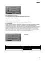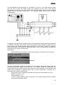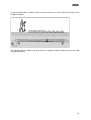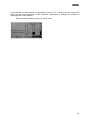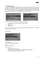
1
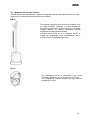
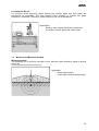
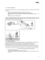
User Manual
Audio Frequency System Locator-Set
TG 20/50, TG 600
UL 30
Ref. No. 822-119
11/2005
BAUR Prüf- und Messtechnik GmbH
Raiffeisenstrasse 8, A-6832 Sulz/Austria
e-mail: [email protected]
internet: www.baur.at
Tel. +43/5522/4941-0
Fax +43/5522/4941-3
2
Guide to this Operating Instruction
For fast finding of important information the
corresponding text passages are marked with symbols
(symbols not stated here are self-explanatory).
More and special information concerning the
respective subject are available from BAUR.
Important information about the
instrument!
In any case, read carefully!
Important information text.
Copyright
© BAUR Prüf- und Messtechnik GmbH, A-6832Sulz / Austria
All rights reserved.
No part of this publication may be reproduced,
transmitted, stored in a data processing system or
translated into another language without the
written permission of BAUR / Sulz, Austria.
In the interest of our customers we reserve the
right for modifications due to technical progress.
Illustrations, descriptions and delivery content are
therefore not binding.
Preface
This manual contains all information necessary for
the correct handling and operation of the
described system. Before using the system please
read carefully these Operating Instructions. If you
have any questions please contact directly:
BAUR
Prüfund
Messtechnik
GmbH,
Raiffeisenstraße 8, A-6832 Sulz / Austria
BAUR Prüf- und Messtechnik GmbH, Raiffeisenstrasse 8
A-6832 Sulz / Austria
Tel.
Fax.
+43/5522/4941-0
+43/5522/4941-3
or refer to your nearest BAUR representative.
3
Safety precautions
The Audio Frequency System is built in accordance
with today’s state of engineering and is safe to
operate. Individual components and the finished unit
are inspected continually by our qualified staff within
the framework of our Quality Assurance Provisions.
Each unit is subjected to thorough testing prior to
shipment. It is imperative to every person who is
involved with the installation, start-up, operation and
maintenance to have read and understood the
complete Operating Instruction. It is the
responsibility of the customer to ensure that only
authorized persons may be allowed to use the unit.
Operators must notify immediately any changes to
the unit that detract from the its safety.
The Audio Frequency System Locator Set is
intended to be used exclusively for route tracing
and fault location of electrical cables and
metallic gas and water pipes.
Any other or additional use is deemed to be in
contravention
of
the
intended
use.
The
manufacturer shall not be liable for damage
resulting from any such use. In such a case the risk
shall be borne solely by the user.
The local safety and accident prevention
regulations are always applicable to the
operation of the unit.
Warranty
At the customer’s written request we undertake to
repair or replace at our discretion and as quickly as
possible all parts that become faulty
as the
demonstrable result of poor material, faulty design
or defective workmanship. We shall bear the costs
of any faulty parts requiring replacement, but not the
costs of transport to us and back to the customer,
nor the costs of packing and insurance! The 12
month warranty time starts from delivery. We shall
not be liable for any damage resulting from normal
wear and tear, improper handling, non-observance
of Operating Instructions and safety regulations. We
shall also refuse to accept any liability if the
customer carries out repairs or changes to the unit
themselves or has others carry them out! The
warranty does not cover damage in transit,
batteries, fuses and any readjustments in
accordance with the Operating Instructions!
We draw attention in addition to the ‘General Sales
and Business Conditions’ of:
BAUR Prüf- und Messtechnik GmbH
Raiffeisenstrasse 8
A-6832-Sulz / Austria
4
Contents
1
Product information
6
2
Description of Locator-Set
7
2.1 Audio Frequency Generator TG 20/50 and TG 600
2.1.1 TG 20/50
2.1.2 TG 600
2.2 Universal Locator UL 30
2.2.1 Menu
2.3 Magnetic and acoustic sensors
2.4 Technical data
8
9
10
11
12
13
15
3
Put TG 20/50 into operation
18
4
Put TG 600 into operation
21
5
Put UL 30 into operation
24
5.1
Startup
24
6
Fault location
25
6.1
6.2
6.3
Acoustic fault location
Distance manhole
Sheath fault
25
28
29
7
Route tracing
33
7.1
7.2
7.3
7.4
7.5
7.6
Connection of frequency generator
Minimum and Maximum method
Depth determination
Terrain examination
Cable identification
Determination of joints (Twist method)
34
35
36
37
37
39
8
Maintenance
41
9
Packing and delivery
43
5
1 Product information
In combination with Surge Voltage Generators (SSG / STG) or Audio Frequency Generators
(TG20/50 and TG600) and accessories like BM 30, earth sticks, the Universallocator UL 30
is used for:
-
pin-pointing of cable faults
route tracing of buried cables or metallic pipes
propagation time measurement
Cable sheath fault location
Combined tracing and pin pointing
With the help of an audio frequency transmitter (TG20/50 or TG600) an electromagnetic field
in the cable is generated.
Depending on selected tracing and measuring methods, the detection is done by an
electromagnetic sensor
The received electromagnetic and acoustic signals are amplified and indicated by the Audio
Frequency Receiver UL 30:
-
acoustically via the integrated loudspeaker or a headphone (to be connected)
optically on the integrated LCD display.
In connection with a Surge Voltage Generator SSG the surge voltage impulse (magnetic
field) is indicated on the pointer UL 30 when performing a coincidence measurement. The
impact noise is heard via headphone of the loudspeaker.
With the propagation time measurement the time difference between magnetic and acoustic
impulse is evaluated. The minimum of the time difference indicates the cable fault position.
Special advantages:
-
at cable faults which acoustically are very difficult to locate, the coincidence
measuring method gives additional help to verify the faulty point.
with cables in pipes the fault position can be located accurately above the cable
route.
6
2 Description of Locator-Set
The Audio Frequency System Locator-Set is used for route tracing and fault location of:
-
electrical cables
metallic gas and water pipes.
Functions and procedures
With the help of an audio frequency transmitter (TG20/50 or TG600) an electromagnetic field
in the cable is generated. The field is detected by sensors (e.g., detecting rod SP 30,).
The signal is amplified by the audio frequency receiver UL 30 and indicated acoustically via a
headphone or a loudspeaker or optically on the display.
Fields of application
With its various sensors and by selecting specific tracing and measuring methods a wide
range of applications is possible:
-
Routing of cables and metallic pipes
Depth determination of cables and metallic pipes
Cable selection
Cable detection even on live cables and lines
Location of cable joints and branches
Accurate pin-point fault location according to the BAUR twist method in conjunction
with the powerful Audio Frequency Transmitter TG20/50 or TG600.
Accurate pin-point fault location in conjunction with the Surge Voltage Generator
SSG.
Accurate pin-point fault location in piped cables by application of the acoustic
propagation time measurement.
7
2.1
Audio Frequency Generator TG 20/50 and TG 600
Audio Frequency Generator TG 20/50
Description TG 20/50
The Audio Frequency Transmitter Locator TG
20/50 is a powerful, battery operated instrument
with an integrated power supply unit. An output of
50 VA is available during mains operation and
therefore application for accurate pin-point fault
location on twisted multi-core cables is possible.
As well, cable tracing can e done.
Audio Frequency Generator TG 600
Description TG 600
The Audio Frequency Transmitter Locator TG 600 has
been special designed for the pin-pointing location of
cable faults and joints.
Due to indication of input and output current, selection
of the correct adjustment is facilitated.
Beside the use for cable fault location, also high
frequency burn down processes can be carried out,
particularly on signal or telecommunication cables.
The maximum output current can be switched
between 60VA and 600VA.
8
2.1.1
TG 20/50
3
15
7
9
8
6
2
14
5
10
1
13
4
13
11
12
Display elements:
1 Power control
2 Charge control
3 Pointer instrument for Iout and Iin and battery control
4 Indication of impedance level
Operating elements:
5 ON switch and mode selector
6 Button for battery control and instrument illumination
7 Button for indication of Iin
8 Button for switching measuring range x 0.1 for Iout
9 Button for automatic or manual impedance adjustment
10 Regulating switch for output current
Interfaces:
11 Mains connection
12 Connection for external battery
13 Output socket
14 Protective earth terminal
15 Connection for loop antenna
9
2.1.2
TG 600
18 17 16 4
4 6 8 10 2 3 14
15
1 5,7,9,11,20,19,12 13
Display elements:
1 Input current of adjusting transformer
2 Output current of adjusting transformer
3 Overtemperature indication
Operating elements:
4 Mains ON
5 Mains OFF
6 Frequency selection 2 kHz
7 Frequency selection 10 kHz
8 Continuous operation
9 Impulse operation
10 Output power 60 VA
11 Output power 600 VA
12 Impedance selector switch Zi
13 Power control
14 Measuring range selector for output current
15 Push-buttons for compensation capacitors
Interfaces:
16 Mains connection
17 Protective earth terminal
18 Output sockets
19 Fuse F1
20 Fuse F2
10
2.2
Universal Locator UL 30
Input sockets for sheath
fault sticks
Display
Up – for navigation
or increase
Backlight
Switch button
Left – for navigation or
decrease
Right – for navigation
or increase
Down – for navigation
or increase
OK
ON / OFF button
Loudspeaker
Headphone outlet
Socket for BM 30 / SP 30
Removable rear cover
with battery compartment
11
2.2.1 Menu
A application-oriented menu structure allows fast and easy operation of the UL 30. At main
menu the application could be selected. The following submenus contain the special fault
location- respectively tracing methods.
Fault location:
Route tracing:
Setup:
12
2.3 Magnetic and acoustic sensors
Several sensors are available for reception of magnetic and acoustic signals which are used
depending on selected tracing and measuring method.
BM 30
The highest sensitivity of the ground microphone is at
the range of 200Hz. Therefore, it is most suitable for
pin-pointing of flashover faults according to the Surge
Voltage method. Its special decoupled housing
suppresses possible ambient noises.
Included into the BM 30 is a magnetic sensor to
enable the propagation time measurement and a
tracing of cable line while pin pointing.
KH 30
The headphone KH 30 is connected to the Audio
Frequency Receiver via a 3-pin jack plug (6.3mm).
For suppressing ambient noises the type KH20/S
headphone is used.
13
SP 30
The detecting rod consists of a searching coil
adjusted to an oscillating circuit by condensers. Using
the switch on the handle of the detecting rod the
frequency can be adapted to the signal frequency of
the Audio Frequency Generator. The hinged
searching coil can be turned by 45° or 90°. The 45°
position is used for determination of the depth of
buried cables.
14
2.4
Technical data
Audio Frequency Generator TG20/50
Output power
0 - 50VA in mains operation
0- 20VA in battery operation
Output current
max. 8 A
Output impedance
in 7 steps
1 / 3 / 10 / 30 / 100 / 300 / 1000 W
with automatic adaptation
Frequencies
2 frequencies, switchable
standard: 2kHz and 10kHz
other frequencies optionally
480 Hz
800 Hz
1030 Hz
1090 Hz
1350 Hz
1450 Hz
2000 Hz
Df - ± 0.1 %
k-faktor k - 1,5 % at 4 VA
9820 Hz
10000 Hz
12000 Hz
Df - ± 0.1 %
k-faktor k - 3 % at 4 VA
Operating modes
Continuous operation and impulse operation
Display
Illuminated instrument with indication of Iout (in A); switchable via button Iin
(in A);
Battery test
Indication of impedance levels with LED
Output
Non-contacting pole terminals (safe from contact) and socket for loop
antenna on side cover
Power supply
Mains connection
110/120, 220/230, 240 V, 50-60Hz
Power consumption
150VA at 50VA output power
Internal lead acid battery 12V / 9.5Ah
External battery
12V - 24V (reverse battery protection)
Charging unit
Overcharge protection
80% of battery capacity is reached within 14 hours; when in mains supply,
charging is made in all operating modes
Low level discharge
protection
Unit is switched off before battery is completely discharged
Operating time battery
at 20VA approx. 2.5 hours
Operating temperature
-20°C to +50°C
Dimensions
290 x 130 x 250 mm
Weight
approx. 9.5 kg
15
Audio Frequency Generator TG 600
Output power
at 2 kHz in 2 steps 600VA / 60VA
at 10kHz in 2 steps 450VA / 45VA
Output current
max. 30 A
Output impedance
in 8 steps
0.3 / 0.8 / 1.8 / 4 / 10 / 30 / 100 / 300 W
Frequencies
Quarz-stabilized: 2kHz and 10kHz;
other frequencies on request
Operating modes
Continuous operation and impulse operation
Display
2 instruments for indication of Iin and Iout
Reactive power
compensation
adjustable in 63 steps
Power supply
110/120, 220/230 V, 50-60Hz
Power consumption
1800VA at 600VA output power
Overload protection
Overtemperature switch-off and indication
Operating temperature -20°C to +40°C
Dimensions
505 x 255 x 330 mm
Weight
approx. 38 kg
16
Universal Locator UL 30
Receiving frequency
50Hz – 10kHz, 815Hz, 2kHz, 10kHz
+ 2 additional frequencies on request
Filter
digital
Üassive reception
50/60Hz mains signal
amplification
0-38 dB
propagation velocity range
0-96ms
operating temperature
-20°C….+55°C
protection
water- and dust protected
power supply
4x1.5V cells (IEC LR 6)
battery life
(normal operation)
approx. 50h
weight
550g
17
3 Put TG 20/50 into operation
Operating the Audio Frequency Transmitter TG20/50 either
with mains supply (110/120V, 220/230V or 240V / 50Hz or 60Hz), output power of
50VA
- via an internal battery (for mobile use), output power approx. 20VA
- via external battery (12V to max. 24VDC)
Remark: Pay attention to correct polarity (+ red, -black)!
-
Designed for continuous operation
In all operating modes the unit is designed for continuous operation. The output power of
50VA is only reached with:
-
mains operation or external battery operation (with 24VDC)
optimum adjustment.
During mains and battery charging operation, please observe that:
The voltage setting of the mains voltage socket must correspond to the local mains voltage!
Carry out battery test
The integrated battery (=lead-acid battery) is protected by a low discharge protection circuit
causing the TG20/50 unit to be switched off at a discharge voltage of 10.5V.
Before each mobile use and battery operation, please check the battery state of charge.
Check state of charge using control button
Charge battery
If pointer of instrument is below the marked range:
-
Connect TG20/50 to mains the charging control lamp „charge” lights up. The
is charged by the built in charger (with an overload protection).
General battery charging time should be at least 12 to 14 hours!
battery
The TG20/50 unit can also be used during the battery charging process. That means, the
integrated battery is also charged during each mains operation.
☞
Do not store lead acid battery in a discharged state. Charge the battery all 14 days during the
night!
18
Connection of Audio Frequency Generator
Connecting the TG20/50 unit is made either via the output sockets “output” (galvanic con.),
the clip on device AZ 10 or the loop antenna RA 10
U = 0V !!
Do not connect live cables and lines (e.g. interference noises, mains pick-ups) to the sockets
‘output’! Danger of unit destruction!
Before connection, always check if line is zero potential!
Carry out galvanic or inductive connection
1
2
2a
2b
3
4
Carry out either
step 2a or 2b
Switch on
Audio Frequency
Generator
Step
Procedure
1
Connect earth lead.
2a
Make galvanic connection: Connect a dead
cable/line to the two black sockets ‘output’.
2b
Make inductive connection: Remove side cover
and connect loop antenna.
3
Turn output regulator completely to the right stop.
Observe max. permissible voltage of connected
line.
4
Set mode selector to the desired operating
frequency. Power Control lamp lights up.
19
Carry out automatic or manual load adaption
1a,1b
2
4
3
Condition for automatic load adaption:
-
output current Iout > 10mA!
Make a manual load adjustment at:
-
high impedance load
Carry out automatic (1a) or manual (1b) load adjustment
Step
Procedure
1a
Press button to pos. „auto“.
If an LED of the impedance adjusting level lights up:
- the output impedance is adjusted
- a voltage is on the „output“ sockets
1b
Press button to pos. „man“ as long as the desired adjusting level is reached.
2
Adjust desired output current using the output regulator.
3
Press button Iout = instrument range is switched to 1A.
4
Press button Iin. The current consumption of the amplifier is indicated. With battery
operation:
Iin=3A-battery 9Ah=approx. 3 hours of operating time
Audio Frequency Generator TG20/50 is ready for operation.
Overload protection
The power output stage of the TG20/50 unit is protected by a terminal circuit breaker.
After a switch off:
-
using the mode selector - switch on again after a certain cooling period
20
4
Put TG 600 into operation
The TG600 unit a power generator
The TG600 unit is designed for cable fault location according to the twist method. At a output
frequency of 2 kHz, the power is 600VA at 10kHz 450 VA.
The operation can only be done on mains (220/ 230 V; 50/ 60Hz or 110/ 120 V).
Only for mains operation
The Audio Frequency Transmitter TG600 is only operating:
-
with mains supply 220/230V ; 50Hz (110/120V ; 60Hz)
Connection of TG600
3
-
-
1
2
Do not connect live cables and lines
(e.g. interference noises, mains pick-ups) to the
sockets ‘output’! Danger of unit destruction!
Before connection, always check if line is clear
of voltage!
Connection
Step
Procedure
1
Connect earth lead.
2
Connect mains cable.
3
Connect output lines.
21
Set Audio Frequency Generator
5 4
3
21
Proceedings
Step
Procedure
1
Turn power control to „0“ (0 left limit stop).
2
Set impedance selector switch to Zi = 0.3 W.
3
Select max. output power with button „60VA“ or
„600VA“.
4
Select output frequency with button „2kHz“ or
„10kHz“.
5
Switch on unit by pressing button „ON“.
TG600 is ready for operation.
Impulse operation
By switching, the TG600 unit can be operated at 2kHz
and at 10kHz. As a result, the detecting signal can be
distinguished from the interfering signal easier.
Do not apply with twist method.
Operation with reduced power
For most fault location methods (e.g. twist method) a
highest possible current in the cable is advantageous.
When tracing cables (route determination) and
especially for cable selection, current induction from
adjacent lines must be avoided.
In such cases, an output power of approx. 1VA to max.
100VA is sufficient.
Max. output voltages
Impedance level Zi
0,3
1
3
10
30
100
300
Ω
Output voltage
34
52
78
122
207
370
660
V
Overload protection
At an output current Iout>30A the output power is switched automatically to 60VA. In this
case, turn back power control and switch back again to max. output power 600VA.
22
Overtemperature switch off
In case of overloading the T600 unit:
-
an optical indication is given by the LED „T>“
-
the output power is turned down until power output stage is cooled down.
Carry out load adaption
4
2,6
1,5
3
Proceedings
Step
Procedure
1
Set load selector switch to Zi = 0.3 Ω
2
Switch off all compensation capacitors. Bulbs do
not light up.
3
Adjust input current Iin using power control
regulator.
At an output frequency 2 kHz:
At an output frequency 10 kHz:
Iin < 28 A
Iin < 21 A
4
Read output current Iout.
5
Increase value of load selector switch until the
output current Iout reaches a maximum at a
constant input current Iin (eg, 5A).
6
Carry out reactive power compensation.
Starting with button 1, connect capacitors until
input current Iin reaches a minimum.
23
5 Put UL 30 into operation
5.1
Startup
For operation switch on the UL 30 with the ON / OFF button. The UL 30 performs a selfand battery test.
With the selection of Last you are switched to the working plane which was used the last
time. With <- in the working plane you are entering the main menu. Here a selection of fault
location, route tracing and setup is possible.
The display and working of measurement is divided into two planes. A special SwitchButtonallows the fast changing between working- and config plane. The first plane the so
called “working” plane shows the important figures and allows necessary adjustments which
are often needed. The second plane “config” plane shows all adjustable parameters of the
selected measuring method.
Only after activating the switch button changing of parameter
settings are saved. At a newly recall with "Last" the new
settings are active!
The menus of acoustic location are taken as example:
Working plane:
Press SWITCH – Button!!!
Konfig plane:
Press SWITCH – Button or <- !!!
Switch back to working plane.
24
6 Fault location
At menu FAULT LOCATION following methods are selectable:
-
6.1
Last (switch to last measurement with related settings)
Acoustic location
Distance manhole
Sheath fault
Acoustic fault location
For the acoustic fault location according to the Surge Voltage
method a Surge Voltage Generator SSG and a ground
microphone BM 30 is necessary additionally.
25
Working plane:
Level
signal
of
Distance
fault
acoustic
to
The parameters “magnetic signal [Magn.]”, “Filter to avoid noise [Filt.]” and “sensitivity of
microphone [gain]” can be changed during measurements and can easily be adjusted. The
black framed parameter indicates the status (gain is active in the example) Pressing the up
or down button allows to adjust the levels.
Konfig Plane:
Magnetic signal:
Adjustment of magnetic signal sensitivity with the right/left buttons. The bargraph shows the
present level of sensitivity. In case of magnetic signal receipt a * symbol or number is
displayed.
Volume Speaker:
Adjustment of headphones volume
Gain Microphone:
Adjustment of microphone sensitivity. The bargraph shows the current gain. If
groundmicrophone is lifted up from ground the microphone is switched soundless
automatically. Putting on the device again the signal will be heard after a delay of one
second.
Filter Frequency:
Adjustment of filter frequency in various steps between 100Hz and 1kHz. This allows a
effective rejection of noises and interferences. The adjusted frequency is displayed. Default
setting is OFF.
26
Magnetic signal:
The impulse current flowing into the cable while SSG operation for pin pointing creates a
magnetic field around the cable. This magnetic signal is used to start the propagation time
measurement. In case of weak breakdown noise or strong ambient noises the magnetic
signal can help to evaluate the acoustic signal better.
The unit:
-
shows if the Surge Voltage Generator is working properly
determines the moment when a breakdown noise is to be expected
indicates, via the signal intensity, if you are going in direction to or from the cable
route.
Propagation Time Measurement:
With the propagation time measurement the time difference between receipt of the magnetic
and the acoustic impulse is evaluated. Above the fault location the time difference is at
minimum. Carry out 2 to 3 measurements with the UL 30 unit at each measuring point with
the same setting. The results should not show too much deviation. Then you can be sure that
the measurement is correct and no faulty triggering has occurred due to ambient noises.
The time measurement is started by the magnetic impulse and will be stopped by the
acoustic signal. To get save results the UL 30 only takes the measurement as good, if the
two signals are in a defined time frame and the acoustic signal is clearly identified. (clearly
identification of acoustic signal if it is higher than the ambient noises).
In case of non clear identification the display is showing # # # #. Through increase of
acoustic gain it could be possible to get valid measurement. Also the filter adjustment could
help to reduce the influence of ambient noises.
27
Tracing with BM 30
The parallel menu allows a determination of cable route. The black stripe at the housing of
microphone shows the parallel direction of cable route.
Enter the parallel menu through pressing OK on Magnetic Signal.
Rotate the BM 30 on his own axe. The Ratio bargraph is changing. Try to detect the
maximum. If maximum of bargraph found the black stripe is parallel to the cable.
Attention: Pipes in earth as well as metallic objects on surface could affect this method. In
worst case results could be inverted.
6.2 Distance manhole
If no breakdown can be heard from a cable within a pipe (over a bridge or similar buildings)
the distance manhole method has be done.
Choose „Distance manhole“ in „acoustic location“ menu and follow step by step the displayed
instruction.
28
First measurement on first shaft:
2-3 measurements to get a valid result (at example above 54,5m)
Insert distance (200m , steps etc.)
Second measurement on second shaft
2-3 measurements to get a valid result
As result the distance to fault from second shaft is displayed. (145,5m)
6.3 Sheath fault
Today’s customary method to locate sheath faults is the modificated "Wurmbach" procedure.
A impulse sequence (SSG) or a impulse block (STG) is sent to the cable under test.
The voltage drop at the fault location results in a step voltage which is indicated in the UL 20
with help of cable sheath fault sticks. The UL 30 displays via bargraph and an arrow (drag
indicator) the direction to the fault. The drag indicator shows the direction to go until the
next impulse has taken place. Additional to the optical display a accoustic information with
different tone signals is given. Ahead the fault the bargraph indicates zero.
▼
Deflection
Right
Left
Acustic
Right
Left
Peak hold
0
0
29
If a cable sheath has several faults, e.g. 2 between 1 k. and 5 k., all 3 faults can be located
with the STG or SSG and KMF1 during one passage over the route. This requires
appropriate practice and one should know that the step voltage shows several passings
through zero (5 passings through zero). The following sketch should serve for better
understanding.
In opposite to the pin pointing methods above, the twist method needs a frequency generator
(TG 20/50 or TG 600) and a search coil SP 30 instead of SSG and BM 30. When using the
twist method, the highest possible power adjustment of the Audio Frequency Generator
should be observed. The higher the obtainable output current of the generator, the better the
twist effect on the surface can be heard.
Applications:
-
Cable selection, determination of joints, fault location on multicore lines and cables
The twist method offers particular advantages for low voltage and signal cables, where the
maximum permissible voltage is less than 1kV. The cable is loaded only slightly and the
route tracing and the location itself can be carried out in one operation. As an example, fast
results can be obtained in lighting cables and in house connections. Conditions for a
successful twist method measurement:
-
Faulty cores must be stranded or pitched and must not be screened one by one.
Distance of cores < 3 cm
Fault resistance < 3 Ω
In case of contact between fault and ground, any existing sheaths must be released
from ground (stationary earth).
30
To get a twisting field, a healthy core is used as inverse wire. At the other end a short-circuit
bridge is installed.
The twisting field is located until short-circuit is reached. Directly behind the fault the field
strength decreases.
31
A special filter for twist method is integrated into the UL 30. It filters the basic noises and
uses only the real oscillations for fault detection. Adjustment of settings are possible at
working plane of twist method.
-
Select suitable oscillation pick up by using Zoom
32
7 Route tracing
Tracing is always possible as active or passive. If a cable is live, the harmonics of the mains
frequency can be heard as ‘mains hum’. However, all grounded conductors, water pipes and
parallel running cables which are connected to the 50Hz mains system also have this ‘mains
hum’. To avoid confusion, it is recommendable to disconnect conductor and feed cable
inductively by using Audio frequency generator to do a active tracing.
At menu ROUTE TRACING following methods are selectable:
-
Last (switch to last measurement with related settings)
Route Tracing
Depth
Twist method
Also at route tracing the device is working with working- and config plane. At this planes
following settings are possible.
Working plane:
Volume Speaker:
Loudness of loudspeaker adjustable
Gain:
Sensitivity of search coil.
Filter Frequency:
-
50 / 60 Hz for passive tracing
815Hz, 2kHz and 10 kHz depends on sending frequency generator
two additional frequencies adjustable at setup.
33
7.1 Connection of frequency generator
If this method can be used, galvanic coupling is always the best method.
Application:
-
for cable routing
By direct galvanic connection the highest possible
ranges can be obtained.
Do not increase current unnecessarily because
adjacent lines might otherwise be induced too.
The inverse current is conducted via earth. Please note, that this connection method can
cause fault measurements if used on underground lines (e.g., in residential or industrial
areas), because the inverse current is also conducted via other cables and lines which are
located by the UL 30 unit with a very strong audio frequency signal.
Clip on device AZ 10
The clip-on device can be used with dead and live cables.
Applications:
-
Routing
(house
telephone, gas)
connection,
water,
Connection directly on the Audio Frequency Generator. Maximum load of clip-on device
approx. 30VA. The highest efficiency is reached by applying the clip-on device in the middle
of the cable.
34
Loop antenna RA 10
For inductive audio frequency signal feeding into metallic pipes and lines which are
galvanically no accessible. Turn loop antenna RA10 vertically or inclined. Set Audio
Frequency Transmitter TG20/50 to 10kHz frequency and 300 Ω impedance.
Applications:
-
Routing, cable tracing and terrain examination
for location of water pipes with rubber joints
7.2 Minimum and Maximum method
Minimum method
The detecting coil is vertical to the path of line. Minimum audio frequency signal is directly
above line.
Application:
-
depth determination
exact cable tracing and pinpointing
35
Maximum Method
Detecting coil is horizontal to path of line. Maximum audio signal is directly above line.
Application:
-
for cable routing
for terrain examination
The picture beneath shows the working plane of maximum method.
7.3 Depth determination
For measuring the depth (d) of a conductor!
- first determine the exact path of the cable
- subsequently, place coil of detecting road at 45°C
The minimum audio-frequency signal is heard at the depth “d” at a corresponding distance
from the path of the cable.
36
7.4
Terrain examination
To examine a particular area for existing cable/pipes systems we recommend the following
procedure:
-
Divide the area in question into squares of approx. 25 x 25 m.
Set up the Audio Frequency Generator in the centre of the cable run.
Set ground rods into the ground to the left and right of the generator at approx. 12 to
15m.
Keep output power of generator low.
If there is a metallic conductor within the set out area, it will propagate a magnetic field in its
vicinity. The magnetic field has in most cases the shape of a single-sided maximum; e.g. with
a steep edge to the audio frequency waveform.
7.5 Cable identification
As this method requires a high technical knowledge for cable identification, the use of a the
special instrument KSG 100 is recommended. To prevent possible accidents due to
inappropriate handling or misinterpretation of the cable selection, it is generally
recommended to use cable cutters according to EN 50340 and/or a cable shooting devices.
The local safety and accident precaution instructions are always applicable, and mandatory.
If a cable is to be picked out of several in a cable duct (e.g., cutting for a house connection):
- disconnect the desired cable at all end points
- sheath remains grounded
- connect two wires with each other at one end point
- connect Audio Frequency Generator across 2 short-circuit wires and set current to 0.1
to 0.5 A.
37
Using the UL 30 unit at the open cableway the twist of the conductor is traced:
- set searching coil parallel to the cable
- move slowly over the cable to be traced
The twist signal is only received from the cable supplied with current from the Audio
Frequency Generator. In case of scattering:
-
reduce feed current.
-
Cable selection with selecting coils AS2/30, AS10/30
38
With closely picked cables:
-
use selecting coil AS2/30
In case of interference frequencies at 2kHz:
-
use selecting coil AS10/30.
For cable selection of live cables:
-
feed in audio-frequency signal via separating filter or clip-on device AZ10
use selecting coil AS10/30.
7.6 Determination of joints (Twist method)
Also for this application the search coil SP 30 is used. A signal of a frequency generator is
sent to the cable. Therefore joints can be determined with the SP 30. The field strength is
amplified by sleeves and branches enabling a accurate pin-pointing of their location.
39
The joint determination basics on a twist method similar principle. Therefore the special filter
for twist method is again integrated into the UL 30. It filters the basic noises and uses only
the real oscillations for fault detection. Adjustment of settings are possible at working plane of
twist method.
40
8 Maintenance
Within this section find all necessary information concerning repair and maintenance works.
UL 30 – change of batteries
Empty battery status will be displayed approx. 30 min before switching off.
-
Open battery case
Battery type: 4 x 1.5V Mignon, AA, LR 6
Change batteries (watch polarity)
Close battery case
Check function of UL 30
41
Replace fuses of Audio Frequency Generator
In case of unit switch off due to fuse tripping: Only insert new fuses with
the specified rating!
Audio Frequency Generator TG20/50
F1
F2
Set mains voltage
F1
F2
(Ø 6.3 x 30 mm)
110 V / 120 V T4A/250V
T4A/250V
220 V / 230 V T2A/250V
T2A/250V
240 V
T2A/250V T2A/250V
Internal fuse F1: T8A/250V (Ø 5 x 20 mm)
Audio Frequency Generator TG600
F2 F1
Set mains voltage
☞
F1
F2
(Ø 5 x 20 mm)
110 V / 120 V T16A/250V
T16A/250V
220 V / 230 V T8A/250V
T8A/250V
Internal fuse F3, F4: T0.5A/250V (Ø 5 x 20 mm)
Depending on set mains voltage insert specified fuses.
42
9 Packing and delivery
If units are not used immediately, always store them in the carton and in dry rooms!
Complains concerning damage should be made to us by the purchaser without delay after
receipt of the shipment using a standard damage certificate.
Confirmation in writing of externally visible damage should be obtained from the carrier
immediately. The extent and probable cause of the damage should be stated as well.
For damage which is discovered during unpacking the responsible transportation company
should immediately be requested verbally and in writing (registered letter) for loss
assessment and should be made responsible at the same time!
We also refer to our “General Sales and Business Conditions”.
BAUR Prüf- und Messtechnik GmbH,
A-6832 Sulz / Austria
43