1
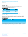
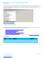
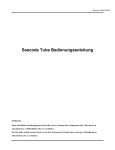
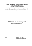
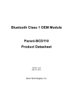
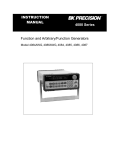
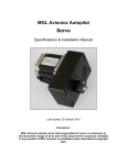
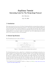
Development Kit for BT800 - Bluetooth v4.0 USB HCI module Application Note v1.0 Part # DVK-BT800 Applicable to the following Bluetooth module part numbers: BT800 Revision 1.0 onwards OVERVIEW Laird’s Development Kit (DVK-BT800) provides a platform for rapid prototyping of wireless connectivity options for BT800-series modules through a USB interface attached on customer platforms. This manual is for the development PCB which is DVK-BT800 R1.0 on PCB. Introduction The Laird DVK-BT800 is designed to support the rapid development of applications and evaluation for the specific Laird Bluetooth module part number BT800. In depth documentation for this product is available at: www.lairdtech.com/Products/Embedded-Wireless-Solutions/Bluetooth-Radio-Modules/BT800-Series/ Package Contents Each DVK-BT800 includes the following items: Development Motherboard The motherboard has the BT800 module already soldered onto it and it exposes all the various hardware interfaces available. USB cable – The USB cable can be used to power, control, and configure the BT800. USB A Type Male to USB A Type Insert Card Provides links to additional information including the BT800 User Manual, Utilities, Schematics, Quick Start Guides and more. DVK-BT800 – Main Development Board The development board allows the Laird Bluetooth module to be connected to a PC. The development board provides USB interface linking to the PCB and the BT800 host interface. Bluetooth driver is automatically installed when the development board is plugged into a PC running Microsoft Windows. Windows 8 provides native support of BT 4.0. Windows 7 and XP provide native support of BT 2.1 and BT 2.0 respectively. The development board is recognized as “Generic Bluetooth Adapter” in Windows Device Manager. Americas: +1-800-492-2320 Option 2 Europe: +44-1628-858-940 Hong Kong: +852-2923-0610 www.lairdtech.com/bluetooth 1 Laird Technologies BT800 Bluetooth 4.0 Dual mode module Development Kit (DVK-BT800) Application Note GETTING TO KNOW THE DEVELOPMENT BOARD I/O voltage (1.8V/3.3V) selection PCM or SPI mode selection USB PCM/SP I BT800 module Reset PIO (0;1;2;5)/3-wire Coex. Figure 1: Main DVK-BT800 Board POWER SUPPLY The Power Supply voltage for the BT800 DVK is shown in Table 1. Table 1: BT800 DVK Power Supply voltage Input Voltage Minimum Typical Maximum 4.5V 5V 5.5V /8 The developer kit includes a USB cable to provide power to the development board. This should be plugged into a PC USB port, a USB hub, or a mains adapter with a USB output. If a hub is used, it should be a powered USB hub to ensure that sufficient current is available at the port being used. The BT800 module can be driven by the current available at a USB port. The low noise LDO (U2) on the DVK-BT800 provides the 1.8 V out to support the I/O voltage configuration. Americas: +1-800-492-2320 Option 2 Europe: +44-1628-858-940 Hong Kong: +852-2923-0610 www.lairdtech.com/bluetooth 2 Laird Technologies BT800 Bluetooth 4.0 Dual mode module Development Kit (DVK-BT800) Application Note INTERFACE SPECIFICATION Pin Header – CON2 The DVK-BT800 provides the PCM or SPI mode on CON2 which is configured through S1 (see Fig2.) The pin descriptions of CON2 in PCM/SPI mode are shown in Table 2. Table 2: CON2 pin descriptions CON2 Description (PCM/SPI) Direction Pin-1 Pin-2 Pin-3 Pin-4 Pin-5 PCM_IN/SPI_MOSI PCM_CLK_SPI_CLK PCM_OUT/SPI_MISO PCM_SYNC/SPI_CS# GND Input I/O Output I/O - Customers can configure the PCM or SPI for various methods of operation via CSR’s PSTools. Pin Header – CON3 There are four PIO signals (PIO-0, PIO-1, PIO-2, PIO-5) presented on CON3. These four PIOs can be used for LED indication or Wi-Fi and BT coexistence. The default setting on the BT800 is to support Wi-Fi and BT coexistence. Detail descriptions are listed in Table 3. Table 3: CON3 Pin descriptions CON3 Description Direction Pin-1 Pin-2 Pin-3 Pin-4 Pin-5 WLAN_ACTIVE (Default) Or PIO-0 BT_PRIORITY (Default) Or PIO-1 BT_ACTIVE (Default) Or PIO-2 PIO-5 GND Input Output Output I/O - An input to request the pre-emption of Bluetooth activity. An output to indicate packet priority and transfer direction An output to indicate Bluetooth activity Not used. Leave it unconnected. There are two LED indicators on the DVK-BT800. The LED1 (D2) is controlled by BT_PRIORITY/PIO-1 and the LED2 (D3) is controlled by WLAN_ACTIVE/PIO-0. In the default PSkey setting (enable Wi-Fi and BT coexistence mode), LED1 is always ON and LED2 is always OFF. Americas: +1-800-492-2320 Option 2 Europe: +44-1628-858-940 Hong Kong: +852-2923-0610 www.lairdtech.com/bluetooth 3 Laird Technologies BT800 Bluetooth 4.0 Dual mode module Development Kit (DVK-BT800) Application Note Figure 2: S1 and S2 settings PUSH BUTTON and SWITCH Configuration Switch S2 on the DVK-800 is used to select I/O voltage level between 1.8 V or 3.3 V). This allows you to select a suitable I/O signal voltage level when connecting the DVK-BT800 to your platform. S3 (push button TACT switch) provides a reset signal to reset the BT800 module. Table 4: Push button descriptions Push Button S1 S2 S3 Label on DVK-BT800 PCB PCM SPI +3V3 +1V8 Reset Description Select the PCM or SPI mode on CON2 Select the I/O voltage to 3.3V or 1.8V Reset the BT800 module PSKEYS CONFIGURATION PSkeys for various functions such as LED status or WLAN coexistence may be configured via USB or SPI interface. For SPI interface, a USB-SPI adapter is required. For USB interface, a special USB driver is required. BlueSuite, a utility by Cambridge Silicon Radio, must be installed on the PC as well. This section covers how to install the SPI adapter, and the special USB driver only. For the exact procedure using BlueSuite’s PStools over these interfaces, please refer to the BT800 WLAN Coexistence and LED Status application note. Installing CSR USB driver When the BT800 development board is first plugged into the PC USB port, Windows installs the driver automatically. It is recognized as the “Generic USB Adapter” in the Windows device manager (Figure 3). Americas: +1-800-492-2320 Option 2 Europe: +44-1628-858-940 Hong Kong: +852-2923-0610 www.lairdtech.com/bluetooth 4 Laird Technologies BT800 Bluetooth 4.0 Dual mode module Development Kit (DVK-BT800) Application Note Figure 3: Generic Bluetooth Adapter in Device Manager Complete the following steps to install the CSR USB driver: 1. Right-click on Generic Bluetooth Adapter, then click Update Driver Software. Figure 4: Contextual Rollout 2. Select Driver tab and click Update Driver. Figure 5: Update Driver button in Properties panel 3. Click Browse my computer for driver software. 4. Click Let me pick from a list of device drivers on my computer. 5. Click Have Disk. Figure 6: “Have Disk" button Americas: +1-800-492-2320 Option 2 Europe: +44-1628-858-940 Hong Kong: +852-2923-0610 www.lairdtech.com/bluetooth 5 Laird Technologies BT800 Bluetooth 4.0 Dual mode module Development Kit (DVK-BT800) Application Note 6. Navigate to where the CSR driver is located on your computer, and select CSRBlueCoreUSB.inf. Proceed through the windows until software installation is complete. Figure 7: CSR USB Driver installation The BT800 development board is now recognized as CSR BlueCore Bluetooth in Windows device manager. It can be found by expanding Universal Serial Bus controllers. Americas: +1-800-492-2320 Option 2 Europe: +44-1628-858-940 Hong Kong: +852-2923-0610 www.lairdtech.com/bluetooth 6 Laird Technologies BT800 Bluetooth 4.0 Dual mode module Development Kit (DVK-BT800) Application Note Figure 8: CSR BlueCore Bluetooth in Device Manager If you are not planning to use the SPI adapter, you can skip to Open PStools. CSR USB-SPI Adapter The USB-SPI adapter comes with an RJ45 cable. Cut the RJ45 cable in halves. Plug in the RJ45 jack to the adapter and connect the opened end to the development board. Figure 7: CSR USB SPI adaptor Table 5 details RJ45 pins and their corresponding SPI signals. Table 5: RJ45 to SPI wiring Signal RJ45 Connector Pin SPI_CS8 1 SPI_MOSI 5 SPI_CLK 7 SPI_MISO 3 GND 8 Americas: +1-800-492-2320 Option 2 Europe: +44-1628-858-940 Hong Kong: +852-2923-0610 www.lairdtech.com/bluetooth 7 Laird Technologies BT800 Bluetooth 4.0 Dual mode module Development Kit (DVK-BT800) Application Note Figure 8: Wire numbering in RJ45 jack Open PStools After invoking PStools, customers must select either USB transport or SPI transport to access the PSkeys. On the BT800 DVK board, there is a 10-pin header for SPI and WLAN Coexistence, and SPI/PCM switch. If SPI interface will be used for opening PStools, set the SPI/PCM switch to the SPI position before connecting the board to your PC. Figure 9: BT800 DVK Board, SPI/PCM switch set to SPI In PStools, select either USB or SPI transport as shown in Figure 10 and Figure 11. Figure 10: Selecting USB transport Figure 11: Selecting SPI transport Americas: +1-800-492-2320 Option 2 Europe: +44-1628-858-940 Hong Kong: +852-2923-0610 www.lairdtech.com/bluetooth 8 Laird Technologies BT800 Bluetooth 4.0 Dual mode module Development Kit (DVK-BT800) Application Note PStools first reads all the PSkeys from the module. This process takes about 10 seconds, and then the screen in Figure 12 appears with “Bluetooth Address” highlighted on the list, and MAC address shown on the right. The Bluetooth address of your module will be different. The address is unique. Do not attempt to change it, or you might put the module in nonoperational condition. Figure 12: PStools opened successfully ADDITIONAL DOCUMENTATION Laird offers a variety of documentation and ancillary information to support our customers through the initial evaluation process and ultimately into mass production. Additional documentation includes: BT800 WLAN Coexistence and LED Status Application Note BT800 Development Kit Application Note BT800 Hardware Integration Guide BT800 – Class 1 BT4.0 Dual Mode HCI module – Datasheet BT800 and Linux / Android Quick Start Guide For queries or to receive local support for the DVK-BT800 or BT800 module, contact [email protected] REVISION HISTORY Revision Date 1.0 5 Sept 2013 Description Initiated By Initial Release Americas: +1-800-492-2320 Option 2 Europe: +44-1628-858-940 Hong Kong: +852-2923-0610 www.lairdtech.com/bluetooth Jonathan Kaye 9 Laird Technologies