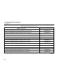
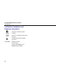
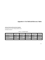
1
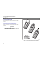
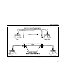
DTX-MFM2/GFM2/SFM2
Fiber Modules
Users Manual
PN 2142235
April 2004, Rev. 3 5/07
© 2004, 2006, 2007 Fluke Corporation. All rights reserved. Printed in USA.
All product names are trademarks of their respective companies.
LIMITED WARRANTY AND LIMITATION OF LIABILITY
Each Fluke Networks product is warranted to be free from defects in material and workmanship under normal use and service. The warranty
period for the mainframe is one year and begins on the date of purchase. Parts, accessories, product repairs and services are warranted for
90 days, unless otherwise stated. Ni-Cad, Ni-MH and Li-Ion batteries, cables or other peripherals are all considered parts or accessories. The
warranty extends only to the original buyer or end user customer of a Fluke Networks authorized reseller, and does not apply to any product which, in Fluke Networks’ opinion, has been misused, abused, altered, neglected, contaminated, or damaged by accident or abnormal
conditions of operation or handling. Fluke Networks warrants that software will operate substantially in accordance with its functional
specifications for 90 days and that it has been properly recorded on non-defective media. Fluke Networks does not warrant that software
will be error free or operate without interruption.
Fluke Networks authorized resellers shall extend this warranty on new and unused products to end-user customers only but have no authority to extend a greater or different warranty on behalf of Fluke Networks. Warranty support is available only if product is purchased
through a Fluke Networks authorized sales outlet or Buyer has paid the applicable international price. Fluke Networks reserves the right to
invoice Buyer for importation costs of repair/replacement parts when product purchased in one country is submitted for repair in another
country.
Fluke Networks' warranty obligation is limited, at Fluke Networks' option, to refund of the purchase price, free of charge repair, or replacement of a defective product which is returned to a Fluke Networks authorized service center within the warranty period.
To obtain warranty service, contact your nearest Fluke Networks authorized service center to obtain return authorization information, then
send the product to that service center, with a description of the difficulty, postage and insurance prepaid (FOB Destination). Fluke Networks assumes no risk for damage in transit. Following warranty repair, the product will be returned to Buyer, transportation prepaid (FOB
Destination). If Fluke Networks determines that failure was caused by neglect, misuse, contamination, alteration, accident or abnormal
condition of operation or handling, or normal wear and tear of mechanical components, Fluke Networks will provide an estimate of repair
costs and obtain authorization before commencing the work. Following repair, the product will be returned to the Buyer transportation
prepaid and the Buyer will be billed for the repair and return transportation charges (FOB Shipping Point).
THIS WARRANTY IS BUYER'S SOLE AND EXCLUSIVE REMEDY AND IS IN LIEU OF ALL OTHER WARRANTIES, EXPRESS OR IMPLIED, INCLUDING
BUT NOT LIMITED TO ANY IMPLIED WARRANTY OF MERCHANTABILITY OR FITNESS FOR A PARTICULAR PURPOSE. FLUKE NETWORKS SHALL
NOT BE LIABLE FOR ANY SPECIAL, INDIRECT, INCIDENTAL OR CONSEQUENTIAL DAMAGES OR LOSSES, INCLUDING LOSS OF DATA, ARISING
FROM ANY CAUSE OR THEORY.
Since some countries or states do not allow limitation of the term of an implied warranty, or exclusion or limitation of incidental or consequential damages, the limitations and exclusions of this warranty may not apply to every buyer. If any provision of this Warranty is held
invalid or unenforceable by a court or other decision-maker of competent jurisdiction, such holding will not affect the validity or enforceability of any other provision.
4/04
Fluke Networks
PO Box 777
Everett, WA 98206-0777
USA
Table of Contents
Title
Overview of Features....................................................................................................
Registration ...................................................................................................................
Contacting Fluke Networks ..........................................................................................
Accessing the Technical Reference Handbook ............................................................
Additional Resources for Cable Testing Information..................................................
Unpacking .....................................................................................................................
DTX-MFM2 Multimode Fiber Modules....................................................................
DTX-GFM2 Multimode Fiber Modules ....................................................................
DTX-SFM2 Singlemode Fiber Modules ....................................................................
Safety Information........................................................................................................
Getting Acquainted ......................................................................................................
Installing and Removing Fiber Modules .................................................................
Physical Features ......................................................................................................
Installing the Connector Adapter ................................................................................
Essentials for Reliable Fiber Test Results......................................................................
Cleaning Connectors and Adapters.........................................................................
About Setting the Reference...................................................................................
i
Page
1
1
2
2
2
3
3
3
3
4
6
6
7
8
10
10
11
DTX-MFM2/GFM2/SFM2 Fiber Modules
Users Manual
Selecting Reference Test Cords ...............................................................................
Testing Your Reference Test Cords .........................................................................
Using Mandrels for Testing Multimode Fiber ........................................................
Fiber Test Settings ........................................................................................................
About Method B Connections .....................................................................................
Certifying Fiber Cabling ...............................................................................................
Autotest in Smart Remote Mode ............................................................................
Autotest in Loopback Mode ...................................................................................
Autotest in Far End Source Mode ...........................................................................
Using the Visual Fault Locator .....................................................................................
Monitoring Optical Power ...........................................................................................
Options and Accessories...............................................................................................
Maintenance.................................................................................................................
Replacing Fiber Reference Test Cords .........................................................................
Using the Smart Remote with an OptiFiber¥ Certifying OTDR .................................
Certification, Compliance, and Regulatory Information ............................................
Appendix A: Test Method Reference Tables...............................................................
Appendix B: Modified Method B.................................................................................
Index
ii
12
12
12
15
20
21
21
26
32
37
40
43
47
47
47
48
A-1
B-1
List of Figures
Figure
Title
Page
1.
2.
3.
4.
5.
6.
7.
8.
9.
10.
11.
12.
13.
14.
15.
16.
17.
Installing and Removing Fiber Modules .............................................................................
Fiber Module Features .........................................................................................................
SC, ST, LC, and FC Connector Adapters ...............................................................................
Installing the Connector Adapter .......................................................................................
Wrapping a Reference Test Cord Around a Mandrel.........................................................
Example of How to Determine the Number of Adapters Setting .....................................
Equipment for Testing in Smart Remote Mode (Method B)..............................................
Smart Remote Mode Reference Connections (Method B) .................................................
Smart Remote Mode Test Connections (Method B) ...........................................................
Equipment for Testing in Loopback Mode (Method B) .....................................................
Loopback Mode Reference Connections (Method B).........................................................
Loopback Mode Test Connections (Method B) ..................................................................
Equipment for Testing in Far End Source Mode (Method B).............................................
Far End Source Mode Reference Connections (Method B) ................................................
Far End Source Mode Test Connections (Method B) ..........................................................
Equipment for Using the Visual Fault Locator ...................................................................
Using the Visual Fault Locator.............................................................................................
6
7
8
9
14
17
21
23
25
27
29
31
32
35
36
37
39
iii
DTX-MFM2/GFM2/SFM2 Fiber Modules
Users Manual
18.
19.
B-1.
B-2.
Equipment for Monitoring Optical Power .........................................................................
Connections for Monitoring Optical Power .......................................................................
Modified Method B: Smart Remote Mode Reference Connections..................................
Modified Method B: Smart Remote Mode Test Connections............................................
iv
40
42
B-2
B-3
DTX-MFM2/GFM2/SFM2 Fiber Modules
Overview of Features
•
The DTX-MFM2, DTX-GFM2, and DTX-SFM2 fiber
modules are used with a DTX Series CableAnalyzer to test
and certify fiber optic cabling installations. The fiber
modules offer the following functions and features:
Visual fault locator helps you locate breaks, bad
splices, bends, and check fiber continuity and
polarity.
•
FindFiber™ function helps you identify and verify
fiber connections.
•
Registration
Measures optical power loss and length on dualfiber cabling. The DTX-MFM2 tests multimode
cabling at 850 nm and 1300 nm. The DTX-SFM2 tests
singlemode cabling at 1310 nm and 1550 nm. The
DTX-GFM2 features a VCSEL for testing multimode
cabling at 850 nm and 1310 nm for Gigabit Ethernet
applications.
•
Each module transmits both wavelengths (850 nm
and 1300 nm, 850 nm and 1310 nm, or 1310 nm and
1550 nm).
•
Interchangeable connector adapters allow reference
and test connections that meet ISO standards for
most SFF (small form factor) fiber connectors.
•
Provides pass/fail results based on industry-standard
limits.
Registering your product with Fluke Networks gives you
access to valuable information on product updates,
troubleshooting tips, and other support services. To
register, fill out the online registration form on the Fluke
Networks website at www.flukenetworks.com/registration.
1
DTX-MFM2/GFM2/SFM2 Fiber Modules
Users Manual
Contacting Fluke Networks
Note
If you contact Fluke Networks about your tester,
have the tester's software and hardware version
numbers available if possible.
www.flukenetworks.com
[email protected]
+1-425-446-4519
•
•
•
•
•
•
•
•
•
•
•
Australia: 61 (2) 8850-3333 or 61 3 9329 0244
Beijing: 86 (10) 6512-3435
Brazil: 11 3044 1277
Canada: 1-800-363-5853
Europe: +44-(0)1923-281-300
Hong Kong: 852 2721-3228
Japan: 03-3434-0510
Korea: 82 2 539-6311
Singapore: 65-6799-5566
Taiwan: (886) 2-227-83199
USA: 1-800-283-5853
Visit our website for a complete list of phone numbers.
2
Accessing the Technical Reference
Handbook
The DTX Series CableAnalyzer Technical Reference
Handbook provides additional information on the tester
and the fiber modules. The handbook is available on the
DTX CableAnalyzer Product CD included with your
modules and on the DTX CableAnalyzer product page on
the Fluke Networks website.
Additional Resources for Cable
Testing Information
The Fluke Networks Knowledge Base provides answers to
common questions about Fluke Networks products, along
with articles on cable testing techniques and technology.
To access the Knowledge Base, log on to
www.flukenetworks.com, then click knowledge base at
the top of the page.
Unpacking
Unpacking
DTX-SFM2 Singlemode Fiber Modules
•
Two DTX-SFM2 Fiber Modules for testing at
1310 nm and 1550 nm.
•
Two 9/125 μm singlemode reference test cords, 2 m,
SC/SC
DTX-MFM2 Multimode Fiber Modules
•
DTX-MFM2/GFM2/SFM2 Fiber Modules Users Manual
•
Two DTX-MFM2 Fiber Modules for testing at 850 nm
and 1300 nm
•
DTX CableAnalyzer Product CD
•
Two 62.5/125 μm multimode reference test cords,
2 m, SC/SC
•
LinkWare Software CD
•
Two gray mandrels for 62.5 /125 μm fiber with 3 mm
jackets
•
DTX-MFM2/GFM2/SFM2 Fiber Modules Users Manual
•
DTX CableAnalyzer Product CD
•
LinkWare Software CD
The fiber modules come with the accessories listed below.
If something is damaged or missing, contact the place of
purchase immediately.
Note
The reference test cords and connector adapter
types provided are suitable for testing SCterminated links. Other reference test cords and
adapter types are required for other connector
types or 50 /125 μm fiber. Many are available as
accessories from Fluke Networks.
DTX-GFM2 Multimode Fiber Modules
•
Two DTX-GFM2 Fiber Modules for testing at 850 nm
and 1310 nm (for Gigabit Ethernet applications)
•
Two 50/125 μm multimode reference test cords, 2 m,
SC/SC
•
DTX-MFM2/GFM2/SFM2 Fiber Modules Users Manual
•
DTX CableAnalyzer Product CD
•
LinkWare Software CD
3
DTX-MFM2/GFM2/SFM2 Fiber Modules
Users Manual
Safety Information
•
Never start a test or activate the OUTPUT port or
VFL port without first connecting a fiber to the
port you will use.
•
Never look directly into the visual fault locator
output. Momentary exposure to the locator’s
output will not damage your eyes; however,
direct, long-term exposure is potentially
hazardous.
•
Do not use magnification to view the optical
outputs without proper filtering.
•
Use of controls, adjustments, or procedures not
stated herein might result in hazardous
radiation exposure.
WXWarning
To avoid possible fire, electric shock, or personal
injury read the safety information given in the
DTX Series CableAnalyzer Users Manual.
W* Warning: Class 1 and Class 2 Laser
Products
To avoid possible eye damage caused by
hazardous radiation:
•
Never look directly into optical connectors. Some
sources produce invisible radiation that can
permanently damage your eyes.
•
Keep the fiber module’s OUTPUT port covered
with a dust cap or keep a reference test cord
attached. The OUTPUT port may be active even
when a test is not in progress. Covering the port
reduces the risk of accidental exposure to
hazardous radiation.
4
Safety Information
WCaution
•
To avoid damaging the tester or cables under
test, to avoid data loss, and to ensure maximum
accuracy of test results:
Store the connector adapters for the fiber
module in the canisters provided.
•
Do not touch the photodiode lens (see Figure 4).
•
Do not overtighten the adapter or use tools to
tighten the adapter.
•
Use a Fluke Networks FiberInspector Video
Microscope to periodically inspect the fiber
module’s OUTPUT connector for scratches and
other damage.
•
Leave the module bay covers in place when the
fiber modules are not installed.
•
Turn off the tester before attaching or removing
modules.
•
When using the fiber modules, use proper
cleaning procedures to clean all fiber connectors
before every use. Neglecting this step or using
improper procedures can cause unreliable test
results and may permanently damage the
connectors. See page 10.
•
Cover all connectors with dust caps when not in
use.
5
DTX-MFM2/GFM2/SFM2 Fiber Modules
Users Manual
Getting Acquainted
The following sections introduce the fiber modules’
features.
Installing and Removing Fiber Modules
Figure 1 shows how to install and remove the fiber
modules.
WCaution
Leave the module bay covers in place when the
fiber modules are not installed.
amd34f.eps
Figure 1. Installing and Removing Fiber Modules
6
Getting Acquainted
Physical Features
A Button for activating the visual fault locator (B) and output port (D). See
“Using the Visual Fault Locator” on page 37 and “Autotest in Far End Source
Mode” on page 32.
B Universal fiber connector (with dust cap) for the visual fault locator output.
The connector accepts 2.5 mm ferrules. The LED below the connector
indicates the locator’s mode (continuous or blinking).
C Input connector with dust cap. Receives optical signals for loss, length, and
amd64f.eps
power measurements. You can change the connector adapter to match the
connectors on the fiber under test. See Figure 3.
D SC output connector with dust cap. Transmits optical signals for loss and
W*Warning
Never look directly into optical
output connectors (B and D).
Some sources produce
invisible radiation that can
permanently damage your
eyes.
length measurements.
The LED below the connector is red when the output is transmitting the
module’s shorter wavelength, and green for the longer wavelength.
E Laser safety label (shown at right).
CAUTION
amd128i.eps
Figure 2. Fiber Module Features
7
DTX-MFM2/GFM2/SFM2 Fiber Modules
Users Manual
WCaution
•
Cover all connectors with dust caps when not in
use.
•
Store the connector adapters for the fiber
module in the canisters provided.
•
Do not touch the photodiode lens (see Figure
4).
•
Do not overtighten the adapter or use tools to
tighten the adapter.
amd37f.eps
Figure 3. SC, ST, LC, and FC Connector Adapters
Installing the Connector Adapter
You can change the fiber module's input connector
adapter to connect to SC, ST, LC, and FC fiber connectors.
Additional adapter styles may be available. Check the
Fluke Networks web site for updates.
8
To install a connector adapter, refer to Figure 4 and do
the following:
1
Locate the slot in the fiber module connector and
the key on the adapter ring.
2
Holding the adapter so it does not turn in the nut,
align the adapter's key with the module connector's
slot and slide the adapter onto the connector.
3
Screw the nut onto the module connector.
Installing the Connector Adapter
amd99f.eps
Figure 4. Installing the Connector Adapter
9
DTX-MFM2/GFM2/SFM2 Fiber Modules
Users Manual
Essentials for Reliable Fiber Test
Results
To get reliable fiber test results, you must follow proper
cleaning and referencing procedures and, in some cases,
use mandrels during testing.
Cleaning Connectors and Adapters
Always clean and inspect fiber connectors before making
connections. Use 99 %-pure isopropyl alcohol and
optical-grade wipes or swabs to clean connectors as
follows:
Bulkhead Connectors and the Fiber Module's Output
Connector
3
Dry the connector with a dry swab by twisting it
around in the connector 3 to 5 times.
4
Inspect connectors with a fiber microscope, such as
the Fluke Networks FiberInspector Video Microscope
before making connections.
Fiber Module's Input Connector
Note
Typically, the input connector requires cleaning
only if it has been touched.
1
Remove the connector adapter to expose the
photodiode lens (see Figure 4).
2
Use the method described in steps 1 and 2 above to
dampen a swab with alcohol.
3
Twist the damp swab around against the lens 3 to 5
times; then twist a dry swab around against the lens
3 to 5 times.
Note
Use a 2.5 mm foam swab for cleaning the fiber
module's output connector.
1
Dip the tip of a foam swab in alcohol; then touch the
swab to a dry wipe.
2
Touch a new, dry swab to the alcohol spot on the
wipe. Push the swab into the connector; twist it
around 3 to 5 times against the endface, then
remove and dispose of the swab.
10
Essentials for Reliable Fiber Test Results
Connector Adapters and Fiber Adapters
You should set the reference at these times:
Periodically clean connector adapters and fiber adapters
with a swab and alcohol. Dry with a dry swab before use.
•
At the beginning of each day using the remote end
setup (Figures 9 through 15) you will use that day.
Connector Ends
•
Anytime you reconnect a reference test cord to the
module’s output or other source.
•
Anytime the tester warns you that the reference is
out of date.
•
Anytime you see a negative loss measurement. (See
the Technical Reference Handbook for more
information.)
Wipe the end of the ferrule with a swab or wipe lightly
moistened with alcohol. Dry with a dry swab or wipe.
Always cover unused connectors with dust caps or plugs.
Clean dust plugs periodically with a swab or wipe and
alcohol.
About Setting the Reference
The reference serves as the baseline power level for loss
measurements. Regular referencing helps account for
minor variations in source power and connection
integrity. Also, since the reference is the baseline for
measurements, the losses of the reference test cords and
adapters used during referencing are excluded from test
results.
Note
Turn on the tester and smart remote and let
them sit for 5 minutes before setting the
reference. Allow additional time if the modules
have been stored above or below ambient
temperature.
You must set the reference at these times:
•
Anytime you change the fiber module in the tester
or smart remote.
•
Anytime you start using a different smart remote.
•
Anytime you change the Test Method in Setup.
•
Twenty-four hours after the reference was
previously set.
11
DTX-MFM2/GFM2/SFM2 Fiber Modules
Users Manual
WCaution
Do not disconnect the reference test cords from
the testers' output ports after setting the
reference. Doing so may alter the amount of
optical power launched into the fiber and
invalidate the reference.
Reference values should not change by more than a few
tenths of a dB from day to day. Larger changes may
indicate a problem with the reference test cords or
connections.
See the sections on Smart Remote, Loopback, and Far
End Source modes for details on setting the reference for
each mode.
Selecting Reference Test Cords
The DTX Fiber Modules come with high-quality reference
test cords.
To ensure that your measurements are accurate and
repeatable, use reference test cords provided by Fluke
Networks or cords of the same quality. See "Replacing
Fiber Reference Test Cords" on page 47.
12
Testing Your Reference Test Cords
You should test your reference test cords before each
job. Use another set of known-good reference test cords
to set a reference and run an Autotest on each cord. Use
Smart Remote mode to test two reference test cords at a
time, or Loopback mode to test one cord. See pages 21
and 26 for details on running these tests.
Using Mandrels for Testing Multimode Fiber
You should use mandrels when testing multimode fiber
with the DTX-MFM2 fiber modules. Mandrels can
improve measurement repeatability and consistency.
They also allow the use of LED light sources to certify 50
µm and 62.5 µm fiber links for current and planned high
bit-rate applications, such as Gigabit Ethernet and 10
Gigabit Ethernet.
WCaution
Do not use mandrels when testing with the
DTX-GFM2 fiber modules.
Essentials for Reliable Fiber Test Results
The gray mandrels included with the DTX-MFM2 are
compliant with TIA/EIA-568-B for 62.5 μm fiber with a
3 mm jacket. Mandrels for 50 μm fiber are available from
Fluke Networks. Refer to the appropriate standard for
mandrel requirements if you follow other standards.
Table 1 shows a partial list of mandrel requirements for
TIA and ISO standards.
Figure 5 shows how to wrap the fiber around a mandrel.
Place mandrels on the tester’s output fibers, as shown in
Figures 8 through 15.
In the reference and test connection diagrams shown on
the tester, mandrels are indicated by a loop in the fiber.
Table 1. TIA/EIA-568-B.1 and ISO/IEC TR 14763-3 Mandrel Requirements
Fiber
core size
50 µm
62.5 µm
Standard
Wraps Around
Mandrel
Mandrel Diameter for
250 µm Buffered Fiber
Mandrel Diameter for 3 mm
(0.12 in) Jacketed Cable
TIA/EIA-568-B.1 7.1
5
25 mm (1.0 in)
22 mm (0.9 in)
ISO/IEC TR 14763-3 6.22
5
15 mm (0.6 in)
15 mm (0.6 in)
TIA/EIA-568-B.1 7.1
5
20 mm (0.8 in)
17 mm (0.7 in)
ISO/IEC TR 14763-3 6.22
5
20 mm (0.8 in)
20 mm (0.8 in)
13
DTX-MFM2/GFM2/SFM2 Fiber Modules
Users Manual
Place top wrap
in groove under
retainer
Wrap 5 times
in grooves
Right:
no bends
at retainer
Wrong:
bends at
retainer
amd67f.eps
Figure 5. Wrapping a Reference Test Cord Around a Mandrel
14
Fiber Test Settings
Fiber Test Settings
Table 2 describes the test settings that apply to fiber
cabling.
To access the fiber test settings turn the rotary switch to
SETUP; then select Fiber Loss. Use BC to see different
tabs.
Table 2. Fiber Test Settings
Setting
Description
SETUP > Fiber Loss >
Fiber Type
Select a fiber type that is appropriate for the type you will test. Selecting Custom lets you create a
fiber type. See the Technical Reference Handbook for details.
SETUP > Fiber Loss >
Test Limit
Select the appropriate test limit for the job. The tester compares the fiber test results to the
selected test limit to produce PASS or FAIL results. Selecting Custom lets you create a test limit. See
the Technical Reference Handbook for details.
SETUP > Fiber Loss >
Remote End Setup
Use Smart Remote mode for testing dual-fiber cabling.
Use Loopback mode for testing reference test cords and cable spools.
Use Far End Source mode with an optical source for testing individual fibers.
-continued-
15
DTX-MFM2/GFM2/SFM2 Fiber Modules
Users Manual
Table 2. Fiber Test Settings (cont.)
Setting
Description
SETUP > Fiber Loss >
Bi-Directional
When enabled in Smart Remote or Loopback mode, the tester prompts you to swap the test
connections halfway through the test. The tester can then make bi-directional measurements for
each fiber at each wavelength (850 nm/1300 nm, 850 nm/1310 nm, or 1310 nm/1550 nm).
SETUP > Fiber Loss >
Number of Adapters
If the selected limit uses a calculated loss limit, enter the number of adapters and splices that will be
added to the fiber path after the reference is set. Figure 6 shows an example of how to determine
the Number of Adapters setting.
SETUP > Fiber Loss >
Number of Splices
SETUP > Fiber Loss >
Connector Type
Only limits that use maximum values for loss per km, loss per connector, and loss per splice use a
calculated limit for overall loss. For example, limits for fiber backbones use a calculated loss limit.
Select the type of connector used in the cabling. This setting affects only the diagrams shown for
reference connections. If the cabling's connector type is not listed, use General.
-continued-
16
Fiber Test Settings
amd65f.eps
Figure 6. Example of How to Determine the Number of Adapters Setting (singlemode example; mandrels not used)
17
DTX-MFM2/GFM2/SFM2 Fiber Modules
Users Manual
Table 2. Fiber Test Settings (cont.)
Setting
SETUP > Fiber
Loss >
Test Method >
Method A, B, C
Description
Loss results include connections added after referencing. The reference and test connections determine
which connections are included in results. The Test Method refers to the number of end connections
included:
Method A: Loss results include one connection at one end of the link.
Method B: Loss results include connections at both ends of the link. Select this method for connections
shown in this manual. See "About Method B Connections" on page 20.
Method C: Loss results exclude connections at the ends of the link. Only the fiber loss is measured.
Different standards have different names for the three test methods. See Appendix A for details. The
Technical Reference Handbook provides additional information on test methods.
This setting does not affect loss results. It is only saved with the results to record which method you
used.
This setting does affect the reference and test connection diagrams shown on the tester's display. The
diagrams show connections for the method selected.
-continued-
18
Fiber Test Settings
Table 2. Fiber Test Settings (cont.)
Setting
Description
SETUP > Fiber Loss >
Index of Ref. Source (n)
> User Defined or
Default
The tester uses the index of refraction (n) defined in the currently selected fiber type (Default) or
a value you define (User Defined). The default value defined by the selected fiber type
represents the typical value for that fiber type. You may enter a different value if necessary. To
determine the actual value, change the index of refraction until the measured length matches
the known length of a fiber.
Increasing the index of refraction decreases the reported length.
SPECIAL FUNCTIONS >
Set Reference
Setting a reference sets the baseline power level for loss measurements. See “About Setting the
Reference” on page 11.
Patch Lengths
(softkey on the View
Connections screen)
After you set the reference, you can enter the lengths of the reference test cords used. The
lengths are saved with results to meet TSB-140 reporting requirements for fiber test results.
Settings for saving tests
See the DTX Series CableAnalyzer Users Manual or Technical Reference Handbook for details on
preparing to save tests.
19
DTX-MFM2/GFM2/SFM2 Fiber Modules
Users Manual
About Method B Connections
The reference and test connections shown in this manual
produce Method B results. Method B results include the
loss of the fiber plus the loss of the connections at both
ends of the link. To ensure accurate results, the
connection to the fiber module's output port must not be
disconnected after the reference is set. Using connector
adapters that match the connectors in the fiber under test
lets you connect to the fiber without disturbing the
output port connection.
WCaution
If you disconnect the reference test cords from
the tester’s or smart remote’s output port after
setting the reference, you must set the reference
again to ensure valid measurements.
20
If you do not have the correct connector adapters, see
Appendix B, "Modified Method B" for alternative
connections that produce Method B results.
To test links with different connectors at each end, see
the alternate method described in the Appendix of the
DTX Series CableAnalyzer Technical Reference Handbook
or visit the Fluke Networks Knowledge Base for
suggestions.
Certifying Fiber Cabling
Certifying Fiber Cabling
Autotest in Smart Remote Mode
The Autotest runs the tests required to certify that fiber
cabling meets a particular standard. You run the Autotest
in Smart Remote, Loopback, or Far End Source mode,
depending on whether you are testing duplex cabling,
spools, reference test cords, or single-fiber cabling.
Use Smart Remote mode to test and certify dual-fiber
cabling. In this mode, the tester measures loss, length, and
propagation delay on two fibers at two wavelengths in
one or both directions.
Figure 7 shows the equipment required for testing fiber in
Smart Remote mode.
amd46f.eps
A Tester and smart remote with fiber modules and
connector adapters installed. Match connector adapters
to the connectors in the link.
B Memory card (optional)
C Two ac adapters with line cords (optional)
D Reference test cords. Match the fiber to be tested. Long
ends must have SC connectors. For the other
connectors, match the connectors in the link.
E Two mandrels. Recommended when testing multimode
fiber with DTX-MFM2 modules. See page 12.
F Fiber cleaning supplies
Figure 7. Equipment for Testing in Smart Remote Mode (Method B)
21
DTX-MFM2/GFM2/SFM2 Fiber Modules
Users Manual
Autotest in Smart Remote Mode
1
Turn on the tester and smart remote and let them sit for
5 minutes. Allow additional time if the modules have
been stored above or below ambient temperature.
•
Connector Type: Select the connector type used in
the cabling to be tested. Select General if the exact
type is not listed.
2
Turn the rotary switch to SETUP, then select Fiber Loss.
Set the following on the Fiber Loss tabs (press C to see
other tabs):
•
Test Method: Refers to the number of adapters
represented in the loss results. Select Method B if
you use the reference and test connections shown
in this manual.
•
Fiber Type: Select the fiber type to be tested.
•
Test Limit: Select the test limit required for the job.
Press J More to see other lists of limits.
•
Remote End Setup: Set to Smart Remote.
•
Bi-directional: Enable this if you are required to test
the fiber in both directions.
•
Number of Adapters and Number of Splices: Enter
the number of adapters and splices that will be
added to each direction of the fiber path after the
reference is set.
3
Turn the rotary switch to SPECIAL FUNCTIONS, then
select Set Reference. If both a fiber module and a
twisted pair or coaxial adapter are attached, select Fiber
Module next.
4
The Set Reference screen shows reference connections
for the test method you selected. Figure 8 shows
connections for Method B. Clean the connectors on the
testers and reference test cords, connect the tester and
smart remote; then press P.
See Table 2 on page 15 for details on settings.
-continued-
22
Certifying Fiber Cabling
amd145f.eps
Figure 8. Smart Remote Mode Reference Connections (Method B)
23
DTX-MFM2/GFM2/SFM2 Fiber Modules
Users Manual
Autotest in Smart Remote Mode (cont.)
5
WCaution
•
If you disconnected the reference test cords from
the tester’s or smart remote’s output, you must set
the reference again to ensure valid measurements.
Verify that the tester at the other end is on. (The
tester cannot activate a sleeping or powered-down
tester at the far end through the fiber modules.)
•
Try different connections at the patch panel.
•
Try changing the polarity of the connections at one
end.
•
Use the visual fault locator to verify fiber continuity.
Clean the connectors on the cabling to be tested; then
connect to the link. The tester shows test connections
for the test method you selected. Figure 9 shows
connections for Method B.
6
Turn the rotary switch to AUTOTEST. Verify that the
media type is set to Fiber Loss. Press J Change
Media to change it if necessary.
7
Press Pon the tester or smart remote.
8
If Open or Unknown appears, try the following:
•
Verify that all connections are good.
9
If bi-directional testing is enabled, the tester prompts
you to switch the fibers halfway through the test.
Switch the fibers at the patch panels or adapters (not at
the tester’s ports) at both ends of the cabling.
10 To save the results, press N, select or create a fiber ID
for the input fiber; then press N. Select or create a
fiber ID for the output fiber; then press N again.
In the results for Smart Remote mode, Input Fiber and
Output Fiber refer to the fibers connected to the main
tester’s input and output ports. For a bi-directional test,
these are the fibers connected to the main tester’s input and
output ports at the end of the test.
24
Certifying Fiber Cabling
amd146f.eps
Figure 9. Smart Remote Mode Test Connections (Method B)
25
DTX-MFM2/GFM2/SFM2 Fiber Modules
Users Manual
Autotest in Loopback Mode
Use Loopback mode to test spools of cable, segments of
uninstalled cable, and reference test cords.
In this mode, the tester measures loss, length, and
propagation delay at two wavelengths in one or both
directions.
Figure 10 shows the equipment required for testing fiber
in Loopback mode.
26
Certifying Fiber Cabling
amd49f.eps
A Tester with fiber module and connector adapter
installed (match connector adapter to the connectors in
the link)
B Memory card (optional)
E Two adapters of the appropriate type
F Mandrel. Recommended when testing multimode fiber
with a DTX-MFM2 module. See page 12.
G Fiber cleaning supplies
C AC adapter with line cord (optional)
D Reference test cord. Match the fiber to be tested. Long
end must have SC connector. For the other connectors,
match the connectors in the link.
Figure 10. Equipment for Testing in Loopback Mode (Method B)
27
DTX-MFM2/GFM2/SFM2 Fiber Modules
Users Manual
Autotest in Loopback Mode
1
Turn on the tester and smart remote and let them sit for
5 minutes. Allow additional time if the modules have
been stored above or below ambient temperature.
•
Connector Type: Select the connector type used in
the cabling to be tested. Select General if the exact
type is not listed.
2
Turn the rotary switch to SETUP, then select Fiber Loss.
Set the following on the Fiber Loss tabs (press C to see
other tabs):
•
Test Method: Refers to the number of adapters
represented in the loss results. Select Method B if
you use the reference and test connections shown
in this manual.
•
Fiber Type: Select the fiber type to be tested.
•
Test Limit: Select the test limit required for the job.
Press J More to see other lists of limits.
•
Remote End Setup: Set to Loopback.
•
Bi-directional: Enable this if you are required to test
the fiber in both directions.
•
Number of Adapters and Number of Splices: Enter
the number of adapters and splices that will be
added to each direction of the fiber path after the
reference is set.
3
Turn the rotary switch to SPECIAL FUNCTIONS, then
select Set Reference. If both a fiber module and a
twisted pair or coaxial adapter are attached, select Fiber
Module next.
4
The Set Reference screen shows connections for the test
method you selected. Figure 11 shows connections for
Method B. Clean the connectors on the tester and
reference test cord, connect the tester’s INPUT and
OUTPUT ports; then press P.
See Table 2 on page 15 for details on settings.
-continued-
28
Certifying Fiber Cabling
amd147f.eps
Figure 11. Loopback Mode Reference Connections (Method B)
29
DTX-MFM2/GFM2/SFM2 Fiber Modules
Users Manual
Autotest in Loopback Mode (cont.)
5
6
30
WCaution
7
Press P.
If you disconnected the reference test cord from
the tester’s output port, you must set the reference
again to ensure valid measurements.
8
If bi-directional testing is enabled, the tester prompts
you to switch the fibers halfway through the test.
Switch the fibers at the adapters (not at the tester’s
ports).
9
To save the results, press N, select or create a fiber ID;
then press N again.
Clean the connectors on the cabling to be tested; then
connect to the cabling. The tester shows connections for
the test method you selected. Figure 12 shows
connections for Method B.
Turn the rotary switch to AUTOTEST. Verify that the
media type is set to Fiber Loss. Press J Change
Media to change it if necessary.
Certifying Fiber Cabling
amd148f.eps
Figure 12. Loopback Mode Test Connections (Method B)
31
DTX-MFM2/GFM2/SFM2 Fiber Modules
Users Manual
Autotest in Far End Source Mode
Use Far End Source mode to measure loss at one
wavelength on individual fibers.
Far End Source mode requires a stand-alone optical
source. Figure 13 shows the equipment required for
testing fiber in Far End Source mode.
amd51f.eps
A Tester and smart remote with fiber modules and
connector adapters installed (match connector adapters
to the connectors in the link)
B Memory card (optional)
C Two AC adapters with line cords (optional)
E Reference test cord. Match the fiber and connectors in
the link.
F Mandrel. Recommended when testing multimode fiber
with a DTX-MFM2 module. See page 12.
G Fiber cleaning supplies
D Reference test cord. Match the fiber to be tested. SC
connector at one end. Match the link connectors at the
other end.
Figure 13. Equipment for Testing in Far End Source Mode (Method B)
32
Certifying Fiber Cabling
Autotest in Far End Source Mode
1
2
Turn on the tester and smart remote and let them sit for
5 minutes. Allow additional time if the modules have
been stored above or below ambient temperature. For
other sources, warm up according to the manufacturer’s
recommendations.
Turn the rotary switch to SETUP, then select Fiber Loss.
Set the following on the Fiber Loss tabs (press C to see
other tabs):
•
Fiber Type: Select the fiber type to be tested.
•
Test Limit: Select the test limit required for the job.
Press J More to see other lists of limits.
•
Remote End Setup: Set to Far End Source
•
Bi-directional: Does not apply to Far End Source
mode.
•
Number of Adapters and Number of Splices: Does
not apply to Far End Source mode.
•
Connector Type: Select the connector type used in
the cabling to be tested. Select General if the exact
type is not listed.
•
Test Method: Refers to the number of adapters
represented in the loss results. Select Method B if
you use the reference and test connections shown
in this manual.
See Table 2 on page 15 for details on settings.
-continued-
33
DTX-MFM2/GFM2/SFM2 Fiber Modules
Users Manual
Autotest in Far End Source Mode (cont.)
3
The LED is red for the shorter wavelength and green for
the longer wavelength.
For other sources, verify the output is set to the correct
wavelength and is in continuous-wave mode.
4
5
34
WCaution
Hold down the button on the smart remote’s fiber
module for 3 seconds to turn on the output port at
850 nm (DTX-MFM2/GFM2) or 1310 nm (DTX-SFM2).
Press again to switch to 1300 nm (DTX-MFM2), 1310 nm
(DTX-GFM2), or 1550 nm (DTX-SFM2).
Turn the rotary switch to SPECIAL FUNCTIONS, then
select Set Reference. If both a fiber module and a
twisted pair or coaxial adapter are attached, select Fiber
Module next.
The Set Reference screen shows connections for the test
method you selected. Figure 14 shows connections for
Method B. Clean the connectors on the tester, reference
test cord, and source, connect the tester and source;
then press P.
If you disconnect the reference test cord from the
source’s output port, you must set the reference
again to ensure valid measurements.
6
Clean the connectors on the cabling to be tested; then
connect the tester and source to the cabling. The tester
shows connections for the test method you selected.
Figure 15 shows connections for Method B.
7
Turn the rotary switch to AUTOTEST, press P; then
select the wavelength set on the smart remote.
8
To save the results, press N, select or create a fiber ID;
then press N again.
Certifying Fiber Cabling
amd149f.eps
Figure 14. Far End Source Mode Reference Connections (Method B)
35
DTX-MFM2/GFM2/SFM2 Fiber Modules
Users Manual
amd150f.eps
Figure 15. Far End Source Mode Test Connections (Method B)
36
Using the Visual Fault Locator
Using the Visual Fault Locator
The fiber module includes a visual fault locator that helps
you quickly check fiber continuity, trace fibers, and locate
faults along fibers and in connectors.
The visual fault locator port accepts connectors with
2.5 mm ferrules (SC, ST, or FC). To connect to other ferrule
sizes, use a patch cord with the appropriate connector at
one end and a SC, ST, or FC connector at the tester end.
3
Wipe
1
2
Figure 16 shows the equipment needed for using the
visual fault locator.
4
amd61f.eps
A Tester or smart remote with fiber module
B AC adapter with line cord (optional)
C One patch cord. Match fiber and connectors to be
tested; SC, ST, or FC at tester end. (optional)
D Fiber cleaning supplies
Figure 16. Equipment for Using the Visual Fault Locator
37
DTX-MFM2/GFM2/SFM2 Fiber Modules
Users Manual
Using the Visual Fault Locator
1
Clean the connectors on the reference test cord, if
used, and the fiber to be tested.
2
Connect the fiber directly to the tester’s VFL port or
connect using the reference test cord.
3
Turn on the visual fault locator by pressing the
button near the VFL connector, as shown in Figure
17. Press again to switch to flashing mode. Press
again to turn off the locator.
4
Look for the red light to locate fibers or faults (Figure 17):
•
To check continuity or trace fiber connections, look
for the red light at the end of the fiber. View the
VFL’s light indirectly by holding a white card or paper
in front of the fiber connector emitting the light.
•
To locate faults, move along the fiber from either
end, looking for a red glow coming from the fiber
jacket or a connector housing.
Note
The locator’s light may not be visible through darkcolored fiber jackets.
38
Using the Visual Fault Locator
amd23f.eps
Figure 17. Using the Visual Fault Locator
39
DTX-MFM2/GFM2/SFM2 Fiber Modules
Users Manual
Monitoring Optical Power
The power meter lets you monitor the optical power
produced by a source such as an optical network
interface card or optical test equipment.
2
The tester offers two versions of the power meter
function:
•
•
SINGLE TEST mode: Measures power in the current
remote end configuration (Smart Remote, Loopback,
or Far End Source mode). Takes one power
measurement at 850 nm and 1300 nm (DTX-MFM2),
850 nm and 1310 nm (DTX-GFM2), or 1310 nm and
1550 nm (DTX-SFM2). You can save the power
measurement in this mode.
MONITOR mode: Monitors power continuously at
the input port at 850 nm, 1300 nm, 1310 nm, or
1550 nm. This measurement cannot be saved.
Figure 18 shows the equipment required for monitoring
power in the MONITOR mode.
D
A
Wipe
C
5
amd57f.eps
A Tester with fiber module
B Memory card (optional for SINGLE TEST mode)
C AC adapter with line cord (optional)
D One reference test cord (match fiber used in
installation, SC at tester end)
E Fiber cleaning supplies
Figure 18. Equipment for Monitoring Optical Power
40
Monitoring Optical Power
Monitoring Optical Power
1
Clean the tester’s input port and the reference test cord
and source connectors.
4
Select Power Meter. You do not need to select a fiber
type or test limit.
2
Use the reference test cord to connect the source to the
tester’s input port, as shown in Figure 19. Turn on the
source.
5
Select the correct wavelength; then press P.
3
To change the wavelength after starting the test, press
L Change λ.
Turn the rotary switch to MONITOR. If the media type is
not set to Fiber Loss, press J Change Media to
change it.
41
DTX-MFM2/GFM2/SFM2 Fiber Modules
Users Manual
amd58f.eps
Figure 19. Connections for Monitoring Optical Power
42
Options and Accessories
and accessories visit the Fluke Networks website at
www.flukenetworks.com.
Options and Accessories
Table 3 shows options and accessories available for the
DTX Series CableAnalyzers. For a complete list of options
To order options or accessories, contact Fluke Networks
as described on page 2.
Table 3. Options and Accessories
Option or Accessory
Fluke Networks Model Number
DTX-MFM2 Multimode Fiber Module, 850 nm/1300 nm
DTX-MFM2
DTX-GFM2 Gigabit Fiber Module, 850 nm/1310 nm
DTX-GFM2
DTX-SFM2 Singlemode Fiber Module, 1310 nm/1550 nm
DTX-SFM2
SC connector adapter for DTX Fiber Module (2)
NFA-SC
LC connector adapter for DTX Fiber Module (2)
NFA-LC
ST connector adapter for DTX Fiber Module (2)
NFA-ST
FC connector adapter for DTX Fiber Module (2)
NFA-FC
-continued-
43
DTX-MFM2/GFM2/SFM2 Fiber Modules
Users Manual
Table 3. Options and Accessories (cont.)
Option or Accessory
Fluke Networks Model Number
SC/SC to SC/SC duplex 62.5 μm/125 μm reference test cord, 2 m (2)
NFK1-DPLX-SC
SC/LC to LC/LC duplex 62.5 μm/125 μm reference test cord, 2 m (2)
NFK1-DPLX-LC
SC/ST to ST/ST duplex 62.5 μm/125 μm reference test cord, 2 m (2)
NFK1-DPLX-ST
SC/FC to FC/FC duplex 62.5 μm/125 μm reference test cord, 2 m (2)
NFK1-DPLX-FC
SC/SC to SC/SC duplex 50 μm/125 μm reference test cord, 2 m (2)
NFK2-DPLX-SC
SC/LC to LC/LC duplex 50 μm/125 μm reference test cord, 2 m (2)
NFK2-DPLX-LC
SC/ST to ST/ST duplex 50 μm/125 μm reference test cord, 2 m (2)
NFK2-DPLX-ST
SC/FC to FC/FC duplex 50 μm/125 μm reference test cord, 2 m (2)
NFK2-DPLX-FC
SC/SC to SC/SC duplex singlemode reference test cord, 2 m (2)
NFK3-DPLX-SC
SC/LC to LC/LC duplex singlemode reference test cord, 2 m (2)
NFK3-DPLX-LC
SC/ST to ST/ST duplex singlemode reference test cord, 2 m (2)
NFK3-DPLX-ST
SC/FC to FC/FC duplex singlemode reference test cord, 2 m (2)
NFK3-DPLX-FC
-continued-
44
Options and Accessories
Table 3. Options and Accessories (cont.)
Option or Accessory
Fluke Networks Model Number
DTX-FTK Fiber Test Kit
Fiber optic meter module and 850 nm/1300 nm SimpliFiber™ source. Measures
power and loss at 850 nm/1300 nm (1310 nm/1550 nm with optional source).
DTX-FTK
DTX-FOM Fiber Optic Meter Module
Measures power and loss at 850 nm/1300 nm and 1310 nm/1550 nm.
DTX-FOM
Fiber Jack Accessory Kit, 62.5 µm multimode
NFK1-FJ
LC Accessory Kit, 62.5 µm multimode
NFK1-LC
MT-RJ Accessory Kit, 62.5 µm multimode
NFK1-MTRJ
MT-RJ Accessory Kit, 50 µm multimode
NFK2-MTRJ
VF-45 Accessory Kit, 62.5 µm multimode
NFK1-VF45
VF-45 Accessory Kit, 50 µm multimode
NFK2-VF45
ST Cable Kit, 50 µm multimode
NFK2-ST
Fiber Optic Cleaning Kit
NFC-Kit-Case
-continued-
45
DTX-MFM2/GFM2/SFM2 Fiber Modules
Users Manual
Table 3. Options and Accessories (cont.)
Option or Accessory
Fluke Networks Model Number
ST/ST singlemode fiber optic adapter
NF300SM
SC/SC singlemode fiber optic adapter
NF310SM
ST/FC simplex 62.5 µm 1m patch cord
FOC-ST/FC
ST/ST simplex 62.5 µm 1m patch cord
FOC-ST/ST
ST/SC simplex 62.5 µm 1m patch cord
FOC-ST/SC
ST/SMA simplex 62.5 µm 1m patch cord
FOC-ST/SMA
ST/FC simplex singlemode 1m patch cord
NF120SM
ST/ST simplex singlemode 1m patch cord
NF100SM
ST/SC simplex singlemode 1m patch cord
NF110SM
SC/SC simplex 62.5 µm 1m patch cord
NF215
ST/ST simplex 62.5 µm 0.3 m patch cord
NF230
Red Multimode Fiber Mandrel for 50 µm fiber with 3 mm jackets
NF-MANDREL-50
Gray Multimode Fiber Mandrel for 62.5 µm fiber with 3 mm jackets
NF-MANDREL-625
Multimode Fiber Mandrel kit containing two red 50 µm mandrels and two gray
62.5 µm mandrels
NFK1-MANDREL-KIT
46
Maintenance
Maintenance
Follow the maintenance procedures given in the DTX
Series CableAnalyzer Users Manual.
Clean the optical connectors as described on page 10.
Replacing Fiber Reference Test Cords
Choose replacement fiber optic reference test cords that
meet the following requirements:
•
Core and cladding size: match the fiber to be tested
•
Connector polish: PC or UPC
•
Reference test cord length: maximum 5 m
Using the Smart Remote with an
OptiFiber™ Certifying OTDR
You can use a DTX Series smart remote with a
DTX-MFM2 or DTX-SFM2 fiber module as the remote for
a Fluke Networks OptiFiber Certifying OTDR. The DTX
remote takes the place of a second OptiFiber tester for
measuring loss and length with the OptiFiber loss/length
option in Smart Remote mode. You can buy a smart
remote separately for this purpose. See the Fluke
Networks website or contact Fluke Networks for details.
To ensure optimum performance from your tester, get
replacement reference test cords from Fluke Networks.
47
DTX-MFM2/GFM2/SFM2 Fiber Modules
Users Manual
Certification, Compliance, and
Regulatory Information
;
N10140
P
Conforms to relevant European Union
directives.
)
Listed by the Canadian Standards
Association.
Laser safety
48
Conforms to relevant Australian
standards
OUTPUT port: Class 1
VFL port: Class 2
Complies with EN60825-1 and
EN61010-1 (CE) and CFR21
Appendix A: Test Method Reference Tables
Industry standards use different names for equivalent
test methods. Table A-1 shows the names used in this
manual and by four common industry standards for the
three fiber test methods
Table A-1. Test Method Names
Link End Connections
Included in Loss Results
This
Manual
TIA/EIA-526-14A
(multimode)
TIA/EIA-526-7
(singlemode)
IEC 61280-4-1
(multimode)
IEC 61280-4-2
(singlemode)
1 connection
Method A
Method A
Method A.2
Method 1
Method A2
2 connections
Method B
Method B
Method A.1
Method 2
Method A1
None
Method C
Method C
Method A.3
Method 3
Method A3
A-1
DTX-MFM2/GFM2/SFM2 Fiber Modules
Users Manual
Table A-2 shows the test methods required by standards.
Table A-2. Test Methods Required by Standards
Standard or
Application
Test Method
Standard or
Application
Test Method
TIA-568-B
B
10GBASE-S
B
ISO 11801
B
10GBASE-L
B
EN50173
B
10GBASE-LX
B
10BASE-FB
A
10GBASE-E
B
10BASE-FP
A
Fibre Channel
B
10BASE-FL
A
ATMl
B
10/100BASE-SX
B
FDDI
B
100BASE-FX
B
Token Ring
B
1000BASE-LX
B
B
1000BASE-SX
B
Fluke Networks
General Fiber
A-2
Appendix B: Modified Method B
This Appendix shows modified reference and test
connections that produce Method B results. Use these
connections if you need Method B results but do not
have connector adapters that match the connectors in
the fiber under test. This method lets you connect to the
fiber without disturbing the fiber modules' output
connections after setting the reference.
Figures B-1 and B-2 show reference and test connections
for a fiber with MT-RJ connectors.
To test links with different connectors at each end, see
the alternate method described in the Appendix of the
DTX Series CableAnalyzer Technical Reference Handbook
or visit the Fluke Networks Knowledge Base for
suggestions.
B-1
DTX-MFM2/GFM2/SFM2 Fiber Modules
Users Manual
Reference test cord:
SC to MT-RJ (pinned)
MT-RJ to MT-RJ adapter
3
2
1
3
Mandrel*
Reference test cord:
SC to MT-RJ (no pins)
Mandrel*
2
Tester
1
Smart remote
WCaution
Do not disconnect
the outputs ( 1 and 1 ).
* Mandrels used only for
multimode fiber tested with
the DTX-MFM2 modules
amd47f.eps
Figure B-1. Modified Method B: Smart Remote Mode Reference Connections
B-2
B
Modified Method B
Fiber link
or spool
Mandrel*
MT-RJ to MT-RJ adapter
Reference test cord:
SC to MT-RJ (pinned)
3
2
1
Mandrel*
3
Short MT-RJ (no pins)
to MT-RJ (pinned)
reference test cord.
(0.3 m or less.
Added after referencing)
Tester
F1
F2
F3
TEST
EXIT
ENTER
SAVE
SINGLE
TEST
MONITOR
AUTO
TEST
SETUP
SPECIAL
FUNCTIONS
Reference test cord:
SC to MT-RJ (no pins)
2
1
Smart remote
WCaution
Do not disconnect
the outputs ( 1 and 1 ).
* Mandrels used only for
TALK
multimode fiber tested with
the DTX-MFM2 modules
TALK
amd48f.eps
Figure B-2. Modified Method B: Smart Remote Mode Test Connections
B-3
DTX-MFM2/GFM2/SFM2 Fiber Modules
Users Manual
B-4
Index
accessories, 3, 43
Autotest
Far End Source mode, 32
Loopback mode, 26
Smart Remote mode, 21
alternate, 18
connector adapter
cleaning, 11
illustration of SC, ST, LC, and FC, 8
installation, 8
Connector Type, 16
Custom Fiber Type and Test Limit, 15
customer support, 2
—B—
—F—
Bi-Directional, 16
Far End Source mode
Autotest, 33
equipment, 32
reference connections, 35
test connections (Method B), 36
FC connector adapter, 8
Fiber Type, 15
Fluke Networks
—A—
—C—
cautions, 4
cleaning connectors and adapters, 10
connections. See Smart Remote,
Loopback, or Far End Source mode
contacting, 2
Knowledge Base, 2
—I—
index of refraction, 19
installation and removal, 6
—K—
Knowledge Base, 2
—L—
LC connector adapter, 8
Loopback mode
Autotest, 28
equipment, 27
reference connections, 29
1
DTX-MFM2/GFM2/SFM2 Fiber Modules
Users Manual
results, 30
test connections (Method B), 31
loss is negative, 11
—M—
Method A, B, C, 18
Method B
modified, 1
standard, 20
MT-RJ, 20
—N—
n, 19
negative loss, 11
Number of Adapters, 16
Number of Splices, 16
—O—
Open (Smart Remote mode), 24
options, 43
—P—
patch cord. See reference test cord
Patch Lengths, 19
2
power meter, 40
—R—
reference
alternate connections, 18
Far End Source mode, 34
Loopback mode, 28
Smart Remote mode, 22
when to set, 11
reference test cord
replacement, 47
testing, 10, 12
registration, 1
Remote End Setup, 15
test connections, 25
ST connector adapter, 8
—T—
Test Limit, 15
Test Method, 49
—U—
Unknown (Smart Remote mode), 24
—V—
visual fault locator, 37
—S—
—W—
safety, 4
SC connector adapter, 8
settings, 15
SFF connectors, 18
small form-factor connectors, 18
Smart Remote mode
Autotest, 22
equipment, 21
reference connections, 23
results, 26
warnings, 4