1
Draft
GAA Custom Electronics
IPS-AMP
Intelligent Position Servo
User Manual
GAA Custom Electronics.
POB 335
1104 Christopher Lane
Benton City, WA 99320
509-588-5410
www.i-servo.com
IPSManualV3.0.doc
Page 1 of 48
01/19/2012
Draft
GAA Custom Electronics
Table Of Contents
Introduction ................................................................................................................................................. 4
Device Description...................................................................................................................................... 5
Getting Started ............................................................................................................................................ 6
Safety ................................................................................................................................................... 6
Electrical Power ................................................................................................................................... 6
Connecting to the IPS-AMP ................................................................................................................ 6
Selecting the Serial or R/C-pulse Interface .................................................................................. 6
Serial Communication Protocol .................................................................................................................. 7
Serial Interface Overview .................................................................................................................... 7
Command Structure ............................................................................................................................. 7
Response Structure .............................................................................................................................. 7
Connecting Multiple Devices Together ............................................................................................... 8
Serial Connection Note................................................................................................................. 8
Using the PC Interface Software................................................................................................................. 8
Programming the Basic Device Parameters .............................................................................................. 10
Defining the Device Address ............................................................................................................. 10
Defining the Mechanical Parameters ................................................................................................. 11
Setting Operating (Movement) Parameters ....................................................................................... 12
Initiating and Halting Movement....................................................................................................... 13
Saving and Retrieving Parameters from Non-Volatile Memory ....................................................... 13
Programming More-Complex Device Parameters .................................................................................... 15
Using the "Report" Commands to Get Device Status ....................................................................... 15
Defining Serial Communication Parameters ..................................................................................... 16
Defining Failsafe Behavior ................................................................................................................ 17
Defining the Motor-Current Parameters ............................................................................................ 18
Using Tables ............................................................................................................................................. 19
Operating Modes....................................................................................................................................... 20
Changing the Device Calibration .............................................................................................................. 21
Tuning the R/C Pulse Parameters ...................................................................................................... 21
Tuning the Motor Control-Loop Parameters ..................................................................................... 21
IPS Command Summary .......................................................................................................................... 22
Defining Communication Parameters................................................................................................ 23
Define Baud Rate ....................................................................................................................... 23
Define Device Address ............................................................................................................... 23
Define Data Response ................................................................................................................ 24
Defining Application Parameters ...................................................................................................... 25
Define Device Direction ............................................................................................................. 25
Define Zero Position................................................................................................................... 26
Define Limit Position Clockwise ............................................................................................... 27
Define Limit Position Counter-Clockwise ................................................................................. 28
Define Motor Current ................................................................................................................. 29
Define Reduced Motor Current .................................................................................................. 29
Define Trip Current .................................................................................................................... 30
Define Operating Mode .............................................................................................................. 31
IPSManualV3.0.doc
Page 2 of 48
01/19/2012
Draft
GAA Custom Electronics
Setting Operation Parameters ............................................................................................................ 32
Set Delay .................................................................................................................................... 32
Set Position ................................................................................................................................. 32
Set Relative Position................................................................................................................... 33
Set Speed .................................................................................................................................... 33
Movement Commands ....................................................................................................................... 34
Go Now ...................................................................................................................................... 34
Halt Now .................................................................................................................................... 34
Defining Failsafe Parameters ............................................................................................................. 35
Define Failsafe Current .............................................................................................................. 35
Define Failsafe Position ............................................................................................................. 35
Define Failsafe Timeout ............................................................................................................. 36
Non-Volatile Memory Commands .................................................................................................... 37
Load Parameters from EEPROM ............................................................................................... 37
Restore Factory Defaults to EEPROM ....................................................................................... 37
Save Parameters to EEPROM .................................................................................................... 38
Reporting Commands ........................................................................................................................ 39
Report Current ............................................................................................................................ 39
Report Position ........................................................................................................................... 39
Report Status .............................................................................................................................. 40
Report Software Version ............................................................................................................ 41
Table Commands ............................................................................................................................... 42
Table Mode ................................................................................................................................. 42
Table Ready for GO! .................................................................................................................. 42
Table Report Entries ................................................................................................................... 43
Table Reset ................................................................................................................................. 43
Table Step Enter ......................................................................................................................... 44
Defining Calibration Parameters ....................................................................................................... 45
Define Control-Loop Gain ......................................................................................................... 45
Define Deadband ........................................................................................................................ 45
Define Derivative Gain............................................................................................................... 46
Define Pulse Gain ....................................................................................................................... 47
Define Zero Pulse Length ........................................................................................................... 47
Index ......................................................................................................................................................... 48
IPSManualV3.0.doc
Page 3 of 48
01/19/2012
Draft
GAA Custom Electronics
Introduction
Thank you for your interest in the Intelligent Position Servo Amplifier (IPS-‐AMP). We hope you'll find that it simplifies your positioning needs through its versatile command set, easy to use interface, and its standard form factor. The IPS-‐AMP can be used in virtually any RC servo system that uses a permanent magnet motor (approximately 5 volt) and a potentiometer (approximately 5K ohms) to provide output shaft position feedback. To build an IPS servo you will need to remove the old control electronics and replace them with the IPS-‐AMP. Throughout the manual IPS-‐AMP refers to the servo electronics and IPS refers to a servo that is using the IPS-‐AMP. Depending upon your application, the IPS-‐AMP can be used with its default settings. However, due to the large number of advanced features, learning to use all its capabilities will take some time. There are many powerful commands and functions available to the experienced user. The IPS-‐AMP can be controlled using the standard 1 to 2 millisecond R/C-‐pulse system (1.5 millisecond center). If you are using it in place of a standard R/C servo, it is literally a plug-‐and-‐
play device. One exception is that unlike a normal R/C servo that loses its position when the pulse stream ceases, a single pulse may be sent to the IPS-‐AMP and it will maintain that position until power is removed. The serial command interface is used for computer-‐controlled positioning applications. This is the more versatile user interface in that all aspects of the IPS-‐AMP are available in this mode. Besides the movement parameters, there are Calibration, Communication, Memory and Table functions that are accessible. There are also several Status commands to report various IPS-‐AMP conditions. If you want to use the serial command interface, again you may find the IPS-‐AMP usable as it comes programmed from the factory. However, there are many commands available which modify its performance parameters. They will all be discussed in this manual. IPSManualV3.0.doc
Page 4 of 48
01/19/2012
Draft
GAA Custom Electronics
Device Description
The IPS is based on a standard, commercially available R/C servo, normally used in model cars and
aircraft. The electronics have been replaced with state-of-the-art, microprocessor-controlled circuitry
greatly expanding the capabilities of the device.
Here is a list of features it shares with standard servos:
• Standard 1 – 2 millisecond pulse input
• Compatible with all modern RC receivers
• Hitec/JR 3-wire connector: V+, Ground and Signal
• 4.8V to 6.0V Operating Voltage
Here is a list of enhanced features:
• Bi-directional serial interface at several selectable baud rates
• Multiple devices can share the same serial communication line
• Holds position even if input signal terminates (unless programmed otherwise)
• User-programmable "Failsafe" feature – will assume defined position and power if input ceases
• Actual position and motor current (load) sensing and reporting
• Programmable over-current protection
• Physical rotation limits can be tailored to each application
• Save and retrieve operating parameters from non-volatile memory
• Can execute any of several user-programmed tables of sequenced moves with a single command
• Access to all internal control-loop parameters
As mentioned above, depending upon your application, your IPS-AMP may be usable just as it comes
from the factory. You will have to determine its applicability for you. If you are replacing a standard
R/C servo it should be ready to go. However, we hope you selected the IPS-AMP to take advantage of
its advanced feature set.
Even if you want to use the standard R/C-pulse interface, you may want to tune some of the operating
parameters using the serial interface. While it is not required, we recommend you use the Visual Basic
application written specifically for this purpose. This PC-based software is available from GAA Custom
Electronics as well as a USB interface module that will perform the voltage conversion between the your
PC and the IPS-AMP. The manual contains the technical information that will allow you to develop
yours own system to send and receive serial signals to and from the IPS-AMP.
IPSManualV3.0.doc
Page 5 of 48
01/19/2012
Draft
GAA Custom Electronics
Getting Started
Safety
Electro-mechanical devices, such as the IPS, should only be utilized by people having previous
experience with similar devices. If you do not have such experience, seek the help of someone who
does. The IPS can be programmed by the user to move automatically shortly after power is applied.
Therefore, ensure that you are completely clear of the device, and any attached linkages or other moving
parts, when you apply power.
Electrical Power
The IPS-AMP requires only one voltage for power. It should be at least +4.8VDC, and it should
NEVER EXCEED +6.0VDC! Higher voltages will damage the device. Newly charged batteries have a
higher initial voltage than after a short amount of use. Be sure to carefully measure your power voltage
before applying it to the IPS-AMP to prevent damage, especially with newly charged batteries!
Connecting to the IPS-AMP
The IPS-AMP can be installed in most RC servos, its small size allows it to fit in most standard size
servo cases. To build an IPS servo follow these steps:
1.) Select the servo you would like to upgrade by replacing the internal electronics with the IPSAMP. The servo must use a permanent magnet DC motor and a potentiometer for position
feedback, this is true of most servos.
2.) Open the servo case and remove the old control electronics. Remove the connections at the
circuit board and keep the interconnection wires because these can likely be used when installing
the IPS-AMP.
3.) The IPS-AMP has 8 connections that need to be made, please refer to the IPS hardware
documentation for details:
a. Install two wires to the motor
b. Install three wires to the position feedback potentiometer
c. Install three wires to the control cable
4.) Now you are ready to test your new IPS servo, you can do this using the PC application or your
RC system. When you test a new installation its possible that the servo direction relative to the
position feedback pot it reversed and the servo will run to a limit and stall. Do not leave the servo
in this condition because it will draw a lot of current and possibly damage the motor. If this
happens, remove power and reverse the two leads to the motor.
The IPS-AMP is not reverse polarity protected and will be destroyed if reverse polarity power is applied.
Please check your work carefully before applying power.
Selecting the Serial or R/C-pulse Interface
The IPS-AMP is capable of interfacing with an R/C receiver or computer that is using the 1-2
millisecond R/C-pulse interface, or a computer using a 0-5V serial interface. The IPS-AMP senses the
voltage on the signal wire 2 seconds after power-up. If the signal line is at 0V it will operate in the R/Cpulse mode. If the signal line is at +4V or more, it will operate using the serial interface. If the signal
line is not stable at the two-second mark, or the signal line is noisy, the IPS-AMP may not choose the
correct interface for your intended application.
IPSManualV3.0.doc
Page 6 of 48
01/19/2012
Draft
GAA Custom Electronics
Serial Communication Protocol
The serial communication interface uses the same signal line for both transmit and receive – half duplex.
Thus only one device can transmit at a time. The IPS-AMP does not send responses unless requested,
and responses must be enabled internally. Every command starts with a servo address character that is
user-defined (default is 1) allowing several servos to be connected to one control device in a multi-drop
configuration. The interface is a logic level low true interface fixed at 8-bits, no parity and 1 stop bit
(8N1). The default factory baud rate is 9600, though the user can set it for other baud rates up to
100kBaud.
Serial Interface Overview
The IPS-AMP serial interface is very simple and has been designed to be controlled by a computer. The
input parameters are not range tested, entering values out of range will result in unpredictable behavior.
Each command is preceded by the device’s address character. The default address character is ‘1’.
Commands that are sent with an address character of " * " will be processed by all devices on that serial
line. They will only respond when they receive a command with their specific address. They will not
answer commands that are received with the " * " address character. This is to prevent multiple servos
from trying to talk at the same time.
Command Structure
Each command is three characters long and most commands require an argument. For many commands,
sending them without a parameter returns the current value of the parameter. A full list of available
commands appears later in the manual.
All commands and address characters are case sensitive. All commands must be terminated with a
carriage return <CR>; line feed <LF> characters are ignored on input. All commands that expect a
parameter must be delimited with a single space character. Parameters are not range tested, so entering
an out of range value can cause unpredictable results. (By the way, do not send the characters "<CR>".
They are only there to indicate a Carriage Return.)
Below is an example of a valid command to read the IPS-AMP position:
1RPS<CR>
Here is an example of a valid command to set the IPS-AMP position parameter to –60.5 degrees:
1SPS –60.5<CR>
Response Structure
If responses are enabled on an IPS-AMP, any command received that starts with its address character
will result in a response. The two characters of <CR><LF> will indicate the command was processed
and understood. A "?" <CR><LF> indicates the command was not recognized. If the command requires
a response it will be sent before the <CR><LF>.
Here is an example response to a Report Position command when the current position is 32.2 degrees:
32.2<CR><LF>
IPSManualV3.0.doc
Page 7 of 48
01/19/2012
Draft
GAA Custom Electronics
Connecting Multiple Devices Together
The IPS-AMP was specifically designed to minimize the required computer I/O. Several IPS-AMPs can
be connected to the same I/O pin of your computer. The number of devices is limited only by the
capabilities of your controller. Each IPS-AMP input drives three high impedance inputs of the
microcontroller used in servo amp. This represents a maximum DC load current of 10 micro-amps and
an input capacitance of less than 30 pF
Also, the controller must be able to tri-state the output line when it is not transmitting data to one of the
devices. Otherwise there will be a conflict between it and any device that is responding to a command.
Because the controller's output line is physically closer to the input line, its signal will almost certainly
dominate over the IPS-AMP, and nothing will be received.
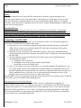
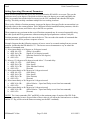
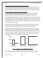
Serial Connection Note
The IPS-AMP uses one line for both the serial input and output. If the serial output line of your
microprocessor cannot be tri-stated under software control (high-impedance output state) between
command transmissions, it will require additional circuitry to accomplish this. A simple circuit is shown
below.
+V
5k
CPU Input
CPU Output
To IPS-AMP
Serial Input
2N4403
or equiv.
Gnd
Fig. 1 - Serial I/O Connection Schematic
Using the PC Interface Software
As noted previously, the IPS-AMP serial interface was designed to "converse" with a computer, not a
human being. Therefore, the interface is not robust. While input parameters need to be within certain
ranges, they are not range-checked. There are no text correction characters such as backspace or delete.
The commands are all short, 3-character mnemonics. And there is no on-line help available directly
from the IPS-AMP.
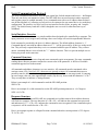
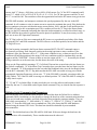
To make the device easier to test and program, a special VB Application (Orion) has been developed by
GAA Custom Electronics. (See Fig. 2 – IDE Screen Shot) The software allows control of configuration
of all IPS capabilities and includes a scripting capability to simulate several computer commands issued
IPSManualV3.0.doc
Page 8 of 48
01/19/2012
Draft
GAA Custom Electronics
sequentially. Additionally a USB interface module is available to provide the hardware connections
between the PC and your IPS. Contact GAA Custom Electronics to obtain more information.
Fig. 2 – IDE Screen Shot
IPSManualV3.0.doc
Page 9 of 48
01/19/2012
Draft
GAA Custom Electronics
Programming the Basic Device Parameters
To begin using the IPS-AMP there are several basic parameters that must be defined. Next the operating
parameters must be set. And finally the movement commands must be given. Define commands start
with the letter "D". They are specific to the device and the user application, set once, or very rarely, and
left alone. They generally relate to the communication interface, the internal device configuration and
external physical device application.
Once those parameters are defined the IPS-AMP is ready for the operation parameters to be set. Set
commands begin with the letter "S". They are also used in Tables, which will be discussed later. Finally
the Movement command is given. Several IPS-AMPs can be given Set commands, and then one
Movement command can begin execution of all devices simultaneously. This feature is useful to
coordinate the actions of multiple devices working in unison.
Defining the Device Address
The IPS-AMP was designed to employ a multi-drop interface – i.e. several devices can all use the same
CPU data I/O pin. To route specific commands to the proper devices each IPS-AMP on the same I/O pin
must have a unique address. The device address is a single ASCII character. Any character can be used
with the exception of " * " which is reserved to indicate that a command applies to all devices on that
particular I/O signal line.
The default address that is programmed at the factory is "1". If each IPS-AMP is on its own unique I/O
line, it is possible to leave this parameter set to "1". However, it is recommended that each address
character in some way reflect its purpose in the application. For instance, if two IPS-AMPs are being
used in a pan & tilt mechanism, one could have the address of "P" and the other "T". Since the addresses
are case sensitive, if the application has two pan & tilt mechanisms on the same I/O pin, the second
could use "p" and "t". This will help make the control software more user-friendly, at least as userfriendly as one-character addresses can be.
Because each address is unique, it must be programmed individually before multiple devices are
connected together. The PC software available from GAA Custom Electronics is ideal for performing
this function. If this is not available, PC applications are available on the Internet such as Hyperterm.
They may be used instead, but it must be remembered that the IPS-AMP interface is not very forgiving
regarding typographical errors, so care must be exercised when using these programs.
NOTE:* The IPS-AMP uses different electrical voltages than the RS-232 interface of your PC. It is
VERY important that some hardware circuitry be used to convert the PC signal levels to those used by
the IPS-AMP. Connecting the device directly to the I/O pins of a PC serial connector will damage the
IPS-AMP and void your warranty.
When using Hyperterm, or some other software to Define the address of the IPS-AMP to a lower-case
"a", send the following command:
1DDA a<CR>
The IPS-AMP will respond with a "<CR><LF>" acknowledging your command. From that time on, this
IPS-AMP will respond only to commands that begin with the letter "a" (or " * " to indicate the command
is for ALL devices on that serial line). Be sure to save the new device address to EEPROM. (See the
ESV command.)
IPSManualV3.0.doc
Page 10 of 48
01/19/2012
Draft
GAA Custom Electronics
Defining the Mechanical Parameters
The IPS-AMP is a multi-purpose device capable of many functions. Each user application is very likely
going to be unique. One way in which an application can be unique is in the range of motion required
for operation. Some applications will require the full range of motion of the IPS-AMP. Some will
require substantially less. In fact some mechanical systems might be damaged if the full range of motion
is used. Additionally, the point that is considered "zero" may not necessarily be in the middle of the
range of motion. The IPS-AMP permits any of these situations and makes it easy to tailor each system.
There are four parameters that must be defined to configure the mechanical system constraints. They are
the Zero Position, Clockwise Rotation Limit, Counter-Clockwise Rotation Limit, and the Direction of
Rotation that will be referred to as "Positive". (If the factory defaults perform in the user system as
desired, there is no need to change these parameters.)
There is an internal potentiometer mounted to the output shaft of the IPS that senses its rotational
position. The internal microcontroller reads that position constantly and converts that reading to units of
degrees to aid the user. The first task is to define the rotational position that the system will refer to as
0.0 degrees. This should be defined once and left alone. All subsequent positions will be referenced
from this position.
To accomplish this connect the IPS to power and establish communication with it. Then define the
Motor Current to 0% (see the DMC command), which effectively turns the motor off. Now the IPS can
be moved to any position in its range of motion manually. Move it to the position that will be considered
zero and enter the Define Zero Position command (DZR) with no parameter. Without a parameter the
device will assume the current position is the one meant. The basis for all further absolute position
commands is now defined.
Now rotate the IPS clockwise to the furthest position you want it to move during operation and enter the
Define Limit Position Clockwise command (DLC). Follow this with the counter-clockwise position and
the Define Limit Position Counter-Clockwise command (DLK).
Next establish which direction the IPS is to consider the Positive direction. If clockwise rotations are
positive in the system, such as compass headings, send the Define Device Direction command (DDD)
with CWP (clockwise positive) as the parameter. If counter-clockwise rotations will be considered
positive, such as in systems using trigonometric, unit-circle angles, then send the Define Device
Direction command with CWN (clockwise negative) as the parameter. (Clockwise Positive is the factory
default.)
Once these four parameters have been set, re-establish the motor current with the DMC command and
test the mechanical limits. Readjust them as required using this method. Once the parameters are
properly tuned, save them in non-volatile memory (see the ESV command).
NOTE:* It is not good practice to set either of the rotational limits of the IPS fully against its internal
mechanical stop. It's better to back it off the stop slightly. If the IPS hits a mechanical stop during
operation the motor will stall. While it's unlikely this will damage the device, the motor will draw the
full current possible. This could overload the electronic system, or cause excessive electrical noise.
Minimally it will shorten battery life unnecessarily.
IPSManualV3.0.doc
Page 11 of 48
01/19/2012
Draft
GAA Custom Electronics
Setting Operating (Movement) Parameters
There are three parameters that specify the movements that the IPS-AMP is to execute. They are the
position to move to (in degrees), the speed at which to move (in degrees per second) and finally the
delay (in seconds) between the order to execute (see the GO! command) and when the IPS begins
moving. This delay can help coordinate multiple devices working in unison.
There is also a Relative Position parameter (expressed in degrees) that specifies the movement that is to
be made relative to the current position. This is different from the standard Position parameter, which is
defined in absolute terms, and relative only to the IPS zero position.
These parameters are persistent in that several Position commands may be executed sequentially using
the same Speed and Delay parameters without resetting the Speed parameter each time. Only the
Position parameter would need to be sent to the device. This can reduce the number of commands that
must be sent to the IPS to perform a sequence of move.
Example: Suppose that the following sequence of moves was to be executed starting from any current
position. Assume that the IPS address is "a". The last two moves demonstrate a way to reduce the
number of commands sent.
1) Move immediately to 0.0 degrees at 10 degrees/second.
a. aSDL 0.0<CR>
(Delay 0.0 seconds)
b. aSSP 10.0<CR>
(Speed of 10.0 degrees/second)
c. aSPS 0.0<CR>
(Absolute Position of 0.0 degrees)
d. aGO!<CR>
(Execute)
2) Move to 15.0 degrees at 20 degrees/second after a 3.2 second delay.
a. aSDL 3.2<CR>
(New Delay)
b. aSSP 20.0<CR>
(New Speed)
c. aSPS 15.0<CR>
(New Absolute Position)
d. aGO!<CR>
(Execute)
3) Move immediately to 20.0 degrees at 10 degrees/second.
a. aSDL 0.0<CR>
(New Delay)
b. aSSP 10.0<CR>
(New Speed)
c. aSPS 20.0<CR>
(New Position)
d. aGO!<CR>
(Execute)
4) Move immediately to 30.0 degrees at 10 degrees/second.
a. aSRP 10.0<CR>
(Move Relative – Speed and Delay are set from last command)
b. aGO!<CR>
(Execute)
5) Move immediately to 40.0 degrees at 10 degrees/second.
a. aSRP 10.0<CR>
(Move Relative – Speed and Delay are set from last command)
b. aGO!<CR>
(Execute)
NOTE:* The Limit commands (DLC and DLK) set the maximum range of motion of the IPS. If the
device is commanded to move beyond either of these values it will stop at the limit and move no farther,
and the "E" flag will be set in the Status text string (see the RST command).
IPSManualV3.0.doc
Page 12 of 48
01/19/2012
Draft
GAA Custom Electronics
Initiating and Halting Movement
There are two commands that directly control the movement of the IPS. They are "GO!" and "HT!",
which stand for "Go Now" and "Halt Now". The GO! command, as shown in the example above, is used
to initiate movements that have been setup by sending previous Operational Parameters. It is also used
to initiate the execution of a particular table, which also would have been setup using the various Table
commands as explained later in this manual.
Another function of the GO! command is to coordinate the movement of several IPS-AMPs. Suppose a
system contains three devices with the addresses of "a", "b" and "c" and all of them are on the same I/O
line. Each of their movements, while being different, must all begin at the same time. Here is how that
might be programmed:
1) Set all devices on this line to a 1.0 second delay.
a. *SDL 1.0<CR>
(" * " indicates command is for all listening devices)
2) Set Speed and Position for a.
a. aSSP 10.0<CR>
(Set device "a" to move at 10.0 degrees/second)
b. aSPS 10.0<CR>
(Set device "a" to move to 10.0 degrees)
3) Set Speed and Position for b.
a. bSSP 20.0<CR>
(Set device "b" to move at 20.0 degrees/second)
b. bSPS 20.0<CR>
(Set device "b" to move to 20.0 degrees)
4) Set Speed and Position for c.
a. cSSP 30.0<CR>
(Set device "c" to move at 30.0 degrees/second)
b. cSPS 30.0<CR>
(Set device "c" to move to 30.0 degrees)
5) All start at the same time.
a. *GO!<CR>
(Execute – all 3 listening devices a, b and c)
Saving and Retrieving Parameters from Non-Volatile Memory
All parameters that control the operation of the IPS are manipulated and managed from the CPU's
random access memory (RAM). The advantage of RAM is that it is fast to use and easy to modify. The
disadvantage is that it does not maintain its state when power is removed. It would be impractical to
require the user to reprogram the IPS-AMP every time it is to be utilized. To prevent this, all parameters
are saved in onboard non-volatile memory, called EEPROM.
When power is applied to the IPS-AMP one of the first things it does is to retrieve all parameters from
EEPROM memory and place a copy of them into RAM thus restoring the "state" of the device to what it
was previously. This is important because it allows users to customize the operation of each IPS in a
system.
Here is another way to think about this. When making revisions on a document, it's better to make a
copy and do editing on that, thereby keeping the original untouched and safe. Once the revisions are
complete, the original document may be replaced with the new one. Even then, it is often a good idea to
keep a copy of the original available in case one day it is needed for reference purposes. Directly
modifying parameters stored in EEPROM would be like working on the original document. The IPSAMP does not require this.
There are three commands available for working with non-volatile memory (EEPROM). They are ELD,
ESV and ERD. ELD is the Load RAM from EEPROM command. It is used to return all parameters of
IPSManualV3.0.doc
Page 13 of 48
01/19/2012
Draft
GAA Custom Electronics
the IPS-AMP to the last, previously saved state. This is essentially what the device does every time
power is applied but before it begins operating.
The converse of the ELD command is ESV. ESV saves (in EEPROM) a copy of the current parameters
from RAM. This allows the user to make modifications to various parameters, test them to ensure they
operate as desired, and then save them in non-volatile memory so that they are available whenever the
device powers up.
The third EEPROM command is the ERD command. It returns all parameters to the factory defaults. It
will probably only be used if sufficient experimentation is done with many parameters such that it would
be easier to return the IPS-AMP to a known state with a single command, rather than having to change
every parameter individually.
It should be noted that choosing to use the EEPROM commands should be done very carefully. There
are several side effects of these commands that might not be immediately obvious. First of all, writing to
EEPROM, due to the technology involved, takes time. While performing this task the IPS-AMP is
unable to do any movements.
Also, depending upon the values of some of the restored parameters, the device may begin moving
immediately. So the user needs to keep clear of all mechanisms involved. Another potential side effect is
that the communication parameters also return to their default values. This includes the baud rate, but
more importantly, the device address. If the IPS-AMP in question had been assigned a new device
address, it will now be back to the factory default of "1", and it will not respond to commands at its
previous address.
The bottom line: act carefully and thoughtfully when using the EEPROM commands. They can have
unforeseen side effects that may cost considerable time and effort to rectify.
IPSManualV3.0.doc
Page 14 of 48
01/19/2012
Draft
GAA Custom Electronics
Programming More-Complex Device Parameters
The next class of commands will largely be used by those who are more familiar with the IPS and wish
to experiment with more sophisticated control. They are the various status reporting commands, the
motor current controls and those that control the serial interface. There are also a group of commands
that manage the IPS if there is a loss of communication, either serial or if using the R/C pulse interface.
Using the "Report" Commands to Get Device Status
There are four reporting commands available in the IPS. They are Report Version (RVR), Report
Position (RPS), Report Current (RCU) and Report Status (RST). With careful consideration the
reporting commands can be used to get information on the operating environment of the IPS.
The Report Version command (RVR) will return a text string that shows the current version of firmware
that is programmed into the IPS. The manual also has a version number. Make sure they match. Having
the correct documentation is necessary when using or debugging the device. Also, the factory can update
the IPS-AMP firmware. Check the GAA Custom Electronics web site to see what versions of firmware
exist for the IPS-AMP, and what improvements each version makes available. Details on returning your
device for updating are on the web site.
The Report Position command (RPS) will return the current position of the IPS in degrees based upon
the zero position that was set by the DZR command. If the device is moving (see the Report Status
command), the returned value will reflect the actual position at the time of command entry.
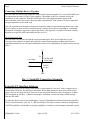
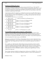
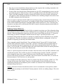
The Report Current command (RCU) can be used to determine the load that is on the IPS. The current
applied to the motor is pulse-width modulated (PWM), so the average current applied is a function of
two things: the peak current of the applied voltage and the duty-cycle of the current. The figure below
helps illustrate this. It should be noted that all values of current discussed for this device are in terms of
the stall current of the motor (full current applied with no motor movement), which is the maximum
current the motor will draw. In the IPS-AMP this is referred to as 100%. All currents reported are in
percent of stall current, so the numbers will always be from 1 to 100.
100%
A
B
C
50%
0%
30% Duty Cycle
70% Duty Cycle
100% Duty Cycle
Fig. 2 – Motor Current PWM Waveforms
Figure 2 shows just three out of thousands of possible motor current PWM waveforms. The first, "A",
shows a 30% duty-cycle at 50% of stall (full) current. "B" shows a 70% duty-cycle at 100% of stall
IPSManualV3.0.doc
Page 15 of 48
01/19/2012
Draft
GAA Custom Electronics
current. And "C" shows a 100% duty-cycle at 100% of full current. For "A" the RCU command would
report "15", which is 30% of 50% (0.30 X 0.50 = 0.15 = 15%). For "B" the response would be 70, and
for "C" it would be 100. These numbers reflect the approximate load on the IPS motor at any given time.
The IPS-AMP monitors, and attempts to maintain, the speed programmed by the user in the SSP
command. It will continue to raise its motor current as required to maintain that speed. If the load on the
device continues to increase such that the motor current reaches 100%, and that is still insufficient, the
IPS-AMP will not be able to maintain speed. This condition will set the "E" flag in the Report Status
string (see the RST command) indicating that either the load momentarily exceeded its normal range, or
the IPS-AMP has been asked to perform beyond its physical capabilities. It may be necessary to scale
back one or more IPS Operation Parameters.
The "E" flag is also set if the user commands the IPS to move to a position beyond either of the limits
set using the DLC and DLK commands. The IPS will move to the limit position, but no farther and the
"E" flag will be set.
The final reporting command is the Report Status command (RST). The RST command returns a
six-character text string. Each character position in the string represents a status condition. If the
condition is false, the character will be a "-". If the status condition is true, a character specific to that
condition will hold that position in the string. If all error conditions could be simultaneously true the
output would be "FOETMW". If none of them are true the output will be "------". In actuality the M and
W flags cannot be set at the same time, but this shows the order of the string.
These are the Flags and their meanings: "F" if a Failsafe Timeout has occurred since the last Status (see
the Failsafe commands). "O" if the Motor Trip Current has been exceeded since the last Status (see the
DMC command). "E" if the position error has exceeded the Deadband value since the last Report Status
(see the RCU command). The "E" flag indicates that the IPS-AMP was unable to keep pace with the
programmed Operation Parameters at least once. "T" if the IPS-AMP is currently executing a table (see
Using Tables). "M" if the IPS-AMP is moving to a defined position. "W" if the IPS-AMP is waiting for
a delay time to expire.
"F", "O" and "E" are latched flags. In other words they are set in the software and remain set until
cleared by the user. To clear them send a Report Status command. They are cleared after the response is
sent.
Defining Serial Communication Parameters
Thus far the only serial communication parameter discussed has been the Define Device Address
command (DDA). In addition it is also possible to change the baud rate of the communication interface.
There are six baud rates available, and each of them has been assigned a parameter number. They are
2400 which corresponds to "1", 4800 which is "2", 9600 is "3", 19200 is "4", 57600 is "5" and 100k
baud is "6". Note that 100k baud is not a standard rate. This is the fastest the IPS-AMP hardware
allowed using the internal CPU clock. This baud rate should be obtainable by most standard
microcontrollers.
NOTE:* The default baud rate of the IPS-AMP is 9600 baud. If the user changes the baud rate, the
command takes effect immediately. These considerations must be observed.
IPSManualV3.0.doc
Page 16 of 48
01/19/2012
Draft
•
•
•
GAA Custom Electronics
First, the user must immediately change baud rate on the computer that is sending commands to the
IPS-AMP to continue communicating with the device.
Second, if this is the desired future communication rate, the ESV command must be sent to save the
new baud rate in non-volatile memory so that it is available whenever the IPS-AMP is powered-up.
Third, if the ERD command is issued to return the IPS-AMP to the factory defaults, the baud rate
also returns to 9600. If the desired baud rate is different, the controlling computer must send at least
the DBR command at the 9600 baud rate.
If the user wants to implement the IPS-AMP in an environment where communication from the device
to the controlling computer is not desired, it is possible to disable all data responses from the device. To
do this send the Define Data Response command (DDR) with the parameter of "NO". From that point
forward no serial data will be sent from the IPS-AMP. It must be remembered that this also disables all
of the reporting functions.
Defining Failsafe Behavior
Unlike standard R/C servos, the IPS has the ability to maintain its position even if the information being
sent to the device ceases. It does not matter whether the device is using the R/C pulse mode or the serial
interface. When the information stream stops, the IPS enters Failsafe Mode and sets the "F" flag in the
status string (see the RST command). Often this means moving to a specified position to await
resumption of the position data. However, moving to a position may not be desirable in every possible
user application. Therefore, the behavior of the device in Failsafe Mode is configurable. In fact, it is
possible to completely prevent entry into Failsafe Mode.
Three commands control Failsafe Mode. They are Define Failsafe Timeout (DFT), Define Failsafe
Position (DFP) and Define Failsafe Current (DFC). The DFT command sets the acceptable length of
time in seconds that the interface signal pin will sit idle before entering Failsafe Mode. The range is
from 0.1 to 99.9 seconds. To completely disable entry into Failsafe Mode, define the timeout parameter
to 0. This tells the firmware to never enter failsafe mode.
If there is a preferred position for the IPS to assume if the data stream ceases, the DFP command is used
to define that position. This could be anywhere in its defined range of motion. The DFC command is
used to change the motor drive current if the device enters Failsafe Mode. Again this number is in
percent of full current (see the RCU command). If the usual current is lower than 100%, it could be set
to the maximum to "lock" the device in a new position.
If it's desirable for the IPS to effectively "float" its position if the data stream stops, set DFC to 0. This
will turn off the motor if the Failsafe Timeout is exceeded and the device will back-driven to an
equilibrium position by the mechanical system to which it is connected. This could be the internal
mechanical stop of the device.
NOTE:* If the desired action when the data stream ceases is to maintain the current position, disable
Failsafe Mode by entering 0 as the Failsafe Timeout parameter. In this case nothing changes. This is the
factory default.
IPSManualV3.0.doc
Page 17 of 48
01/19/2012
Draft
GAA Custom Electronics
Defining the Motor-Current Parameters
The IPS continually monitors the motor drive current for both control and status reasons. The value of
the current is available using the RCU command. Additionally it is possible to set some behaviors if the
motor drive current exceeds certain user-defined parameters. The motor current commands are Define
Motor Current (DMC), Define Trip Current (DTC) and Define Reduced Current (DRC).
The DMC command is used to set the maximum current value that the IPS will use to execute the
movements requested by the user. This number is in percent of motor stall current, so the range is 0 to
100. (See the RCU command.) Higher numbers yield the possibility of greater performance. Lower
numbers will yield system compliance, but if the number is too low the system may be unable to satisfy
the user specified dynamics. Again, if this occurs, the "E" flag will be set and latched in the Status text
string. Unless there are reasons to do otherwise, leaving this value at the factory default of 100 is
suggested for normal operation.
NOTE*: Defining the motor current to 0 is the way to temporarily allow the IPS to be adjusted manually
for setting the various mechanical limits set by the DLC, DLK and DZR commands.
Under certain conditions it may be desirable to specify a maximum motor current such that exceeding
this value would be detected, reported and change the behavior of the IPS. Defining a Trip Current will
accomplish this. The Trip Current is also specified in percent of stall current (0 to 100). Exceeding the
Trip Current causes two actions. First the "O" flag is set in the Status text string, and it will remain
latched until the string is read via the RST command.
The other effect is that the value defined by the Define Reduced Current command (DRC) will be
moved into the Define Motor Current parameter. Normally this value would be lower than the normal
motor current, assuming that the Trip Current is not to be exceeded. However, if the user desired, the
trip condition could actually be used to set a higher current, such as to detect and overcome a
circumstance that required more mechanical power.
NOTE:* The Reduced Current value will remain in effect until the user sets it back to its "normal" value
using the DMC command.
IPSManualV3.0.doc
Page 18 of 48
01/19/2012
Draft
GAA Custom Electronics
Using Tables
There are often reasons to execute a particular series of known moves multiple times. It would be
advantageous to accomplish this with one simple command rather than to deal with the overhead of
continuing to input and execute the sequence manually. The IPS-AMP provides this capability through
its Tables.
A Table is simply a pre-programmed sequence of movements that can be entered once and then
executed with two commands. There are 10 tables in the IPS-AMP. Each has room for 6 entries. One
entry consists of a delay (SDL command), a speed (SSP command) and a position (SPS command).
Tables may be executed once, multiple times, or continuously. The RST command can be used to
determine the state of table execution, i.e. whether the device is actually executing a table, and within
that table, whether or not it is waiting for a delay to expire or currently moving.
There are five commands used to create, maintain and execute tables. They are: the Table Reset
command (TRS), the Table Step Enter command (TSE), the Table Report Entries command (TRP), the
Table Mode command (TMD) and the Table Ready for GO! command (TRD).
The Table Reset command is the safest way to begin creating a table. It clears all the table entries in the
specified table and sets the number of entries for that table to 0. The parameter sent is the table number
and a parameter is required for this command, unlike many others.
The Table Step Enter command is used to build the table. In preparation to enter each step, a delay,
speed and position must all be set using the SDL, SSP and SPS commands. When all three parameters
are set, send the TSE command with a parameter of the table number. This will enter those three values
as the next available step in the table. Once again, a parameter of the table number is required for this
command.
When all desired steps have been entered, the table entries can be verified using the Table Report Entries
command, again with a required parameter of the table number. The output of the TRP command is one
line with the number of valid steps in the table. Following that line is one line for each table entry. An
example output is shown below.
2
00.0 00.0 –090.6
01.0 05.0 025.0
This example shows 2 steps entered. The first is a delay of 00.0 seconds, a speed of 00.0 (as fast as the
IPS can move) to a position of –90.6 degrees. The second entry follows the same format.
Once the table has been defined, the Table Mode command tells the IPS how many iterations it is to
execute with the one command. The valid number is from 1 to 250. If 0 is entered, the table will execute
forever. If this command is sent during an execution sequence without a parameter, it will return the
number of remaining iterations.
The final Table command is TRD, which is always sent with a parameter of the table number. It sets a
flag indicating that the specified table is to be executed when the next GO! command is sent. Again this
allows the coordination of multiple IPSs acting in unison. If this command is sent with a parameter of 0
it will cancel any pending TRD command to clear a previously set Table Mode flag.
IPSManualV3.0.doc
Page 19 of 48
01/19/2012
Draft
GAA Custom Electronics
Operating Modes
The IPS-AMP has four operating modes, any of which can be selected using the Define Operating Mode
command (DOM). The factory default mode is Mode "1" – Pulse Mode. In Mode "1" the device acts just
like a digital R/C servo. Mode "2" is the serial mode, which gives the user access to all the device
parameters and more sophisticated operation. Mode "3" uses the pulse interface to select a table for
execution. And Mode "4" is an automatic, continuous table execution mode.
If the IPS is programmed to be in pulse mode, the serial mode can get the attention of the internal CPU
by holding the input signal wire above 4 Volts for the first two seconds after the IPS-AMP powers up.
The IPS-AMP senses the voltage on the signal wire for the first 2 seconds after power-up. If the
Operating Mode is set to "1" or "3", and the signal line is at 0 Volts, it will operate in the R/C-pulse
mode. If the signal line is at +4V or more, the serial interface will be active, overriding Mode "1" or "3"
if they were programmed by the user. If the signal line is not stable at the two-second mark, or the signal
line is noisy, the IPS-AMP may not choose the correct interface for your intended application.
In Mode "1" and Mode "3", the IPS-AMP is capable of interfacing with an R/C receiver or computer
that is using the 1-2 millisecond R/C-pulse interface, or a computer using a 0-5V serial interface. The
pulses must be "positive-pulses" meaning that the normal state of the signal line is 0 Volts. There must
be at least 10 milliseconds of 0 Volts between pulses.
In Mode "1" the high-time of the input pulse is measured and the position is calculated based on the
pulse length. 1-millisecond (ms) pulses will position the IPS at one end of its travel and 2ms pulses will
move it to the other end. A 1.5ms pulse will place it in the center. The exact pulse length required to
move to the center position is programmable along with a gain value to define the movement executed
for the range of the input pulses. The Define Pulse Gain (DPG) and Define Zero Pulse Length (DPZ)
commands accomplish this. However, these are advanced commands and should be used cautiously.
In Mode "3" the IPS-AMP will select one of two sequence tables to execute. If the pulse on the input
line is 1ms in length, Table 1 will execute once. If the input pulse is 2ms in length, Table 2 will execute
once.
Mode "4" causes Table 1 to begin executing shortly after power-up and to continue executing as long as
power is applied. All the capabilities of Mode "2", serial mode, are available in Mode "4".
IPSManualV3.0.doc
Page 20 of 48
01/19/2012
Draft
GAA Custom Electronics
Changing the Device Calibration
NOTE:* The following commands are intended only for advanced users because they have the ability to
render the device partially or completely non-functional. If these parameters are changed, be prepared to
either set them to their factory default values individually, or to use the ERD command to restore all
parameters. Also exercise caution when using the ERD command due to the possibility of unforeseen
side effects.
Tuning the R/C Pulse Parameters
There are two commands that change the operation of the IPS when using the R/C pulse interface for
Mode "1". They are the Define Zero Pulse Length command (DPZ) and the Define Pulse Gain command
(DPG). The DPZ command is used to set the center of the range of motion. The DPG command is used
to increase or decrease the total range of motion.
The pulse length of a normal "zero position" pulse is 1.5ms, or 1500 microseconds (µs). Because R/C
transmitter may not precisely hit 1500µs for the center position, the IPS-AMP is capable of using a
different pulse length to indicate center. The range is from 1000µs to 2000µs.
The user can change the amount that the IPS moves for a given change in pulse length using the DPG
command. The higher this number is, the larger the swing will be for a given change in pulse length.
There is only one gain for both directions of swing, so it affects both directions equally. To move the
movement center position in only one direction away from the signal center position the user will need
to modify this parameter in conjunction with the DLC and DLK commands. The pulse gain will have to
be high enough to reach farthest position in the direction of swing with the greatest amplitude, and the
DLC or DLK commands used to stop the motion on the short side before it hits the internal, mechanical
stop in the IPS.
Tuning the Motor Control-Loop Parameters
There are three parameters that affect the motor movement in the IPS when using serial mode. They are
the Define Dead Band command (DDB), the Define Control-Loop Gain command (DCG) and the
Define Derivative Gain command (DDG).
The Deadband sets the "error" value that the IPS-AMP will tolerate between the actual and desired arm
position before taking action to bring the device back into command compliance. Two or three will
usually be sufficient, but tighter accuracy may be obtained by making this number as small as 0. The
disadvantage of low numbers is that the IPS will appear to hum or chatter as it skips back and forth over
the programmed position to maintain no, or very low, error numbers. This increases the current load
placed on the supply to the IPS, potentially shortening battery life if batteries are being used.
The DCG command………
The DDG command………
IPSManualV3.0.doc
Page 21 of 48
01/19/2012
Draft
GAA Custom Electronics
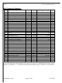
IPS Command Summary
Abbr.
Name
Command
Type
Parameter
Guidelines
Valid Range of Parameter
(Range validation is not done)
Factory
Default
DBR
DDA
DDR
DDD
DLC
DLK
DZR
DMC
DRC
DTC
DOM
SDL
SPS
SRP
SSP
GO!
HT!
DFC
DFP
DFT
ELD
ERD
ESV
RCU
RPS
RST
RVR
TMD
TRD
TRP
TRS
TSE
DCG
DDB
DDG
DPG
DPZ
Define Baud Rate
Define Device Address
Define Data Response
Define Device Direction
Define Limit Position Clockwise
Define Limit Position Counter-Clockwise
Define Zero Position
Define Motor Current
Define Reduced Motor Current
Define Motor Trip Current
Define Operating Mode
Set Delay
Set Position
Set Relative Position
Set Speed
Go Now
Halt Now
Define Failsafe Current
Define Failsafe Position
Define Failsafe Time Out
Load Parameters from EEPROM
Restore Factory Defaults to EEPROM
Save Parameters to EEPROM
Report Current
Report Position
Report Status
Report Version
Table Mode
Table Ready for GO!
Table Report Entries
Table Reset
Table Step Enter
Define Control-Loop Gain
Define Dead Band
Define Derivative Gain
Define Pulse Gain
Define Zero Pulse Length
Comm.
Comm.
Comm.
Application
Application
Application
Application
Application
Application
Application
Application
Operation
Operation
Operation
Operation
Movement
Movement
Failsafe
Failsafe
Failsafe
EEPROM
EEPROM
EEPROM
Report
Report
Report
Report
Table
Table
Table
Table
Table
Calibration
Calibration
Calibration
Calibration
Calibration
Required
Required
Optional
Optional
Special
Special
Special
Optional
Optional
Optional
Optional
Optional
Optional
Optional
Optional
None
None
Optional
Optional
Optional
None
None
None
None
None
None
None
Optional
Required
Required
Required
Required
Optional
Optional
Optional
Optional
Optional
1, 2, 3, 4, 5, 6
Any ASCII character except *
YES, NO
CWP, CWN
-199.9 to 199.9 and manual
-199.9 to 199.9 and manual
-199.9 to 199.9 and manual
0 to 100
0 to 100
0 to 100
1, 2, 3, 4
0.0 to 99.9
-199.9 to 199.9
-199.9 to 199.9
0.1 to 500.9 and 0
N/A
N/A
0 to 100
-199.9 to 199.9
0.1 to 99.9 and 0
N/A
N/A
N/A
0 to 100
-199.9 to 199.9
3
1
YES
CWP
90.0
-90.0
0.0
100
100
100
1
0.0
0.0
0.0
0
N/A
N/A
0
0.0
0
N/A
N/A
N/A
N/A
N/A
N/A
2.0
1
N/A
N/A
N/A
N/A
100
3
-150
-150
1500
F or - O or - E or - T or - M or - W or -
Current Software Version
1 to 250 and 0
1 to 10 and 0
1 to 10
1 to 10
1 to 10
-999 to 999
0 to 100
-999 to 999
-999 to 999
1000 to 2000
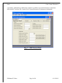
On the following pages each command will be discussed in detail. All commands will be shown with the
default servo address of "1". X's indicates an input argument and its range is defined for each command.
IPSManualV3.0.doc
Page 22 of 48
01/19/2012
Draft
GAA Custom Electronics
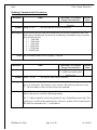
Defining Communication Parameters
Mnemonic
Name
Valid Range of Parameter
(Range is not checked!)
DBR
Define Baud Rate
1, 2, 3, 4, 5, 6
Required
Format: 1DBR X<CR>
Sets the baud rate for the serial interface.
Default
Value
3
Description: In serial mode, the IPS-AMP can communicate at several pre-programmed rates from
2400 baud to 100,000 baud. The baud rate is defined by selecting the proper parameter
from the following list:
1 = 2400 baud
2 = 4800 baud
3 = 9600 baud
4 = 19200 baud
5 = 57600 baud
6 = 100000 baud
Notes: The serial data format is 8-bit, No parity, 1 Stop bit.
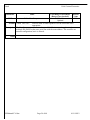
Mnemonic
Name
Valid Range of Parameter
(Range is not checked!)
DDA
Define Device Address
Any ASCII Character
* = All devices on this serial
interface line
Format: 1DDA X<CR>
Sets the IPS-AMP address character.
Default
Value
1
Description: This command defines the ASCII character that will be used for the address of this
device in serial mode. The character is case sensitive and can be any character except
"*". The new address will be in effect for the next command.
Notes: Since all devices can share the same serial interface, it is important to program the
address character for each IPS-AMP independently.
The "*" address cannot be used as an argument for any command that returns data. This
would cause a conflict on the multi-drop bus. Therefore, no data will be returned by the
IPS-AMP on commands with "*" as the address.
IPSManualV3.0.doc
Page 23 of 48
01/19/2012
Draft
GAA Custom Electronics
Mnemonic
Name
Valid Range of Parameter
Default
(Range is not checked!)
Value
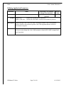
DDR
Define Data Response
YES, NO
YES
Optional
Format: 1DDR YES<CR>
Sets IPS-AMP to send responses over the serial link when
appropriate.
Description: The Data Response parameter can be set to NO if for instance the application has
multiple IPS-AMPs on the same serial line with the same address. This would be an
unusual configuration, but it is allowed.
Notes:
IPSManualV3.0.doc
Page 24 of 48
01/19/2012
Draft
GAA Custom Electronics
Defining Application Parameters
Mnemonic
Name
Valid Range of Parameter
Default
(Range is not checked!)
Value
DDD
Define Device Direction
CWP, CWN
CWP
Optional
Format: 1DDD<CR>
Returns the current Device Direction.
1DDD CWP<CR> Defines the IPS-AMP’s clockwise movements as positive.
Description: Defines the sign value of the IPS-AMP’s clockwise rotation. The CWP argument
defines clockwise movements as positive, the CWN argument defines clockwise
movements as negative.
Notes: This command takes effect immediately. It does NOT wait for the next GO! command.
It is best to only change the value of this parameter when the IPS-AMP is stopped and
at the 0 position.
IPSManualV3.0.doc
Page 25 of 48
01/19/2012
Draft
GAA Custom Electronics
Mnemonic
Name
Valid Range of Parameter
Default
(Range is not checked!)
Value
DZR
Define Zero Position
-199.9 to 199.9
0.0
Special
Format: 1DZR<CR>
Defines the current physical position of the IPS-AMP as the Zero
Position.
1DZR XX.X<CR> Defines the IPS-AMP Zero Position in degrees.
Description: This command defines the reference physical position the IPS-AMP for all future
position commands. Always define the Zero Position before defining either of the other
physical limits of the device using the DLC and DLK commands.
The zero position for the IPS-AMP can be set using two methods. It can be physically
set by turning the IPS-AMP motor current to 0 (DMC command), then physically
turning the IPS-AMP to the position that will be referred to as the zero reference and
then entering the DZR command with no argument.
The second method is to set the desired physical zero-position of the IPS-AMP in the
system, and then obtain the position value using the RPS command (Report Position)
and then entering that number as the argument of the DZR command.
Once the new Zero Position has been entered, all future references to position including
Report Position commands (RPS) and Set Position commands (SPS) will return values
based on this new zero.
Notes: This value should be set once and left alone. It provides the basis for the Limit
commands (DLC and DLK) and all movement.
IPSManualV3.0.doc
Page 26 of 48
01/19/2012
Draft
GAA Custom Electronics
Mnemonic
Name
Valid Range of Parameter
Default
(Range is not checked!)
Value
DLC
Define Limit Position Clockwise
-199.9 to 199.9
90.0
Special
Format: 1DLC<CR>
Sets the Clockwise Limit Position to the current physical
position of the IPS-AMP.
1DLC XX.X<CR> Defines the Clockwise Limit Position in degrees.
Description: This command defines the maximum physical position the IPS-AMP will attempt to
achieve in the clockwise direction. If a command or position pulse is given that exceeds
this range, the IPS-AMP will stop at this limit value. This prevents the IPS-AMP from
stalling against its physical limit, or a physical limit in the application mechanism,
which might damage the unit.
Always define the Zero Position first by using the DZR command.
This limit can be physically set by: Turning the IPS-AMP motor current to 0 (DMC
command), then turning the IPS-AMP clockwise to the limit you desire. At that point do
one of two things: Either enter the DLC command with no argument, or obtain the
current position by using the RPS command (Report Position) and then enter that
number as the argument of the DLC command.
Notes:
IPSManualV3.0.doc
Page 27 of 48
01/19/2012
Draft
GAA Custom Electronics
Mnemonic
Name
Valid Range of Parameter
Default
(Range is not checked!)
Value
DLK
Define Limit Position Counter-Clockwise
-199.9 to 199.9
-90.0
Special
Format: 1DLK<CR>
Sets the Counter-Clockwise Limit Position to the current physical
position of the IPS-AMP.
1DLK XX.X<CR> Defines the Counter-Clockwise Limit Position in degrees.
Description: This command defines the maximum physical position the IPS-AMP will attempt to
achieve in the counter-clockwise direction. If a command or position pulse is given that
exceeds this range, the IPS-AMP will stop at this limit value. This prevents the
IPS-AMP from stalling against its physical limit, or a physical limit in the application
mechanism, which might damage the unit.
Always define the Zero Position first by using the DZR command.
This limit can be physically set by: Turning the IPS-AMP motor current to 0 (DMC
command), then turning the IPS-AMP counter-clockwise to the limit you desire. At that
point do one of two things: Either enter the DLK command with no argument, or obtain
the current position by using the RPS command (Report Position) and then enter that
number as the argument of the DLK command.
Notes:
IPSManualV3.0.doc
Page 28 of 48
01/19/2012
Draft
GAA Custom Electronics
Mnemonic
Name
Valid Range of Parameter
Default
(Range is not checked!)
Value
DMC
Define Motor Current
0 to 100
100
Optional
Format: 1DMC<CR>
Returns the current value of Motor Current Parameter.
1DMC 75<CR>
Defines the IPS-AMP’s maximum average Motor Current at 75%
of the stall-current (maximum draw).
Description: The Motor Current Parameter sets the maximum average current the motor will draw in
normal operation. This will limit the physical torque applied by the IPS-AMP. This
may be useful if the application mechanism cannot tolerate the maximum force the
IPS-AMP can apply to the system.
The combination of the duty-cycle of the applied motor voltage and the instantaneous
motor current is the average current drawn by the motor. The IPS-AMP draws
maximum current when the motor is stalled and the duty-cycle of the applied voltage is
100%.
Notes: This Parameter can be changed automatically if the Trip Current is exceeded. (See the
DRC and DTC commands.)
Mnemonic
Name
Valid Range of Parameter
Default
(Range is not checked!)
Value
DRC
Define Reduced Motor Current
0 to 100
100
Optional
Format: 1DRC<CR>
Returns the current value of Reduced Motor Current Parameter.
1DRC 35<CR>
Defines the IPS-AMP’s Reduced Motor Current Parameter at
35%
of the stall-current (maximum draw).
Description: If the physical load placed on the IPS-AMP exceeds that which can be applied without
exceeding the Trip Current (see the DTC command), the value of this parameter will be
moved to the Define Motor Current Parameter (see DMC command). This will allow
the IPS-AMP to operate in a diminished power mode until the excessive load is
removed and the Define Motor Current Parameter is restored to its correct value.
Notes: If this Parameter is set to 0, the IPS-AMP will stop if the Motor Trip Current is
exceeded.
IPSManualV3.0.doc
Page 29 of 48
01/19/2012
Draft
GAA Custom Electronics
Mnemonic
Name
Valid Range of Parameter
Default
(Range is not checked!)
Value
DTC
Define Trip Current
0 to 100
100
Optional
Format: 1DTC<CR>
Returns the current value of Motor Trip Current Parameter.
1DTC 95<CR>
Defines the IPS-AMP’s Motor Trip Current Parameter at 95%
of the stall-current (maximum draw).
Description: The Motor Trip Current is used in the IPS-AMP like a circuit breaker is used in an
electrical panel. If this value is exceeded (it's the combination of the instantaneous
current and the duty-cycle of the applied voltage), the value of the Reduced Motor
Current Parameter (see the DRC command) will be moved to the Motor Current
Parameter (see the DMC command).
Notes: The factory default for this parameter is 100. In other words, if the parameter is never
modified, the trip condition will never occur.
IPSManualV3.0.doc
Page 30 of 48
01/19/2012
Draft
GAA Custom Electronics
Mnemonic
Name
Valid Range of Parameter
(Range is not checked!)
DOM
Define Operating Mode
1,2,3,4
Optional
Format: 1DOM<CR>
Returns current Operating Mode.
1DOM X<CR>
Defines IPS-AMP Operating Mode.
Default
Value
1
Description: This command defines the IPS-AMP’s operating mode. There are four valid modes as
defined below:
1 Pulse mode. This is the default operating mode. In this mode the IPS-AMP
expects a input pulse width to define the IPS-AMP position. The pulse width
range is 1.0 mSec to 2.0 mSec with 1.5 mSec defining center position.
2 Serial mode. In this mode the IPS-AMP expects to receive commands through
the serial interface. Input pulse information is ignored in this mode.
3 Pulse sequence table select. The IPS-AMP contains ten sequence tables that can
contain sequences of up to six positions. In this mode the input pulse defines a
sequence table to play. If the pulse width is 1 mSec, table 1 will be played. If the
pulse width is 2 mSec, table 2 will be played.
4 Auto table play mode. In this mode the IPS-AMP will start playing sequence
table 1 shortly after power is applied.
Notes: When power is applied to the IPS-AMP and it is in modes 1 or 3, the input line is
examined 2 seconds after power-up to determine if it is connected to a pulse source or a
serial interface. If the signal line is at 0V it will operate in the R/C-pulse mode. If the
signal line is at +4V or more, then the run mode is set to Serial.
If the signal line is not stable at the two-second mark, or the signal line is noisy, the
IPS-AMP may not choose the correct interface for your intended application.
IPSManualV3.0.doc
Page 31 of 48
01/19/2012
Draft
GAA Custom Electronics
Setting Operation Parameters
Mnemonic
Name
Valid Range of Parameter
(Range is not checked!)
SDL
Set Delay
0.0 to 99.9
Optional
Format: 1SDL<CR>
Returns current Delay count.
1SDL XX.X<CR> Defines IPS-AMP Delay count in seconds.
Default
Value
0.0
Description: This command defines a delay count for the IPS-AMP. This count defines how long it
will wait after the GO! command before the new Set Position command begins
processing. The units of the delay are in Seconds.
Notes: This applies only to serial position commands (Operating Mode 2) and sequence table
entries. It is not valid for Operating Mode 1.
Mnemonic
Name
Valid Range of Parameter
(Range is not checked!)
SPS
Set Position
-199.9 to 199.9
Optional
Format: 1SPS<CR>
Returns current value of the Set Position Parameter.
1SPS 47.5<CR>
Sets the IPS-AMP Set Position to 47.5 degrees.
Default
Value
0.0
Description: This command defines the position you would like the IPS-AMP to move to at the next
GO! command. The IPS-AMP will not move when this command is entered, it will only
set a variable. Issuing the GO! command will cause the IPS-AMP to move.
The position value is based on the Define Zero Position command and the feedback
potentiometer in the IPS-AMP. The full range of motion of the IPS-AMP is
approximately 180 degrees. If the Zero Position is set near the middle of the range-ofmotion, the IPS-AMP can move from approximately –90.0 to 90.0 degrees. If Zero is
set at the positive limit of the IPS-AMP, it will move from approximately –180.0 to 0.0
degrees. And if Zero is set near the negative limit, it will move from 0.0 to 180.0
degrees.
Notes: To determine the maximum range of motion of your IPS-AMP is capable of, take exact
measurements of position using the RPS command.
See the following commands for more explanation: DLC, DLK, and DZR.
IPSManualV3.0.doc
Page 32 of 48
01/19/2012
Draft
GAA Custom Electronics
Mnemonic
Name
Valid Range of Parameter
(Range is not checked!)
SRP
Set Relative Position
-199.9 to 199.9
Required
Format: 1SRP XX.X<CR> Sets a new position relative to the last set position.
Default
Value
0.0
Description: This command defines a relative position move. The last set position is adjusted by
adding this value to the current set position. The IPS-AMP will not move until a GO!
command is issued.
Notes: The IPS-AMP has a limited range of motion defined by the DLC and DLK commands.
If a relative position is set which is past either of the limits of motion, the IPS-AMP will
move only to that limit.
Mnemonic
Name
Valid Range of Parameter
(Range is not checked!)
SSP
Set Speed
0.1 to 500.0 or 0
Optional
Format: 1SSL<CR>
Returns current Slew Rate.
1SSL XXX.X<CR> Defines IPS-AMP Slew Rate in degrees per second.
Default
Value
0
Description: This command defines the speed the IPS-AMP will use to move from its current
position to the next position. This value defines the maximum position step that will be
executed every second. For example if this value is set to 1.0 then the IPS-AMP will
move 1.0 degree every second. If the next Set Position command is defined to be 90
degrees from where it is now, this will result in 90 degrees of motion in 90 seconds at
the next GO! command.
If this value is set to 0 the IPS-AMP will move at its maximum rate. This speed will be
a function of the IPS-AMP’s motor current (DMC command), the applied voltage and
the load.
Notes:
IPSManualV3.0.doc
Page 33 of 48
01/19/2012
Draft
GAA Custom Electronics
Movement Commands
Mnemonic
Name
GO!
Format: 1GO!<CR>
Valid Range of Parameter
Default
(Range is not checked!)
Value
Go Now
N/A
N/A
None
Commands the IPS-AMP to go using the current set parameters.
Description: This command will cause the IPS-AMP to move to the position set by the Set Position
(SPS) command (or the Set Relative Position command – SRP), at the current set speed
(SSP), after the current set delay (SDL) has elapsed.
Or, if a table ready command is pending (TRD) the IPS-AMP will begin the execution
of the set sequence table.
This command is useful in synchronizing the motions of several IPS-AMPs. Each
IPS-AMP’s parameters can be defined using the unique address of each. Then the GO!
command can be issued with a "*" address to cause all IPS-AMPs to start moving at the
same time.
Notes:
Mnemonic
Name
HT!
Format: 1HT!<CR>
Valid Range of Parameter
(Range is not checked!)
Halt Now
N/A
None
Halts the IPS-AMP immediately.
Default
Value
N/A
Description: This command stops the IPS-AMP at its current position. The IPS-AMP will continue
to power the motor and hold its current position. This will also halt the execution of any
table function.
HT! will also cancel a pending Table Ready for GO! (TRD) command.
Notes:
IPSManualV3.0.doc
Page 34 of 48
01/19/2012
Draft
GAA Custom Electronics
Defining Failsafe Parameters
Mnemonic
Name
Valid Range of Parameter
Default
(Range is not checked!)
Value
DFC
Define Failsafe Current
0 to 100
0
Optional
Format: 1DPW<CR>
Returns the current IPS-AMP Failsafe Current Parameter.
1DPW 10<CR>
Defines the IPS-AMP Current under Failsafe condition to 10% of
the stall-current (maximum value).
Description: If input pulse information, or serial data, is not present on the data pin of the IPS-AMP
for a time specified by the Define Failsafe Timeout (DFT) command, the IPS-AMP
motor current will be set to this value.
Notes: If this Parameter is set to 0, the IPS-AMP will stop if the Failsafe Timeout occurs
regardless of the value of the Failsafe Position Parameter (see DFP command).
Mnemonic
Name
Valid Range of Parameter
(Range is not checked!)
DFP
Define Failsafe Position
-199.9 to 199.9
Optional
Format: 1DFP<CR>
Returns current Failsafe Position.
1DFP XXX.X<CR> Defines IPS-AMP Failsafe Position in degrees.
Default
Value
0.0
Description: The IPS-AMP will move to the defined failsafe position if input pulse information, or
serial data, is not present on the data pin of the IPS-AMP for a time specified by the
Define Failsafe Timeout (DFT) command. This parameter defines the position the
IPS-AMP will move to if the timeout occurs. It is measured in degrees.
Notes: The IPS-AMP will not move if the Define Failsafe Current Parameter is set to 0 (see
DFC command).
The timeout is specified using the Define Failsafe Timeout command (DFT).
IPSManualV3.0.doc
Page 35 of 48
01/19/2012
Draft
GAA Custom Electronics
Mnemonic
Name
Valid Range of Parameter
(Range is not checked!)
DFT
Define Failsafe Timeout
0.1 to 99.9 and 0
Optional
Format: 1DFT<CR>
Returns current Failsafe Timeout.
1DFT 1.0<CR>
Defines IPS-AMP Failsafe Timeout as 1.0 seconds.
Default
Value
0
Description: If input position pulse information, or serial data, is not present for a user defined
amount of time on the data pin of the IPS-AMP it will move to the defined failsafe
position specified by the Define Failsafe Position (DFP) command.
This parameter defines the amount of time the IPS-AMP will wait for valid information
before it enters the failsafe mode. The units of this time are seconds.
If this parameter is set to 0 there is no timeout. The function is disabled.
Notes: The IPS-AMP will not move if the Define Failsafe Current Parameter is set to 0 (see
DFC command).
IPSManualV3.0.doc
Page 36 of 48
01/19/2012
Draft
GAA Custom Electronics
Non-Volatile Memory Commands
Mnemonic
Name
Valid Range of Parameter
(Range is not checked!)
ELD
Load Parameters from EEPROM
N/A
None
Format: 1ELD<CR> Restores all parameters to the last values saved in EEPROM.
Default
Value
N/A
Description: The IPS-AMP operates on parameters that are stored in Random Access Memory
(RAM). Values in RAM are not maintained when power is removed – it is volatile. This
command retrieves all IPS-AMP adjustable parameters from nonvolatile EEPROM
memory and moves them to RAM.
If you have made changes to any parameters, and you do not like the current operation,
you may use this command to retrieve your most recently saved parameters and restore
the device to its last-saved operating state.
Notes: Be sure to save your final changes using the ESV command or they will be lost when
power is removed from the IPS-AMP.
USE THIS COMMAND WITH CAUTION – NEVER IN A LIVE SYSTEM!
Mnemonic
Name
Valid Range of Parameter
(Range is not checked!)
ERD
Restore Factory Defaults to EEPROM
N/A
None
Format: 1ERD<CR> Restores all parameters to the factory default values.
Default
Value
N/A
Description: This command will restore all IPS-AMP adjustable parameters back to the factory
default values. Any changes made since the device was purchased, even if they were
previously saved to EEPROM, are lost.
Notes: This also applies to all serial communications parameters, including the IPS-AMP’s
address character, so all devices on the same serial line will now respond identically.
The baud rate will also be restored to the factory default value of 9600 baud.
USE THIS COMMAND WITH CAUTION – NEVER IN A LIVE SYSTEM!
IPSManualV3.0.doc
Page 37 of 48
01/19/2012
Draft
GAA Custom Electronics
Mnemonic
Name
Valid Range of Parameter
(Range is not checked!)
ESV
Save Parameters to EEPROM
N/A
None
Format: 1ESV<CR> Save all adjustable parameters to EEPROM.
Default
Value
N/A
Description: This command will save all IPS-AMP adjustable parameters in nonvolatile EEPROM
memory. When the IPS-AMP’s power is applied this memory is used to define all
operating values. After you have made changes to any parameters you will need to use
this command to save your changes or they will be lost when power is removed from
the IPS-AMP.
Notes: This operation will take several seconds to complete. The servo power should be turned
off (using the DPW command) before you issue this command.
USE THIS COMMAND WITH CAUTION – NEVER IN A LIVE SYSTEM!
IPSManualV3.0.doc
Page 38 of 48
01/19/2012
Draft
GAA Custom Electronics
Reporting Commands
Mnemonic
RCU
Format: 1RPS<CR>
Name
Valid Range of Parameter
(Range is not checked!)
Report Current
0 to 100
None
Reports the IPS-AMP motor current.
Default
Value
N/A
Description: This command reports the product of the peak motor current times the duty-cycle of the
applied voltage waveform. This is effectively the average motor current. It is reported in
percentage of stall-current (maximum value).
Notes: The Data Response parameter must be set to "YES" and a valid servo address character
must be used to obtain output.
Mnemonic
RPS
Format: 1RPS<CR>
Name
Valid Range of Parameter
(Range is not checked!)
Report Position
-199.9 to 199.9
None
Reports the current IPS-AMP position.
Default
Value
N/A
Description: This command reports the current IPS-AMP position. The units are degrees.
Notes: The Data Response parameter must be set to "YES" and a valid servo address character
must be used to obtain output.
IPSManualV3.0.doc
Page 39 of 48
01/19/2012
Draft
GAA Custom Electronics
Mnemonic
Name
RST
Format: 1RST<CR>
Valid Range of Parameter
(Range is not checked!)
Report Status
N/A
None
Reports the current IPS-AMP status.
Default
Value
N/A
Description: This command reports the current IPS-AMP status. This is useful to determine if the
IPS-AMP is moving, delaying or has a position error. The output is always six
characters. It is the concatenation of the six different flag values. Listed below are each
flag's value and its meaning:
F if a Failsafe Timeout has occurred since the last Status. "-" if not.
O if the Motor Trip Current has been exceeded since the last Status. "-" if not.
E if the position error has exceeded the Deadband value since the last Status. "-" if not.
T if the IPS-AMP is currently executing a table. "-" if not.
M if the IPS-AMP is moving to a defined position. "-" if not.
W if the IPS-AMP is waiting for a delay time to expire. "-" if not.
If all error conditions could be simultaneously true (the M and W flags cannot be set at
the same time) the output would be "FOETMW". If none of them are true the output
will be "------".
"F", "O" and "E" are latched flags. They are only cleared by a Report Status command.
The "E" flag indicates that the IPS-AMP was unable to keep pace with the programmed
Operation Parameters at least once. Either the load momentarily exceeded its normal
range, or the IPS-AMP has been asked to perform beyond its physical capabilities. It
may be necessary to scale back one or more IPS-AMP Parameters.
Notes: The Data Response parameter must be set to "YES" and a valid servo address character
must be used to obtain output.
IPSManualV3.0.doc
Page 40 of 48
01/19/2012
Draft
GAA Custom Electronics
Mnemonic
Name
Valid Range of Parameter
(Range is not checked!)
RVR
Report Software Version
Current Software Version
None
Format: 1RVR<CR> Returns the current version of the IPS-AMP software.
Default
Value
See
Below
Description: This command is used to ensure that the operating software is at the most up-to-date
version, or at least at a known version.
The typical format is: "GAACE. IPS-AMP V 2.0a"
Notes: The Data Response parameter must be set to "YES" and a valid servo address character
must be used to obtain output.
Your IPS-AMP may be returned to the factory for software upgrades. Contact the
factory for details.
Mnemonic
Name
Valid Range of Parameter
(Range is not checked!)
RVT
Report Voltage
4.0 to 5.25
None
Format: 1RVR<CR> Returns the current version of the IPS-AMP software.
Default
Value
N/A
Description: This command is used to measure the voltage being applied to the IPS-AMP. The
controlling computer can use it to determine if the batteries are in need of recharging.
The voltage may be read either under load or with no load to determine the true state of
the batteries. Notes: The Data Response parameter must be set to "YES" and a valid servo address character must be used to obtain output. Valid voltages are between 4.0 Volts and 5.25 Volts. Voltages under 4.0 Volts will reset
the IPS-AMP CPU. Voltages above 5.25 Volts may damage your IPS-AMP and void
your warranty. IPSManualV3.0.doc
Page 41 of 48
01/19/2012
Draft
GAA Custom Electronics
Table Commands
Mnemonic
Name
Valid Range of Parameter
(Range is not checked!)
TMD
Table Mode
1 to 250 and 0
Optional
Format: 1TMD<CR>
Returns current Table Mode.
1TMD X<CR>
Defines IPS-AMP Table Mode.
Default
Value
1
Description: The IPS-AMP contains ten sequence tables that define a list of IPS-AMP positions with
selected Delays and Speeds. These tables can be played from one to 250 times or can
repeat forever if Table Mode is set to 0. This command defines the way a table is
executed. This value is only valid in modes that use the sequence table(s). This mode
applies to whichever table is selected - see the Table Ready command.
Notes:
Mnemonic
Name
Valid Range of Parameter
Default
(Range is not checked!)
Value
TRD
Table Ready for GO!
1 to 10 and 0
N/A
Required
Format: 1TDR X<CR>
Sets a flag that will cause the defined table to play when the next
GO! command is received.
Description: This command will set a flag for the selected table. When the next GO! command
(GO!) is received the selected sequence table to play.
Notes:
IPSManualV3.0.doc
Page 42 of 48
01/19/2012
Draft
GAA Custom Electronics
Mnemonic
Name
Valid Range of Parameter
Default
(Range is not checked!)
Value
TRP
Table Report Entries
1 to 10
N/A
Required
Format: 1TRP X<CR>
Sends table entries for the specified table out the serial port.
Description: This command is used to verify the table entries in you IPS-AMP. Example output for a
table with two entries is shown below. The first line is the number of entries. Each
subsequent line contains three 3-digit numbers, the last of which has a sign indicator.
The first field of the line is the Delay for that entry from the SDL command. The second
field is the Speed from the SSP command. The last field is the Position from the SPS
command.
2
00.0 00.0 –090.6
01.0 05.0 025.0
Notes: The Data Response parameter must be set to "YES" to obtain output.
Plus signs (+) are not printed for the position or velocity values. If the value is positive,
there will be an extra space character before the value instead of the plus sign.
Mnemonic
Name
Valid Range of Parameter
(Range is not checked!)
TRS
Table Reset
1 to 10
Required
Format: 1TRS X<CR>
Resets the specified sequence table.
Default
Value
N/A
Description: This command will reset the specified sequence table. It will clear all entries and set the
step pointer to the first step in the table. Use this command to begin setting up a new
sequence table.
Notes: See the TSE command for a full description of defining a sequence table.
IPSManualV3.0.doc
Page 43 of 48
01/19/2012
Draft
GAA Custom Electronics
Mnemonic
Name
Valid Range of Parameter
(Range is not checked!)
TSE
Table Step Enter
1 to 10
Required
Format: 1TSE X<CR> Sets the next entry in the defined sequence table.
Default
Value
N/A
Description: This command will set the next entry in the sequence table defined by the command
argument. Each table entry contains a IPS-AMP position, defined by SPS command, a
slew rate, defined by the SSL command, and a delay, defined by the SDL command. To
define a sequence use the following steps:
1. Reset the desired table (TRS command)
2. Set the desired IPS-AMP position (SPS command)
3. Set the speed (SSP command)
4. Set the delay (SDL command)
5. Enter values into the sequence table (TSE command)
6. Repeat steps 2 through 5 up to six times total
Notes: You may review the contents of any table by using the Table Report (TRP) command.
IPSManualV3.0.doc
Page 44 of 48
01/19/2012
Draft
GAA Custom Electronics
Defining Calibration Parameters
Mnemonic
Name
DCG
Define Control-Loop Gain
Format: 1DCG<CR>
1DCG X<CR>
Valid Range of Parameter
(Range is not checked!)
-999 to 999
Optional
Default
Value
100
Returns current gain.
Defines Control-Loop Proportional Gain.
Description: This command sets the control-loop proportional gain. This has a great effect on the
performance of the IPS-AMP. If you set this value too low the IPS-AMP will move
slowly and will maintain a large position error. If the gain is too high the IPS-AMP may
oscillate around its final position. The default value of 100 is pretty conservative and
will yield acceptable performance in most applications.
Notes: This is a command suitable for advanced users only. Improper setting of this parameter
can result in poor or erratic performance.
Mnemonic
Name
DDB
Define Deadband
Valid Range of Parameter
(Range is not checked!)
0 to 100
Optional
Default
Value
3
Format: 1DB<CR>
Returns current Deadband.
1DB X<CR> Defines IPS-AMP Deadband.
Description: This command sets the IPS-AMP control loop deadband. It is in Position count units.
When the IPS-AMP position is within the deadband of the desired position, the control
loop will stop driving the motor.
Notes: The smaller this value the more accurate the position control will be, but the more
power the IPS-AMP will draw.
The default value of 3 is a good place to start, values as low as 2 or 0 will give very
good performance. If the deadband is very low, the IPS-AMP may have a tendency to
chatter or hum as it oscillates back and forth from above to below the desired position.
This is normal behavior for low values of Deadband.
IPSManualV3.0.doc
Page 45 of 48
01/19/2012
Draft
GAA Custom Electronics
Mnemonic
Name
Valid Range of Parameter
(Range is not checked!)
DDG
Define Derivative Gain
-999 to 999
Optional
Format: 1DDG<CR>
Returns current Derivative Gain.
1DDG X<CR>
Defines IPS-AMP Derivative Gain.
Default
Value
-150
Description: This command sets the IPS-AMP control derivative loop gain. This parameter helps
tune the IPS-AMP for best performance. A value of –150 allows an increased loop gain
(DCG) with stable centering and good holding power, and without overshoot.
Notes: This is a command suitable for advanced users only. Improper setting of this parameter
will result in poor or erratic performance.
Mnemonic
Name
Valid Range of Parameter
(Range is not checked!)
DIG
-999 to 999
Define Integral Gain
Optional
Format: 1DIG<CR>
Returns current IntegralGain.
1DIG X<CR>
Defines IPS-AMP IntegralGain.
Default
Value
000
Description: This command sets the IPS-AMP control integral loop gain. This parameter helps tune
the IPS-AMP for best performance. Notes: This is a command suitable for advanced users only. Improper setting of this parameter
will result in poor or erratic performance. IPSManualV3.0.doc
Page 46 of 48
01/19/2012
Draft
GAA Custom Electronics
Mnemonic
Name
Valid Range of Parameter
(Range is not checked!)
DPG
Define Pulse Gain
-999 to 999
Optional
Format: 1DPG<CR>
Returns current Position Gain.
1DPG X<CR>
Defines IPS-AMP Position Gain.
Default
Value
128
Description: The Define Zero Pulse Length (DPZ) and the Define Pulse Gain (DPG) commands are
used to convert the input position pulse into an IPS-AMP position value.
Changing the position gain (DPG) will define the range of motion for the IPS-AMP for
given pulse widths based upon the Zero Pulse Length value.
Notes: This command is only used in pulse modes – Operating Modes 1 and 3.
Mnemonic
Name
Valid Range of Parameter
(Range is not checked!)
DPZ
Define Zero Pulse Length
0 to 2000
Optional
Format: 1DPZ<CR>
Returns current zero pulse length.
1DPZ X<CR>
Defines IPS-AMP zero pulse length.
Default
Value
1500
Description: The Define Zero Pulse Length (DPZ) and the Define Pulse Gain (DPG) commands are
used to convert the input position pulse into a IPS-AMP position value. This is done by
first measuring the input pulse width. This is done in units of 1 uSec, so a pulse width of
1.5 mSec will result in a value of 1500.
The default value for DPZ is 1500. Changing this value will change the center position
of the IPS-AMP in pulse mode (Operating Mode 1).
Notes: This command is only used in pulse modes – Operating Modes 1 and 3.
IPSManualV3.0.doc
Page 47 of 48
01/19/2012
Draft
GAA Custom Electronics
Index
Commands
DBR .......................................................................................................................................... 17, 22, 23
DCG .................................................................................................................................... 21, 22, 45, 46
DDA .......................................................................................................................................... 16, 22, 23
DDB .......................................................................................................................................... 21, 22, 45
DDD .......................................................................................................................................... 11, 22, 25
DDG .......................................................................................................................................... 21, 22, 46
DDR .......................................................................................................................................... 17, 22, 24
DFC ..................................................................................................................................... 17, 22, 35, 36
DFP ..................................................................................................................................... 17, 22, 35, 36
DFT ..................................................................................................................................... 17, 22, 35, 36
DLC................................................................................................. 11, 12, 16, 18, 21, 22, 26, 27, 32, 33
DLK ................................................................................................ 11, 12, 16, 18, 21, 22, 26, 28, 32, 33
DMC ............................................................................................... 11, 16, 18, 22, 26, 27, 28, 29, 30, 33
DOM ......................................................................................................................................... 20, 22, 31
DPG .................................................................................................................................... 20, 21, 22, 47
DPZ ..................................................................................................................................... 20, 21, 22, 47
DRC .................................................................................................................................... 18, 22, 29, 30
DTC..................................................................................................................................... 18, 22, 29, 30
DZR............................................................................................................. 11, 15, 18, 22, 26, 27, 28, 32
ELD ..................................................................................................................................... 13, 14, 22, 37
ERD......................................................................................................................... 13, 14, 17, 21, 22, 37
ESV ............................................................................................................. 10, 11, 13, 14, 17, 22, 37, 38
GO! ....................................................................................................... 12, 13, 19, 22, 25, 32, 33, 34, 42
HT! ............................................................................................................................................ 13, 22, 34
RCU ........................................................................................................................ 15, 16, 17, 18, 22, 39
RPS ................................................................................................................... 15, 22, 26, 27, 28, 32, 39
RST ............................................................................................................. 12, 15, 16, 17, 18, 19, 22, 40
RVR .......................................................................................................................................... 15, 22, 41
SDL ................................................................................................................... 13, 19, 22, 32, 34, 43, 44
SPS .................................................................................................................... 19, 22, 26, 32, 34, 43, 44
SRP ........................................................................................................................................... 22, 33, 34
SSP .................................................................................................................... 16, 19, 22, 33, 34, 43, 44
TMD.......................................................................................................................................... 19, 22, 42
TRD..................................................................................................................................... 19, 22, 34, 42
TRP ..................................................................................................................................... 19, 22, 43, 44
TRS ..................................................................................................................................... 19, 22, 43, 44
TSE ..................................................................................................................................... 19, 22, 43, 44
IPSManualV3.0.doc
Page 48 of 48
01/19/2012