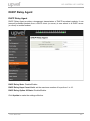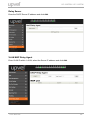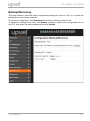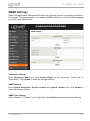
1
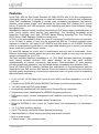
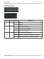
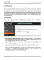
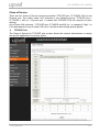
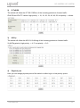
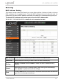
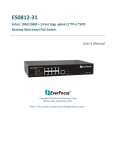
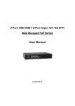
UP-308FEW / UP-316FEW
Table of Contents
Product Overview .................................................................................................................. 4
Package Contents ............................................................................................................... 4
Features ............................................................................................................................... 5
External Components Description .................................................................................... 6
LED Description .................................................................................................................. 7
Installation .............................................................................................................................. 8
Installation Site Requirements .......................................................................................... 8
Desktop installation ............................................................................................................ 8
Rack mounting .................................................................................................................... 8
Power connection ............................................................................................................... 8
Connecting to end nodes ................................................................................................... 9
Accessing the switch Web management GUI.................................................................... 10
Switch configuration ........................................................................................................... 11
Administrator .................................................................................................................... 11
Authentication Configuration ....................................................................................... 11
System IP Configuration ............................................................................................... 12
System Status ................................................................................................................ 13
Load Default Setting ...................................................................................................... 13
Firmware Update ............................................................................................................ 14
Reboot device ................................................................................................................ 14
PoE ..................................................................................................................................... 15
PoE Status ...................................................................................................................... 15
PoE Setting..................................................................................................................... 16
PoE Power Delay............................................................................................................ 17
PoE Scheduling.............................................................................................................. 18
NTP.................................................................................................................................. 18
Port Management .............................................................................................................. 19
Port Configuration ......................................................................................................... 19
Port Mirroring ................................................................................................................. 21
Bandwidth Control ......................................................................................................... 22
Broadcast Storm Control .............................................................................................. 23
User Manual
2
UP-308FEW / UP-316FEW
VLAN Setting ..................................................................................................................... 24
VLAN Mode ..................................................................................................................... 24
VLAN Member ................................................................................................................ 26
Multi to 1 Setting ............................................................................................................ 29
Per Port Counter ............................................................................................................... 30
QoS Setting ....................................................................................................................... 31
Priority mode .................................................................................................................. 31
Class of Service ............................................................................................................. 32
Security.............................................................................................................................. 34
MAC Address Binding ................................................................................................... 34
TCP/UDP Filter ............................................................................................................... 35
Web Security .................................................................................................................. 36
Spanning Tree ................................................................................................................... 37
STP Bridge Settings ...................................................................................................... 37
STP Port Settings........................................................................................................... 38
Loopback Detection....................................................................................................... 40
Trunking ............................................................................................................................. 41
DHCP Relay Agent ............................................................................................................ 43
DHCP Relay Agent ......................................................................................................... 43
Relay Server ................................................................................................................... 44
VLAN MAP Relay Agent................................................................................................. 44
Backup/Recovery .............................................................................................................. 45
Miscellaneous ................................................................................................................... 46
SNMP Settings .................................................................................................................. 48
Logout ................................................................................................................................ 49
Specifications ...................................................................................................................... 50
User Manual
3
UP-308FEW / UP-316FEW
Product Overview
UP-308FEW
UP-316FEW
Package Contents
• 8-/16-port PoE+ Switch
• Power cord
• Rack mounting kit: L-brackets (2 pcs) and screws (8 pcs)
• Rubber feet (4 pcs)
• Quick Installation Guide
• Warranty Certificate
Note. If any of the listed items are damaged or missing, please contact your distributor.
User Manual
4
UP-308FEW / UP-316FEW
Features
Upvel PoE+ 802.3at Web Smart Switches UP-308(316)FEW with 8-(16-)port configurations
significantly reduce cost of ownership for small and medium size business and professional
home PoE installations. Designed to provide easy accessible management and security
features, ample power supply, and bandwidth for high-power PoE outdoor Wi-Fi access
points, IP-cameras, and VoIP equipment, while complying with latest Green Ethernet Energy
savings features.
Management features include conditional monitoring of PoE power supply (available power of
ports, power supply delay, priority, and scheduling), Port Mirroring, broadcast storm
protection, VLAN (tag / port), QoS, TCP/UDP packet filtering, Spanning Tree, Port Trunking,
DHCP Relay, IGMP Snooping, SNMP, and many more.
All PoE+ ports automatically detect the class of connected Powered Devices and provision
up to 30 watts of power on each port as required per 802.3at. The total available power
regiment is limited at 140 watts for UP-308FEW and 260 watts for UP-316FEW. Electrical
power is transmitted along with data in one single cable allowing you to expand your network
where there are no power lines or outlets
For non-PoE devices the power feed is auto-blocked and only data is transmitted. Green
Ethernet technology features detect idle ports and cable length on each port and reduces
energy consumption by up to 75%.
The total available backbone bandwidth of 1.6 (3.2) Gbps provides necessary throughput
while limiting network overload. LED status displays on the front panel facilitate
troubleshooting of network connectivity and activity. Rack-mountable 1U steel housing
provides proper heat dissipation, and the fanless design guarantees zero operation noise.
Upvel UP-308(316)FEW switches facilitate fast deployment of high-performance secured
networks for both PoE and non-PoE devices. Proven performance, advanced control features
and high quality workmanship of switching components make it a great choice for expanding
office and home networks.
• 8 (16) x RJ-45 10/100 Mbps PoE+ ports w/ Auto MDI-X and Auto-negotiation, up to 30 W
per port
• Compliant with IEEE 802.3at and IEEE 802.3af Power over Ethernet standards
• 140 (260) watts total PoE power budget
• Automatically identifies the PoE class level of Powered Device connected
• Supports two-event classification for IEEE802.3at powered devices
• PoE power supply function management and condition monitoring using Web GUI and
SNMP
• Ability to set the maximum available power for each port
• Supports IEEE802.3x flow control for Duplex Mode and backpressure for Half-duplex
Mode
• 1.6 (3.2) Gbps switching capacity
• Up to 75% energy saving with Green Ethernet technology
• Rack-Mountable 1U Steel Housing (brackets and screws included)
• Built-in power supply
• Fanless design – zero operation noise
User Manual
5
UP-308FEW / UP-316FEW
External Components Description
Front panel of UP-308FEW
1~8
RJ-45 PoE+ 10/100 Mbps ports
Power
Power LED indicator
LNK/ACT 1~8
Ethernet connection/activity LEDs of the corresponding ports
PoE 1~8
PoE-enabled device connection LEDs of the corresponding ports
Reset
Factory Defaults Restore button
Front panel of UP-316FEW
1~16
RJ-45 PoE+ 10/100 Mbps ports
Power
Power LED indicator
LNK/ACT 1~16
Ethernet connection/activity LEDs of the corresponding ports
PoE 1~16
PoE-enabled device connection LEDs of the corresponding ports
Reset
Factory Defaults Restore button
Rear panel
The rear panel of the switch contains the AC power connector.
The switch supports 100~240 V AC, 50/60 Hz.
User Manual
6
UP-308FEW / UP-316FEW
LED Description
Indicator
Power
LNK/ACT
Color
Status
On
Power on
Off
Power off
On
Connection is established
Off
Connection is not established
Green
Green
Flashing
On
PoE
Green
Flashing
Off
User Manual
Description
Data is being transmitted
PoE-enabled device is detected
The power is insufficient for operation of PoE device
PoE-enabled device is not connected / detected
7
UP-308FEW / UP-316FEW
Installation
Installation Site Requirements
Ensure that the location where you plan to install the switch meets the following
requirements:
• Air temperature and humidity should be within the specified ranges (see technical
specifications on pp. 52, 53)
• Vent holes in the switch housing should not be blocked. Make sure that there is enough
space around the switch for proper ventilation and heat dissipation. Leave at least 10 cm
(4 inches) of space at the front and rear of the switch.
• The outlet should be close enough for the power cord to reach. The length of the power
cord supplied is 150 cm (59 inches).
Desktop installation
Place the switch on a sturdy, level surface that can support at least 5 kg (11 pounds). For
better stability, stick four rubber feet to the bottom of the switch near the corners.
Rack mounting
Attach the brackets to the switch using the included screws and then mount the switch on the
19-inch rack using the screws provided with the rack.
Power connection
1. Connect one end of the power cord to the AC power connector on the rear panel of the
switch, and then connect the other end of the power cord to an AC power outlet.
2. Check whether the Power LED is ON. When it is steady ON, it indicates the power
connection works properly.
User Manual
8
UP-308FEW / UP-316FEW
Connecting to end nodes
Use standard Cat.5/5e twisted pair cable (UTP/STP) to connect the switch to end nodes.
Switch ports will automatically adjust to the characteristics (MDI/MDI-X, speed, duplex) of the
connected devices.
After connecting all the devices required, you can configure various features of the switch
using its Web management interface. Management features include conditional monitoring of
the PoE power supply (available power of ports, power supply delay, priority, and scheduling),
Port Mirroring, broadcast storm protection, VLAN (tag / port), QoS, TCP/UDP packet filtering,
Spanning Tree, Port Trunking, DHCP Relay, IGMP Snooping, SNMP, and many more.
User Manual
9
UP-308FEW / UP-316FEW
Accessing the switch Web management GUI
1. Connect the switch to the computer, which you will use for configuring the switch.
2. Assign a Static IP address to the computer's network adapter in the subnet of
192.168.10.x (e.g. 192.168.10.100) and a subnet mask of 255.255.255.0
3. Open your web browser, type the IP address of
the switch in the address bar, and then press
Enter. The default IP address is 192.168.10.250.
4. Enter ID and Password, and then click OK.
By default:
ID: admin
Password: admin
Note: ID and Password are case sensitive.
5. The main page of Web management GUI will appear, as shown below.
User Manual
10
UP-308FEW / UP-316FEW
Switch configuration
Administrator
Authentication Configuration
This page allows to change the current username and password that are used to login the
switch web management interface.
Enter new Username and/or Password and then click Update to confirm changes. The
“Update Successfully” message will appear, as shown below. Click Reboot to reboot the
switch and re-login with the new settings.
User Manual
11
UP-308FEW / UP-316FEW
System IP Configuration
This page shows the current IP configuration of the switch including the IP Address, Subnet
Mask, Gateway and IP Configuration type (Static or DHCP).
You can change the IP settings of the switch according to your network configuration. If you
choose DHCP in the IP Configure field, the switch will act as DHCP client and will get the IP
address from the network DHCP server.
After changing the settings, click Update to confirm changes. The “Update Successfully”
message will appear, as shown below. Click Reboot to reboot the switch for the new settings
to take effect.
User Manual
12
UP-308FEW / UP-316FEW
System Status
This page shows the information about the switch: MAC address, firmware version and
number of ports.
The Comment field allows to set the switch name so that it could be easily identified in your
network.
You can also configure the Idle Time Security function here. If there is no user activity in
Web GUI for the specified Idle Time, the system will auto logout or back to the last display.
Click Update for the new settings to take effect.
Load Default Setting
This page allows to restore the factory default settings of the switch. Click Load to execute
factory defaults reset procedure. All current settings will be erased, excluding System IP
Configuration and Authentication Configuration. Then click Reboot to reboot the switch for
the new settings to take effect.
User Manual
13
UP-308FEW / UP-316FEW
Firmware Update
This page allows to update the firmware of the switch.
To execute the firmware update, you should enter the password in both Password and
Reconfirm fields, and then click Update.
The pop-up warning window will appear for making sure you want to proceed the firmware
updating procedure. Confirm to proceed the update.
The switch will erase the current firmware from its flash memory. Note. There is a selfprotection mechanism in the Boot Loader. Even if the power is turned off or the cable link fails
during the firmware update procedure, the Boot Loader will restore the code to firmware
update page.
Then another page will appear to select the firmware image file for upload. Click Browse to
select the file, and then click Update to continue the firmware updating procedure.
Upon completion of the firmware update, click Continue to reboot the switch and re-login.
Reboot device
This page is used to reboot the switch. Click Confirm to reboot.
User Manual
14
UP-308FEW / UP-316FEW
PoE
PoE Status
This page contains information about PoE functionality and allows to set the maximum
available power of all ports.
System operation status
Shows the PoE function status (On / Off).
Main Power Consumption
Indicates the total power consumption of PoE devices
connected to the switch.
Device Temperature #1 & #2 Readings of built-in temperature sensors.
Note. Changing the maximum available power requires reboot of the switch. Enter the
required value and click Update. In the pop-up message window, click OK to reboot the
switch for the new setting to take effect.
User Manual
15
UP-308FEW / UP-316FEW
PoE Setting
This page allows to configure the PoE function for each port.
Status
Enable/disable PoE for selected ports.
Mode
Select AF or AT mode according to the PoE standard (802.3af or 802.3at)
supported by the device connected to the port. The port provides up to 15.4 watts
in AF mode and up to 30 watts in AT mode.
Priority
Select the priority (Low, High or Critical) of powering the devices through the
selected ports.
Power
Budget
The maximum power provided by each of the selected ports. The value specified
in this field is multiplied by 0.1, thus for 10 W you should enter 100.
Port No.
Select the ports to which the settings should be applied.
All of the settings, excluding Mode, take effect immediately after clicking Update.
Changing the port mode requires reboot of the switch. After clicking Update the following
pop-up message appears:
Click OK to reboot the switch for the new settings to take effect.
User Manual
16
UP-308FEW / UP-316FEW
PoE Power Delay
This page allows to set a delay before supplying power to the ports once the switch is
powered on.
This may be useful if there are multiple high-power PoE devices connected to the switch (e.g.
outdoor surveillance cameras installed in enclosures with heater and fan). The start-up power
consumption of these devices is higher than their rated power, and simultaneous power-on of
multiple such devices may result in an overload of the switch power supply, which, in turn, will
activate the power supply overload protection.
Setting of PoE Power Delay prevents an overload of the switch power supply, since the highpower PoE devices are powered on sequentially.
To set a delay, select ports in Port No. field, choose Enable in Delay Mode field, enter the
desired Delay Time for the selected ports and click Update for the settings to take effect.
User Manual
17
UP-308FEW / UP-316FEW
PoE Scheduling
The PoE scheduling feature provides an hourly/weekly scheduling mechanism for advanced
power control. You can configure each PoE port to be ON or OFF on an hourly basis for
energy conservation and provision power only when needed.
NTP
This page allows you to select your local time zone and set the IP addresses of NTP servers
to synchronize the switch clock.
User Manual
18
UP-308FEW / UP-316FEW
Port Management
Port Configuration
This page allows to configure the operating mode of each physical port.
Auto
Auto-Negotiation Enable / Disable. If set to Enable, the Speed, Duplex
mode and Flow Control are negotiated automatically. If set to Disable, you
have to assign these parameters manually.
Speed
When Auto-Negotiation is set to Disable, you have to set the connection
speed for the selected ports. When Auto-Negotiation is set to Enable, this
item is read-only.
Duplex
When Auto-Negotiation is set to Disable, you have to set the connection
mode (Half or Full) for the selected ports. When Auto-Negotiation is set to
Enable, this item is read-only.
Pause
Flow Control in Full Duplex mode. When Flow Control is enabled, the
switch can synchronize the speed with its peer to avoid the packet loss
caused by congestion
Backpressure
Flow Control in Half Duplex mode. A condition wherein a switch causes a
transmitting device to hold off on sending data packets until the switch
bottleneck is eliminated.
Enable / Disable port. The default is Enable. If set to Enable, the port can
Tx/Rx Capability freely transmit and receive packets. If set to Disable, there will no access
to the network through the selected ports.
Addr. Learning
User Manual
Address learning is a service that characterizes a learning bridge, in
which the source MAC address of each received packet is stored so that
future packets destined for that address can be forwarded only to the
bridge interface on which that address is located.
19
UP-308FEW / UP-316FEW
Select Port No.: select the ports to which you want to apply the settings.
Click Update for the settings to take effect. The settings will be reflected in the status table.
Current Status: displays the status of each port.
For example:
This field indicates that the port 3 is linked up and run at 100 Mbps in Full Duplex mode with
Flow Control enabled.
Setting status: displays the configuration of each port.
User Manual
20
UP-308FEW / UP-316FEW
Port Mirroring
Port mirroring is used to send a copy of packets from one switch port (or an entire VLAN) to a
network monitoring connection on another switch port.
This feature allows to analyze and debug data and diagnose errors on a network, thus helps
network administrators keep a close eye on network performance and alerts them when
problems occur. It can be used to mirror either ingress or egress traffic (or both) on single or
multiple ports.
The Port mirroring function is accomplished by assigning the following items:
• Destination port (mirror port). A port that will be used to monitor traffic coming from the
source port(s). Theoretically, it is possible to set multiple destination ports in a network, but
actually the port mirroring function will lower the network throughput, and therefore it is
recommended to set only one destination port.
• Monitored packets. The type of traffic to be monitored: Rx – Received packets, Tx –
Transmitted packets, Tx & Rx – both Transmitted and Received packets.
Disable means the port mirroring function is disabled.
• Source port. The port to be monitored. All monitored port traffic will be copied (mirrored)
to the destination port. You can select multiple source ports, but note that port mirroring
function is bandwidth consuming. When multiple source ports are assigned, the
destination port may be congested.
Click Update to make the setting effective.
User Manual
21
UP-308FEW / UP-316FEW
Bandwidth Control
This page allows to set the maximum transmit/receive rate for each port.
Select the port number you want to configure, enter the desired values of Tx (transmit) and
Rx (receive) rates, select high or low speed base and click Update to make the settings
effective.
The actual port speed can be calculated by multiplying Tx/Rx Rate by the selected speed
base (32 or 512 kbps).
User Manual
22
UP-308FEW / UP-316FEW
Broadcast Storm Control
The broadcast storm control is used to block excessive broadcast packets. If the number of
broadcast packets exceeds the defined threshold during one time unit, all excessive
broadcast packets will be dropped. The time unit is 500 μs for 100 Mbps link speed and
5000 μs for 10 Mbps link speed.
Each port’s broadcast storm protection function can be enabled individually.
Example:
In the picture below, the Broadcast Storm Control is enabled for ports 1~6 and threshold is
set to 10. If the number of broadcast packets exceeds the threshold setting, all excessive
packets will be dropped (packet length is 64 bytes).
How to change one time unit to pps:
The port 1 is 100M port. The one time unit of it is 500 μs, it indicates that 2000 packets can
be sent within one second. Setting the threshold 10 for port 1 means that 10x2000 packets
can be sent in one second.
User Manual
23
UP-308FEW / UP-316FEW
VLAN Setting
A Virtual LAN (VLAN) is a logical grouping of network devices where the members can be on
different physical segments. It allows to isolate network traffic, so only the members of the
same VLAN will receive traffic from the ones of the same VLAN. Basically, creating a VLAN
from a switch is logically equivalent to reconnecting a group of network devices to
another Layer 2 switch. However, all the network devices are still plugged into the same
switch physically.
VLAN Mode
The switch supports Port-based and Tag-based VLAN modes. In port-based VLAN mode, the
tag setting is useless, since this mode is for separating traffic only on this single switch and
there is no handover of network traffic within VLAN groups to other switches. For traffic
handover to other switches, the tag-based VLAN mode should be used. When the tag-based
VLAN is selected, the user can define the handling method of a VLAN tag to the specified
port, including "Add Tag", "Remove Tag" or "Don’t care".
The default VLAN mode is port-based VLAN. To switch to tag-based VLAN mode, click
Change VLAN mode button. The following message will appear to ask for confirmation of
changing the mode.
Click Continue to proceed.
User Manual
24
UP-308FEW / UP-316FEW
After having switched to Tag Based VLAN Mode, the screen changes. On this screen, you
can define and configure Uplink and Downlink ports. These are important since here the
handover between the switches of your network takes place.
Tag Based VLAN Mode
VLAN Mode
Displays VLAN mode: Port-based / Tag-based VLAN. Here you can also
switch back to Port-based VLAN Mode
• Add Tag means the 802.1Q tag will be inserted in the outgoing packet of
the selected port. Use this setting for Up- and Downlink Ports in your VLAN
Tagged Network.
Tag Mode
• Don’t care means the outgoing packet of the selected port will be kept
original. This is the default setting when starting VLAN configuration. You
should change to either Add or Remove Tag.
• Remove Tag means the 802.1Q tag will be removed from the outgoing
packet of the selected port. Use this setting for network connections to
PCs. Only packets of the VLAN Group the port is a member of will be sent.
User Manual
25
UP-308FEW / UP-316FEW
VLAN Member
This page is used to assign ports as members of VLAN groups. The screen here looks
different whether you run Tag Based or Port Based Mode.
VLAN Member Setting in Port Based Mode
On the top screen, select the port you want to configure, click Read, and then select or
deselect the ports that are on the same VLAN group. In this configuration mode, there is no
need to worry about defining VLAN groups and VLAN IDs.
Click Update to make the configuration effective.
To clear the VLAN member selection, click Load Default.
In the following figure, ports 1~3 are set to same VLAN group and ports 4~8 are set to
another VLAN group.
User Manual
26
UP-308FEW / UP-316FEW
VLAN Member Setting in Tag Based Mode
In Tag-based Mode, you need to define and configure VLAN groups. Assign the VLAN ID,
select the VLAN member ports, assign the PVID and check the configuration result.
In the following figure, ports 1~7 are in the same VLAN group.
The port 2 tag VID number is 123.
• VLAN ID (VID)
For the handover to other switches to take place smoothly, the VLAN IDs (Numbers) need
to be like in the rest of your network.
On the other switches there may be was an option to set the names. These are just for
your reference. Only the numbers are important!
Add: Enter a VID, select the VLAN member for this entry and then press this button to add
a VLAN entry to the table. The available VID range is 1~4094.
Delete: Select a VID in the table and then press this button to remove a VID entry from the
table. After deleted, the VLAN and its member port settings are cancelled.
Update: This is for modifying the existing VLAN settings. Select the VID, the settings will
be displayed below, change the settings and then press the Update button to update the
settings.
• VLAN Member Port
Select the VLAN Member here.
User Manual
27
UP-308FEW / UP-316FEW
• VID Source Port
This table allows to set PVID of the port. Select the port number while you add VLAN and
select VLAN member ports. The selected ports’ PVID will be the VID you typed.
Please note that one port can have only one PVID. While one port joins multiple VLAN
groups, the PVID is important to identify where the incoming traffic will be forwarded to.
For example: Port 3 is the member of VLAN 100 and 200, PVID of port 3 is 100. The traffic
received from the connected PC is usually untagged, the incoming packets will then be
tagged with PVID within the switch and then follow the VID table for traffic forwarding.
• Port VID Map
This table shows the PVID of the ports.
• VLAN Member Table
This table shows the VID and its member ports.
Configuration Steps:
First, add your VLAN Groups, identified throughout your network by unique and constant
numbers. It often starts with IDs from 100 and up. Starting with 100 gives enough free
number space and less compatibility issues.
Second, enter 100 in the VID field, then select or deselect which ports are the members of
that group. All uplink and downlink ports must be the members of every existing group. If the
port joins different VLAN groups, the VID Source Port field allows to define the PVID.
After VLAN group is configured and member ports are selected, click Add to create the table
and related port mapping. The new group and its settings will be displayed in the table at the
bottom of the screen.
User Manual
28
UP-308FEW / UP-316FEW
Multi to 1 Setting
Multi-to-1 VLAN is used on CPE side of Ethernet-to-the-Home and is exclusive to VLAN
setting on “VLAN member setting”. When the VLAN member setting is updated, Multi-to-1
setting will be void and vice versa. The "disable port" means the port, which will be excluded
in this setting. All ports excluded in this setting are treated as the same VLAN group. In a
normal Tag Based VLAN network you will not need this configuration option.
There are two limitations for this setting:
1) The original setting of the VLAN group will be cleared and replaced by this special
structure if you enable this function. Conversely, if you set the VLAN Group again, this
special structure will be cleared and replaced by your newest setting.
2) This configuration is for Port-based VLAN only.
User Manual
29
UP-308FEW / UP-316FEW
Per Port Counter
This page shows packet statistics for each port.
Statistics are grouped into the following categories:
• Receive Packet & Transmit Packet: This category shows both the received packets
count (excluding the incorrect packets) and the transmitted packets count.
• Transmit Packet & Collision Count: This category shows the packets outgoing from the
switch and the count of collisions.
• Receive Packet & Drop Packet: This category shows the number of received valid
packets and the number of dropped packets.
• Receive Packet & CRC Error Packet: This category shows the number of received
correct packets and CRC errors. If your see an increased number of CRC errors, there
may be hardware issue. The possible reason could be a switch port failure, broken cable,
cable/fiber connector failure, etc.
Click Refresh to update the counter value.
Click Clear to reset the counter to 0.
Once you change the statistics category, the counter will be cleared automatically.
User Manual
30
UP-308FEW / UP-316FEW
QoS Setting
Here you can configure QoS priority mode and CoS (Class of Service). QoS (Quality of
Service) refers to mechanisms in the network software that make the actual determination of
which packets have priority. CoS refers to feature sets, or groups of services, that are
assigned to users based on company policy. If a feature set includes priority transmission,
then CoS winds up being implemented in QoS functions within the routers and switches in
the network. In an enterprise network, class of service (CoS) differentiates high-priority traffic
from low-priority traffic. Tags may be added to the packets to identify such classes, but they
do not guarantee delivery as do quality of service (QoS) functions, which are implemented in
the network devices.
Priority mode
There are three priority modes available to specify the priority of packets being serviced.
Those include First-In-First-Out, All-High-Before-Low (Strict Priority) and 4 Queue
Weighted Round Robin.
• First-In-First-Out: Packets are queued and serviced in the order they were received.
• All-High-Before-Low (Strict priority): All packets will be assigned to either high priority
queue (Queue 2) or low priority queue (Queue 1). The packet in the low priority queue will
not be forwarded until the high priority queue is empty.
• 4 Queue WRR: There are 4 priority queues for Weighted-Round-Robin (WRR) mode.
Q3 and Q4 are Low-weight queues (weight range: 0~8), Q1 and Q2 are High-weight
queues (weight range: 0~8).
In this mode, the switch will forward a specified number of high priority packets and then a
specified number of low priority packets. The switch repeats this cycle continuously.
Terms "low weight" and "high weight" mean the ratio of the packet in the transmit queue.
For example, if "low weight" and "high weight" are set to "3" and "5", the ratio of the
transmit packet for the low priority to high priority is 3/5.
When the queue weight is set to 0, it will be treated as 8.
User Manual
31
UP-308FEW / UP-316FEW
Class of Service
There are four Class of Service schemes provided: TCP/UDP port, IP ToS/DS, 802.1p and
Physical port. The switch treats CoS schemes in the following priority: TCP/UDP port >
IP ToS/DS > 802.1p > Physical port. It means that TCP/UDP CoS will override all other
settings.
Any of three CoS schemes – TCP/UDP port, IP ToS/DS and 802.1p – is mapped to "high", so
if the data packet hit any of these CoS rules, it will be treated as high priority packet.
1) TCP/UDP Port
The Class of Service for TCP/UDP port number allows the network administrator to assign
the specific application to a priority queue.
User Manual
32
UP-308FEW / UP-316FEW
2)
IP ToS/DS
The switch will follow the IP ToS / DiffServ of the incoming packets to forward traffic.
IPv4 DS and IPv6 TC values: high priority → 10, 18, 26, 34, 46, 48, 56; low priority → others.
3)
802.1p
The switch will follow the 802.1Q VLAN tag of the incoming packets to forward traffic.
VLAN Tag priority: high priority → 4~7; low priority → 0~3
4)
Physical port
Here you can assign physical ports of the switch to either high- or low-priority queue.
User Manual
33
UP-308FEW / UP-316FEW
Security
MAC Address Binding
This feature is also called Port Security on some other switches. It allows to bind up to three
MAC addresses to one physical port. Once the MAC address is bound to the port, only the
packets with the source MAC address specified in the table will be forwarded through this port.
The bound MAC addresses will not be aged out from the MAC address table.
"ff ff ff ff ff ff", "00 00 00 00 00 00" or blank will not be saved to the table.
MAC Address Enter the MAC address(es) you want to bind to the specific port.
Select Port
Select the port to which you want to bind the MAC address(es)
Binding
Enable or Disable. Select Enable to enable the MAC Address Binding
feature.
Update
After selecting the port, enabling Binding and entering MAC Address(es),
click Update to update and save the settings.
Read
Clicking Read button will show MAC addresses associated with the selected
port (if you’ve already entered any).
User Manual
34
UP-308FEW / UP-316FEW
TCP/UDP Filter
TCP/UDP filter allows to block some specific applications. There are two filtering rules
provided. The "Allow" rule makes the switch to forward the selected protocols and drop other
protocols. The "Deny" rule makes the switch to drop the selected protocols and forward other
protocols. The protocol is checked at the selected secure port.
Function Enable
Enable / Disable the function.
Port Filtering Rule
The outgoing packet with selected protocol will be either forwarded or
dropped at secure port.
• "Deny" means the selected protocol will be dropped and other
protocols will be forwarded.
• "Allow" means the selected protocol will be forwarded and other
protocol will be dropped.
Secure Port
Select the port(s) to which the filtering rule will be applied.
Protocol
Select the predefined protocol or User-defined Protocol, which will be
included in the filtering rule.
Click Update for the configuration to take effect.
User Manual
35
UP-308FEW / UP-316FEW
Web Security
This page allows to select which ports of the switch can be used to access the Web
Management GUI. With Web security enabled, the switch Web Management GUI will be
accessible only through the selected Access Ports.
User Manual
36
UP-308FEW / UP-316FEW
Spanning Tree
This switch supports IEEE 802.1D-2004 Rapid Spanning Tree Protocol (RSTP) and is
backward compatible with legacy Spanning Tree Protocol (STP) standards.
STP Bridge Settings
This page allows to configure STP Mode and time settings. See the description below.
STP Mode: Disable, STP, RSTP. Select the STP version you want to enable. The default
setting is Disable.
Bridge Priority: This parameter defines the spanning tree priority globally for this switch. The
switch with the lowest value has the highest priority and is selected as the root device. If all
devices have the same priority, the device with the lowest MAC address will then become the
root device. According to the protocol standard rule, the value must be a multiple of 4096 in
the range of 0 to 61440. Thus, there are 16 distinct values. If the value is changed, the switch
must be rebooted.
Hello Time: Interval (in seconds) at which the root device transmits a configuration message
(BPDU frame) to check current STP status. Enter a value between 1 through 10 (the default is 2).
Max Age: The maximum time (in seconds) a switch waits without receiving Spanning-tree
Protocol configuration messages before attempting to reconfigure. That also means the
maximum life time for a BPDU frame. Enter a value between 6 through 40 (the default is 20).
User Manual
37
UP-308FEW / UP-316FEW
Forward Delay: The maximum time (in seconds) the root device will wait before changing
from its Rapid Spanning Tree Protocol learning and listening states to the forwarding state.
Enter a value between 4 through 30 (the default is 15).
Click Submit for the configuration to take effect.
The Bridge Status table shows the STP configuration of the switch. The Root Status table
shows the Root Switch’s Information of the STP domain.
STP Port Settings
This page allows to set the STP port priority and its path cost.
After STP/RSTP is enabled, the priority and path cost are automatically assigned to the port.
Normally, it is necessary to change the parameters, however, you may need to control the
root switch or block port in some condition.
Select the port number, enter the values of the Priority and Root Path Cost and click
Submit to apply the settings.
User Manual
38
UP-308FEW / UP-316FEW
STP Port Settings table
Port No.: Choose one port of the Switch for further management.
Priority: Decide which port should be blocked by setting its priority as the lowest. Enter a
value between 0 through 240. The value of priority must be the multiple of 16.
RPC: The cost of the path to the other bridge from this transmitting bridge at the specified
port. Lower values should be assigned to ports attached to faster media, and higher values
should be assigned to ports with slower media. Enter a value between 1 through 200000000.
The default value is Auto.
STP Port Status table
Port No.: The switch port number of the logical STP port.
RPC: Root Path Cost. For the Root Bridge, it is zero. For all other Bridges, it is the sum of the
Port Path Costs on the least cost path to the Root Bridge.
Priority: The current priority for each port.
State: The current STP port state. The port state can be one of the following: Designated
port, Root port or Blocked port.
Status: The current STP port status. The port status can be one of the following: Forwarding,
Disable, Listening, Blocking, Learning.
Designated Bridge: ID of the STP Bridge which designated the root port.
Designated Port: Port number of the bridge from where the bridge designated the root port.
User Manual
39
UP-308FEW / UP-316FEW
Loopback Detection
Under some conditions, incorrect connection to wrong ports may cause a network loop. The
unknown broadcast and multicast may crash the whole network. The Loopback Detection
feature can help to prevent this type of situation.
Loopback Detection Function: Enable / Disable the Loopback Detection function.
The default setting is Disable.
Auto Wake Up: Enable / Disable the Auto Wake Up function. The default setting is Disable.
When the Loopback Detection function is running, the ports could be disabled to avoid the
loop. The Auto Wake Up function activates the port after Wake-Up Time Interval passed.
Wake-Up Time Interval: Select the time interval here. The default is 10 sec.
Click Submit to apply the settings.
User Manual
40
UP-308FEW / UP-316FEW
Trunking
Link Aggregation (Port Trunking) allows multiple links to be bundled together and act as a
single physical link. It provides higher throughput, load balancing, fault tolerance and
redundancy of links in a switched internetwork.
Traffic in a trunk is distributed across an individual link within the trunk in a deterministic
method that is called a hashing algorithm. The hashing algorithm automatically applies load
balancing to the ports in the trunk. In the event of a port failure within the trunk group the
network traffic will be directed to the remaining ports. Load balancing is maintained whenever
a link in a trunk is lost or returned to service. This switch may use Source MAC Address or a
combination of Source MAC Address and Destination MAC Address for the Trunk Hashing
Algorithm.
If the traffic pattern on the network is considered carefully and a proper hashing algorithm is
used, the traffic is kind of randomly decided to be transmitted across either link of the trunk
and load balancing will be seen.
Before making any physical connections between devices, it is necessary to configure the
link aggregation parameters of the devices at both ends. When using link aggregation, take
into account the following:
• The ports used in a link aggregation must all be for the same media type
(e.g. RJ-45, 100 Mbps).
• The ports can only be assigned to one link aggregation group.
• The ports at both ends of a connection must be configured as link aggregation ports.
• None of the ports in a link aggregation group (trunk) can be configured as a mirror source
port or a mirror target port.
• Enable the link aggregation prior to connecting cables between the switches to prevent
creating a switching loop.
• Disconnect all link aggregation port cables or disable the link aggregation ports before
removing a port link aggregation group to prevent creating a switching loop.
You can configure 2 link groups with a maximum of 4 ports aggregated in each group. If the
group is defined as a local static link aggregation group, then the number of ports must be
the same as the group member ports.
User Manual
41
UP-308FEW / UP-316FEW
System Priority: A value that identifies the active LACP. The switch with the lowest value
has the highest priority and is selected as the active LACP peer of the trunk group.
Link Aggregation Algorithm: Select the algorithm of link aggregation. The available options are:
• MAC Src&Dst – Hash Algorithm based on Source & Destination MAC Address XOR result.
• MAC Src – Hash Algorithm based on Source MAC Address
The default setting is MAC Src&Dst.
Member: Select the ports that will be the members of link aggregation group. Default link
group 1 includes P1, P2, P3, P4. Default link group 2 includes P5, P6, P7, P8.
State: Disable / Enable port trunk. The default setting is Disable.
Type: Select port trunk type: Static or LACP (Dynamic). The default setting is LACP.
When the LACP Trunk type is selected, the following parameters can be configured. Please
note that the parameters of ports that belong to one link aggregation group should be the
same on both ends.
Operation Key: Range: 1~65535. Default Link Group 1: 1; Default Link Group 2: 2.
Time Out: Select Long Time Out or Short Time Out. The Long Time Out is approximately
30 seconds, the Short Time Out is approximately 3 seconds, however, the link partner of
other supplier may not use the same value. The longer time out then will be used.
Activity: Select whether the link group is allowed (Active) to automatically send LACP
packets or not (Passive). The default setting is Passive.
User Manual
42
UP-308FEW / UP-316FEW
DHCP Relay Agent
DHCP Relay Agent
DHCP Relay Agent provides a transparent transmission of DHCP broadcast packets. It can
transmit broadcast packets from a DHCP client (or server) in one subnet to a DHCP server
(or client) in another subnet.
DHCP Relay State: Disable/Enable.
DHCP Relay Hops Count Limit: set the maximum number of hops from 1 to 16.
DHCP Relay Option 82 State: Disable/Enable.
Click Update to make the settings effective.
User Manual
43
UP-308FEW / UP-316FEW
Relay Server
Enter the DHCP Server IP address and click Add.
VLAN MAP Relay Agent
Enter VLAN ID within 1-4094, select the Server IP address and click Add.
User Manual
44
UP-308FEW / UP-316FEW
Backup/Recovery
This page allows to save the switch configuration settings to a file on a PC or to upload the
settings from a previously saved file.
To save the configuration, click Download and choose a folder to save the file.
To upload the settings from a file, click Browse to specify a path to the configuration file on
your PC, then enter the admin password and click Update.
User Manual
45
UP-308FEW / UP-316FEW
Miscellaneous
Miscellaneous Settings page allows to configure Output Queue Aging Time, VLAN Striding,
IGMP Snooping V1 & V2 and VLAN Uplink.
Output Queue Aging Time
This function prevents the situation when the traffic jam on one port may cause the
congestion of other ports. In some applications, e.g. IPTV Multicast communication, the
multicast stream is continuously generated from the source port, and the client port may be
congested because of the limited bandwidth or slow network processing ability. Then, the
Pause frame of Flow Control will be generated once the packet buffer is full. With the Output
Queue Aging Time function, a packet stored at an output queue for a long time will be aged
out and become a useless packet. You can set the Aging Time to 200, 400, 600 or 800 ms.
VLAN Striding
For some network environments, the network administrator may probably want to filter
undesired broadcast or multicast packets to enhance the network bandwidth utilization and
forward only meaningful unicast packets to a specific destination. VLAN is a good
mechanism to block broadcast packets, but it can also block unicast communication between
VLANs. To solve this issue, a special function called “VLAN striding” is designed. If VLAN
striding is enabled, the switch will forward unicast packets to the destination port, no matter
whether the destination port is in the same VLAN. The unicast packet can stride across
VLANs.
User Manual
46
UP-308FEW / UP-316FEW
IGMP Snooping V1 & V2
By default, a switch will flood multicast traffic to all ports in a broadcast domain. Multicast may
cause unnecessary load on host devices by requiring them to process packets they have not
solicited. The IGMP snooping feature allows the switch to listen in on the IGMP
communications between hosts and routers. By listening (also known as snooping) to these
communications, the switch maintains a map of which ports (clients) need which multicast
stream (source). Multicast that is not solicited by certain clients (or IGMP group) will be
filtered.
VLAN Uplink Setting
This switch does not implement an Independent VLAN (IVL) MAC address table, it utilizes
VLAN uplink to emulate the function of IVL. An independent VLAN MAC address table is
based on both the source MAC address and the VLAN. In some applications, if the switch
cannot build the separate MAC address table for different VLANs, there will be a conflict of
MAC address table. To solve this problem, the switch controller utilizes the VLAN Uplink port
to emulate the usage of Independent VLAN MAC Address Table.
VLAN Uplink function allows different VLANs to use individual uplink port to forward packets.
In a normal application, only one uplink port can be selected in a switch.
If VLAN Uplink function is enabled and the destination port of a unicast packet is located at
the next VLAN, this packet will be forwarded to the uplink port. Choose the Uplink Port X for
the port ID. The Uplink X will be the uplink port of its VLAN.
Note. There is a functional conflict between VLAN Striding and VLAN Uplink. So if both
VLAN Striding and VLAN Uplink are enabled simultaneously, the switch selects VLAN
Striding and ignores the VLAN Uplink setting.
User Manual
47
UP-308FEW / UP-316FEW
SNMP Settings
SNMP (Simple Network Management Protocol) is a popular protocol for managing devices on
IP networks. This page allows you to configure SNMP settings for monitoring and managing
your PoE+ Web Smart Switch.
Community settings
Enter Community Name and select Access Rights for the community: "Read only" or
"Read/Write". Click Update to make the settings effective.
SNMP Settings
Enter System Description, System Contact and System Location info. Click Update to
make the settings effective.
SNMP Trap Settings
Select "Enable" or "Disable" for the Trap State. Click Update to make the settings effective.
User Manual
48
UP-308FEW / UP-316FEW
Logout
When the switch configuration is finished, click Logout to leave the web management
interface. Login web page will appear.
User Manual
49
UP-308FEW / UP-316FEW
Specifications
UP-308FEW
Standards
IEEE 802.3 10BASE-T
IEEE 802.3u 100BASE-TX
IEEE 802.3af PoE
IEEE 802.3at PoE+
IEEE 802.3x Flow Control
IEEE 802.3az Energy Efficient Ethernet
IEEE 802.3ad Link Aggregation
IEEE 802.1Q VLAN
IEEE 802.1D STP, RSTP
Ports
8 x 10/100 Mbps PoE+ ports w/ Auto MDI-X and Auto-negotiation
Power over Ethernet
PoE: up to 15.4 W per port
PoE+: up to 30 W per port
Power budget: 140 W
PoE pins on RJ-45: 1&2 (+), 3&6 (-), mode A
Data Throughput
Ethernet: 10/20 Mbps (half-duplex / full-duplex mode)
Fast Ethernet: 100/200 Mbps (half-duplex / full-duplex mode)
Packet Forwarding Rate
10 Mbps: 14880 pps
100 Mbps: 148800 pps
Network Cables
10BASE-T: UTP/STP cat.5 (max. 100 m / 328 feet)
100BASE-TX: UTP/STP cat.5 or 5e (max. 100 m / 328 feet)
Switching Method
Store-and-Forward
Switching Capacity
1.6 Gbps
MAC Address Table
4K
LED Indicators
LNK/ACT
PoE
Power
AC Input
100~240 V AC, 50~60 Hz, internal power supply
Power Consumption
Standby: 8 W
Maximum: 160 W
Dimensions
280×180×44 mm / 11×7×1.7 inch
Standard 19" rack mounting width, 1U height
Weight
1.64 kg / 3.6 lbs
Temperature
Operating: 0 ~ 40 °C (32 ~ 104 °F)
Storage: -10 ~ 70 °C (14 ~ 158 °F)
Humidity
Operating: 10 ~ 90 % non-condensing
Storage: 5 ~ 90 % non-condensing
Certification
CE, FCC, Rostest
User Manual
50
UP-308FEW / UP-316FEW
UP-316FEW
Standards
IEEE 802.3 10BASE-T
IEEE 802.3u 100BASE-TX
IEEE 802.3af PoE
IEEE 802.3at PoE+
IEEE 802.3x Flow Control
IEEE 802.3az Energy Efficient Ethernet
IEEE 802.3ad Link Aggregation
IEEE 802.1Q VLAN
IEEE 802.1D STP, RSTP
Ports
16 x 10/100 Mbps PoE+ ports w/ Auto MDI-X and Auto-negotiation
Power over Ethernet
PoE: up to 15.4 W per port
PoE+: up to 30 W per port
Power budget: 260 W
PoE pins on RJ-45: 1&2 (+), 3&6 (-), mode A
Data Throughput
Ethernet: 10/20 Mbps (half-duplex / full-duplex mode)
Fast Ethernet: 100/200 Mbps (half-duplex / full-duplex mode)
Packet Forwarding Rate
10 Mbps: 14880 pps
100 Mbps: 148800 pps
Network Cables
10BASE-T: UTP/STP cat.5 (max. 100 m / 328 feet)
100BASE-TX: UTP/STP cat.5 or 5e (max. 100 m / 328 feet)
Switching Method
Store-and-Forward
Switching Capacity
3.2 Gbps
MAC Address Table
4K
LED Indicators
LNK/ACT
PoE
Power
AC Input
100~240 V AC, 50~60 Hz, internal power supply
Power Consumption
Standby: 8 W
Maximum: 270 W
Dimensions
442×208×44 mm / 17.4×8.2×1.7 inch
Standard 19" rack mounting width, 1U height
Weight
3.5 kg / 7.7 lbs
Temperature
Operating: 0 ~ 40 °C (32 ~ 104 °F)
Storage: -10 ~ 70 °C (14 ~ 158 °F)
Humidity
Operating: 10 ~ 90 % non-condensing
Storage: 5 ~ 90 % non-condensing
Certification
CE, FCC, Rostest
User Manual
51