1
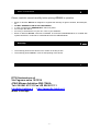
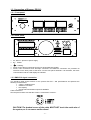
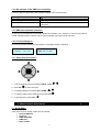
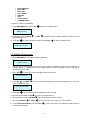
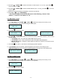
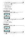
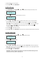
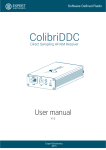
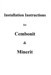
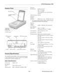
DP1213
Lighting Dimmer
User Manual ver. 1.53 ENG
-1-
-2-
Basic information
Please, read this manual carefully before placing DP1213 in operation
•
•
•
•
•
•
Block of dimmers DP1213 is designed to regulate the intensity of light in theatres, discotheques,
etc.
DO NOT DISMANTLE OR ALTER THIS DEVICE.
In case of malfunction, IMMEDIATELY switch off power.
Do not open the device.
Do not try to fix the device on your own. Turn to your distributor.
Block of dimmers DP1213 conforms to standard TU 3434-001-434800356758-06, is certified with
system ROSTEST, conformance certificate № РОСС RU.АЯ46.В16038.
Warranty
•
•
The warranty period for this device is 24 months of the day of sale.
The warranty period ceases in case of self-repairing of the device.
Manufacturer
DTS Illuminazione srl
Via Fagnano selve 10/12/14
47843 Misano Adriatico (RN) ITALIA
Tel +39 0541 611131 Fax +39 0541611111
[email protected]
http://www.dts-lighting.it
Made in Europe
-3-
Contents
Page
1. Basic characteristics
1.1 Technical characteristics
1.2 Installation
1.2.1 Bundling
1.2.2 Before installation
5
5
5
5
5
1.3 Connection of Dimmer DP1213
1.3.1 Front panel
1.3.2 Back panel
1.3.3 DMX-512 signal connection
1.3.4 An example of the DMX line connection
1.3.5 DMX line terminator structure
1.3.6 First switching on
1.3.7 Using the microprocessor
2. Menu pictures description
2.1 MAIN MENU
2.2 STATUS DEVICE mode
2.3 PROTOCOL mode
2.4 DMX ADDRESS mode
2.5 DMX FAULT mode
2.6 EDIT CURVE mode
2.7 EDIT PREHEAT mode
2.8 EDIT LIMIT mode
2.9 EDIT CUE mode
2.10 SOFT START mode
2.11 DISPLAY mode
2.12 FAN mode
2.13 SET BY DEFAULT mode
2.14 CHANNEL TEST mode
2.15 SETTINGS DISPLAY
3. Circuits protection
6
6
6
6
7
7
7
7
7
7
8
9
9
10
10
11
11
11
12
12
13
13
14
14
15
-4-
1. Basic Characteristics
•
•
•
•
•
•
•
Power supply: 380V, 3 PHASES + NEUTRAL. Frequency 50 Hz. Power supply of electronics by
one PHASE and NEUTRAL.
Max supply: 45А per PHASE.
Input control signal: DMX-512 (optoizolate).
Cooling system: forced air-cooling by cooler. Smooth rotation speed control depending on the
temperature of radiators.
Protection: output power circuits protected by electromagnetic circuit breakers (13A). Electronics
power circuit protected by a 0,25A safety fuse (situated on the board, near the feeding
transformer). Temperature control of the radiators provided by the microprocessor. With the
temperature of radiators above 80ºC, output signals are blocked.
Microprocessor: settings control from the front panel via the keyboard and the LCD display by
means of the menu.
Modes of operation: individual control of each channel from the operator’s desk, test-mode, “soft
start”-mode.
1.1 Technical characteristics
Power supply
Frequency
Number of channels
Max output each channels
Load
Interference-suppression filter
Power element
Control signals
Power supply connection
Load connection
Mounting
Block size, mm
Block weight, no more than, kg
Package size, mm
Overall weight, no more than, kg
380V (three PHASES + NEUTRAL)
50 Hz
12
2500VA
active or inductive
LC, 120 mcs
Inverse parallel SCRs, 35A
DMX-512
Terminals, 65A, 600V, 10sq.mm
Terminals, 30A, 600V, 4sq.mm
into rack
(W х D х H) : 482 x 424 x 132 (3U)h
14,5
(W х D х H) : 540 x 495 x 205
16,0
1.2 Installation
1.2.1 Bundling
•
•
Block of dimmers PD1213
Manual
1.2.2 Before installation
Please, read this paragraph carefully before installation.
•
•
•
•
•
•
This device is not designed for home use.
Do not switch on power until the device is ready for use.
All connections of the dimmer should be done by qualified staff.
Do not install close to sources of heat.
Install the dimmer in a well-aerated place. Do not block air-supply to the front and back panels of
the dimmer.
The dimmer should not be installed in the following places:
Wet places or places with very low or high humidity (less than 35% and more than
80%)
Places prone to vibration and strokes
Places with surrounding temperature below 2ºC and above 40ºC
CAUTION! The dimmer MUST be earthed!
-5-
1.3 Connection of Dimmer PD1213
1.3.1 Front panel.
1.3.2 Back panel.
•
•
L1, L2, L3 – phases of power supply.
N – neutral.
•
•
•
– earthing.
Power for the dimmer should be fed from a electromagnetic breaker.
Power, load connections and XLR-5pin connectors for DMX-512 connection are provided via
terminals on the back panel of the block. On the front panel automatic 13A switchers, the block
control buttons and the LCD display are situated.
1.3.3 DMX-512 signal connection
The interface cable should conform to the protocol EIA RS – 485 specifications and possess the
following characteristics:
2 wires + braded screen
resistance 120 Ohm
low capacity
provide max transmission speed of 250Kbit/s
Cable connection:
See the picture. Make sure that the screen is connected to contact 1.
CAUTION! The braded screen of the cable MUST NOT touch the earth wire of
the system, as it can cause malfunctions!
-6-
1.3.4 An example of the DMX line connection
In order to get true data keep to the following settings of the connection line:
250 m
32
Do not lay the cable close to power lines
A resistor of 120 Ohm between contacts 2 and 3 of the last
connector
Max length of the connection line
Max number of devices
Cable laying
Terminator structure
1.3.5 DMX line terminator structure
On the end of the DMX line a terminator should be installed. It is a resistor of 120 Om and power of
0.25W, situated between contacts 2 and 3 of the standard 3(5)-contact XLR connector.
1.3.6 First switching on
As soon as you have switched on the dimmer, the display reads the following:
DTS Illuminazione
DP1213 ver 1.53
____ ____ ____
DMX : No A : 001
1.3.7 Using microprocessor
1. To list through the menu use buttons RIGHT / LEFT
2. Press OK
.
to enter the menu.
3. To change settings use buttons UP / DOWN
.
4. To confirm change of the settings press button OK
.
5. To quit the menu press LEFT
.
2. Menu pictures description
2.1 MAIN MENU
In this menu dimmer setting modes can be selected:
• STATUS DEVICE
• Protocol
• DMX ADDRESS
• DMX fault
• EDIT CURVE
-7-
•
•
•
•
•
•
•
•
EDIT PREHEAT
EDIT LIMIT
EDIT CUE
SOFT START
DISPLAY
FAN
Set by default
CHANNEL TEST
To select a mode do the following:
while in the settings menu.
1. Enter MAIN MENU by pressing OK
*
MAIN MENU
Status Device
*
2. By pressing buttons RIGHT
(see paragraph 2.1).
3. Press OK
or LEFT
in the last line of the display select the mode you need
to enter the mode you need. Press LEFT
to quit the settings menu.
____ ____ ____
DMX : NO А : 001
2.2 STATUS DEVICE mode
1. Enter MAIN MENU. The display reads the following:
*
MAIN MENU
Status Device
*
In this mode the block of dimmers can be given a ‘name’ containing no more than 16 symbols, for
example SOFIT 1, RAMPA and the like. Capital letters of the Latin alphabet, ‘space’ and figures
from 0 to 9 may be used.
2. Press OK
to enter the mode, the display reads the following:
* STATUS DEVICE *
_____________
3. Press UP
or DOWN
of the 16 character cells.
to choose letters and figures you need (see paragraph 2.2.1) for each
* STATUS DEVICE *
R_ _ _ _ _ _ _ _ _ _ _ _
_
4. Press OK
, the cursor will move automatically to the next cell.
5. By pressing and retaining UP
you can move to the letter Z.
6. By pressing and retaining DOWN
you can move to the symbol ‘space’.
7. By pressing RIGHT
you can move the cursor from one cell to another.
or LEFT
8. To quit STATUS DEVICE mode use LEFT
press this button again.
to move the cursor to the leftmost position and then
-8-
2.3 PROTOCOL mode
1. Enter MAIN MENU. The display reads the following:
*
MAIN MENU
Protocol
2. Press OK
*
to enter the mode.
* PROTOCOL MENU *
DMX Patch OFF
#
3. Press UP
или DOWN
to select a mode.
* PROTOCOL MENU *
DMX Patch ON
4. Press OK
* PROTOCOL MENU *
MANUAL
to confirm, to the right of the mode name symbol # appears.
5. To quit the menu press LEFT
.
6. If DMX Patch ON mode is selected, in the last line of the settings menu symbol P appears.
____ ____ ____
DMX : NO А : 001 P
Input signal modes are the following:
• Patch Off - appellation of a DMX – address to the dimmer,
• Patch On - appellation of a unique DMX – address to each channel of the dimmer,
• Manual
2.4 DMX ADDRESS mode
1. Select MAIN MENU, press RIGHT
*
or LEFT
to select the mode.
MAIN MENU *
DMX Address
2. Press OK
to enter the mode. If the protocol mode is PATCH OFF (see paragraph 2.2), the
display reads the following:
* DMX ADDRESS *
First
DMX : 001
3. Press UP
ОК
*
or DOWN
to select the initial address of the DMX signal (from 1 to 512). Press
to confirm the selected address. The display reads the following:
MAIN MENU *
DMX Address
4. Press UP
to enter the mode. If the protocol mode is PATCH ON (see paragraph 2.2), the
display will read the following:
* DMX ADDRESS *
Ch : 01
DMX : 001
-9-
5. Press UP
or DOWN
move the cursor to DMX.
to select the number of channel (from 1 to 12 or AL), press OK
or DOWN
to select the DMX address (from 1 to 512), press OK
6. Press UP
cursor to Ch.
7. Repeat the actions described in paragraphs 5 and 6 for all channels.
8. Press LEFT
,
, move the
to quit to MAIN MENU.
! The factory default in the PATCH ON mode is the following: channel 1 has
address 1, channel 2 has address 2, etc.
2.5 DMX FAULT mode
1. Enter MAIN MENU, press RIGHT
or LEFT
to select the mode (in this mode you can
choose the reaction of the dimmer on losing the DMX signal).
*
MAIN MENU
DMX fault
2. Press OK
*
*
to enter the mode.
DMX FAULT
Level SAVE
*
#
*
DMX FAULT
Level RESET
*
#
*
DMX FAULT
*
Manual Emergency #
3. Press UP
or DOWN
to select one of the three modes of dimmer’s reaction in case of losing
the DMX signal.
• Level SAVE mode – the value of the latest DMX signal is saved.
• Level RESET mode – all the channels turn down if the DMX signal disappears.
• Manual Emergency – setting the output signals recorded in the memory of the device (in the
scene Cue: 13).
4. Press ОК
to confirm. In the last line of the display symbol # appears.
5. If Level RESET mode is selected, symbol F appears in the last line of the settings menu.
If Manual Emergency mode is selected, symbol E appears in the last line of the settings menu.
____ ____ ____
DMX : NO А : 001 PF
____ ____ ____
DMX : NO А : 001 PE
2.6 EDIT CURVE mode
1. Enter MAIN MENU, press RIGHT
or LEFT
to select the mode (in this mode you can
choose a law according to which each channel will be regulated).
*
MAIN MENU
Edit Curve
2. Press ОК
*
*
to enter the mode.
EDIT MENU
*
Ch : 01 Curve : LL
- 10 -
3. Press UP
or DOWN
to select the number of channel (from 1 to 12 or AL). Press ОК
or DOWN
move the cursor to Curve. Press UP
for the selected channel. Press ОК
,
to choose one of the 4 laws of regulation
.
4. The dimmer provides 4 laws of regulation:
• LL curve – linear law
• LS curve – luminosity linear law
• LQ curve – logarithmic law
• SR curve – switch on/off law.
5. Repeat paragraph 3 for all channels.
6. Press LEFT
to quit to MAIN MENU.
2.7 EDIT PREHEAT mode
1. Enter MAIN MENU, press RIGHT
or LEFT
to select the mode (in this mode you can
choose the preheat rate of filaments for each channel of the dimmer).
*
MAIN MENU
Edit Preheat
2. Press ОК
*
to enter the mode.
*
EDIT MENU
*
Ch : 01 Preheat : 00
3. Press UP
or DOWN
to select the number of channel (from 1 to 12 or AL). Press ОК
move the cursor to Preheat. Press UP
20%). Press ОК
or DOWN
,
to choose the preheat rate (from 0 to
.
4. Repeat paragraph 3 for all channels.
5. Press LEFT
to quit to MAIN MENU.
2.8 EDIT LIMIT mode
1. Enter MAIN MENU, press RIGHT
the luminosity for each channel).
*
MAIN MENU
Edit Limit
2. Press ОК
*
or LEFT
to select the mode (in this mode you can limit
*
to enter the mode.
EDIT MENU
*
Ch : 01
Limit : FF
3. Press UP
or DOWN
to select the number of channel (from 1 to 12 or AL). Press ОК
move the cursor to Limit. Press UP
Press ОК
or DOWN
.
- 11 -
to choose the limit (from 100% to 20%).
,
4. Repeat paragraph 3 for all channels.
5. Press LEFT
to quit to MAIN MENU.
2.9 EDIT CUE mode
1. Enter MAIN MENU, press RIGHT
programming CUE (max 13)).
*
MAIN MENU
Edit CUE
2. Press ОК
or LEFT
to select the mode (in this mode you can
*
to enter the mode (the cursor is on cue C:).
*
EDIT CUE
*
C: 01 Ch : 01 Lv : 00
3. Press UP
or DOWN
to select the number of cue C: (from 1 to 12 or 13 (cue uses the
Manual Emergency mode). Press ОК
DOWN
, move the cursor to channel Ch:. Press UP
to choose the Channel (from 1 to 12, or AL). Press ОК
or
, move the cursor to level
Lv:. Press UP
or DOWN
to choose the level (from 0% to 100%). Press ОК
To repeat paragraph 3 for all channels.
.
4. Press LEFT
to quit number of cue C:.
5. Press LEFT
to quit to MAIN MENU. All the cues are recorded in the flash memory of the device.
2.10 SOFT START mode
1. Enter MAIN MENU, press RIGHT
*
MAIN MENU
Soft start
2. Press ОК
*
*
*
#
or DOWN
to select one of the two modes: Status OFF (“soft start” mode off) or
Status ON (“soft start” mode on). Press ОК
its maximum value in about 0.2 seconds.
4. Press LEFT
to select the mode.
to enter the mode.
SOFT START
Status : OFF
3. Press UP
or LEFT
. When the mode is on, the output signal achieves
to quit to MAIN MENU.
CAUTION! All the settings of the dimmer are saved in the flash memory and are
available even after power is switched off.
- 12 -
2.11 DISPLAY mode
1. Enter MAIN MENU, press RIGHT
the display illumination).
*
MAIN MENU
Display
2. Press ОК
or LEFT
to select the mode (in this mode you can control
*
to enter the mode.
* DISPLAY MENU *
LED : Always on #
*
DISPLAY MENU *
LED : Auto off
#
3. Press UP
or DOWN
to select one of the two modes: Always On or Auto Off (the
illumination turns off automatically in 40 seconds after the latest pressure of any button). Press ОК
to confirm. In the last line of the display symbol # appears.
4. Press LEFT
to quit to MAIN MENU.
2.12 FAN mode
1. Enter MAIN MENU, press RIGHT
*
MAIN MENU
FAN
2. Press ОК
or LEFT
to select the mode FAN.
*
to enter the mode.
*
FAN MENU *
FAN: Lin SPEED: FF
*
FAN MENU *
FAN: Int SPEED: FF
*
FAN MENU *
FAN: On SPEED: FF
*
FAN MENU *
FAN: Off SPEED: FF
3. Press UP
or DOWN
to select режим работы FAN
• FAN: Lin – fan performance is changed depending on radiators temperature. As soon as
radiators temperature achieves the rate of +32ºС, the fan starts at speed one, then speed
increases in proportion to the rise in temperature. When radiators cool down to about +27ºС
the fan switches off,
• FAN: Int – should at least 2 channels of the dimmer reach the rate of 50% or 4 channels of
the dimmer reach the rate of 10%, the fan turns to max speed. The fan switches off within 30
sec after all the channels fall to 0%,
• FAN: On – the fan is ALWAYS ON independently of reading of the temperature sensor,
• FAN: Off – the fan is OFF! The fan switches on automatically at maximum speed, should
temperature of at least one radiator of the dimmer exceed +50ºС, and remains on until the
temperature falls to about +30ºС.
4. Press ОК
, move the cursor to SPEED: FF. Press UP
or DOWN
speed of the fan. The speed rate lies between 37 and 100%. Press ОК
5. Press LEFT
to quit to MAIN MENU.
- 13 -
to choose the max
.
2.13 SET BY DEFAULT mode
1. Enter MAIN MENU, press RIGHT
factory default).
*
MAIN MENU
Set by default
2. Press ОК
or LEFT
to select the mode (all the settings return to
*
to enter the mode.
Set by default !
Are you sure ?
3. Press simultaneously LEFT
and RIGHT
to confirm. All the settings will return to factory
default. All the settings will return to factory default.
____ ____ ____
DMX : NO А : 001
2.14 CHANNEL TEST mode
1. Enter MAIN MENU, press RIGHT
*
MAIN MENU
Channel Test
2. Press ОК
*
or LEFT
to select the mode.
*
to enter the mode.
TEST MENU
*
Ch : 01
Level : 00
3. Press UP
or DOWN
to select the number of channel (from 1 to 12, or AL), press OK
move the cursor to Level. Press UP
100%). Press ОК
or DOWN
to choose the output signal rate (from 0 to
, the cursor will move to Ch.
4. Repeat paragraph 3 for all channels.
5. Press LEFT
to quit to MAIN MENU.
2.15 SETTINGS DISPLAY
1. Enter MAIN MENU, press RIGHT
or LEFT
,
. The display will read the following:
____ ____ ____
DMX : ОК А : 001
The first line reads channels level.
The last line shows the following information:
• DMX availability DMX : OK
• DMX absence DMX : NO, the display light twinkles (to attract staff’s attention)
• Signal receipt error DMX : ER, the display light twinkles
• Initial block address in PATCH OFF mode
- 14 -
•
First channel address in PATCH ON mode
2. Press RIGHT
or LEFT
, now you can see the following:
TºC : 24 23
Pwr : Ok Ok Ok
3. The first line reads the temperature of block radiators (in ºC), the last line reads availability of all
phases of the feeding network – symbol OK (in case the phase is off – symbol Bad).
4. Enter MAIN MENU, press LEFT
. The display will read the following (mode CUE):
____ ____ ____
MANUAL CUE : 01
The first line reads channels level.
The last line shows the following information:
• Mode MANUAL
• Number CUE
5. Press RIGHT
or LEFT
, now you can see the following:
STATUS DEVICE
RAMPA
The first line reads STATUS DEVICE.
The last line shows the following information – the given name of the block.
3. Circuits protection
3.1 Temperature protection: the maximum temperature of any of the radiators can achieve the rate
of 80ºС. When this rate is achieved, the dimmer’s outputs turn to “off”. The display reads the
following:
The display light starts to blink
TºC : Hi 23 ALARM
Pwr : Ok Ok Ok
Having cooled down, the dimmer starts again.
3.2 Protection of disappearing of one or two phases: if the voltage of phase L2 or L3 of the power
circuit disappears, the following message is displayed:
The display light starts to blink
TºC : 23 24 ALARM
Pwr : Ok Bad Bad
After the breakdown is dealt with, the dimmer starts again.
3.3 Load protection is provided by 13A electromagnetic breakers.
- 15 -
The information contained in this publication has been carefully prepared and checked. However, no
responsibility will be taken for any errors. All rights are reserved and this document cannot be copied,
photocopied or reproduced, in part or completely, without prior written consent from D.T.S. D.T.S.
reserves the right to make any aesthetic, functional or design modifications to any of its products
without prior notice. D.T.S. assumes no responsibility for the use or application of the products or
circuits described herein.
D.T.S. Illuminazione s.r.l_Via Fagnano Selve 10-12-14_47843 Misano Adriatico (RN) Italy
Tel. +39 0541 611131_Fax +39 0541 [email protected]_ www.dts-lighting.it
- 16 -