1
JBaby
A dissertation submitted in partial fulfilment of
the requirements for the degree of
BACHELOR OF ENGINEERING in Computer Science
in
The Queen's University of Belfast
by
Anonymous
2 May 2006
Declaration of Originality
I declare that this report is my original work except where stated.
Signed ____________________________ Date _______________________
1
ACKNOWLEDGEMENTS
I would like to thank the various people who helped test the system. Without their
participation the system would not be as robust and stable. I would especially like to
thank, Fiona Sullivan, Jamie Addis, John Eakin, Philip Johnston and David Hewitt for
the time and effort that they dedicated to thoroughly testing the system.
I would also like to thank Professor D. Crookes, my project supervisor, for dedicating
his time for his assistance and advice in the design, implementation and
documentation of my project.
2
ABSTRACT
The development of motor skills are extremely important in a child’s development
and can help children perform better in other, more academic and physical ways.
However the teaching of these invaluable skills is often forgotten about or ignored.
The aim of this researched based project was to build a system to address this issue
using cheap, everyday technology.
The final system works extremely well and
successfully completes its purpose, which was to analysis if a child is clapping in
time with an audio sequence. With further research and development, systems like
this one, could be successfully used to help children improve motor skills such as
rhythmic clapping.
3
DECLARATION OF ORIGINALITY.................................................................................................1
ACKNOWLEDGEMENTS...................................................................................................................2
ABSTRACT ............................................................................................................................................3
1. INTRODUCTION..............................................................................................................................6
1.1 OVERVIEW......................................................................................................................................6
1.2 BACKGROUND INFORMATION .........................................................................................................6
2.0 REQUIREMENTS ANALYSIS ......................................................................................................7
2.1 HOW THE PROBLEM IS CURRENTLY SOLVED ...................................................................................7
2.2 THE SHORTCOMINGS OF THE CURRENT SOLUTION ..........................................................................7
2.3 PROPOSED NEW SYSTEM ................................................................................................................7
2.4 FUNCTIONAL REQUIREMENTS ........................................................................................................8
2.4.1.1 Video and Image Processing Requirements................................................................................... 8
2.4.1.2 Core Audio Requirements ............................................................................................................. 9
2.4.3.1 Video ........................................................................................................................................... 10
2.4.3.2 Audio........................................................................................................................................... 10
2.5 FAMILIARISATION.........................................................................................................................11
3. FUNCTIONAL SPECIFICATION ................................................................................................13
3.1 DATA MODEL ...............................................................................................................................13
3.2 FUNCTIONAL SPECIFICATION DEFINITION ....................................................................................15
3.2.1.1 Core Video and Image Processing Functions .............................................................................. 15
3.2.1.2 Core Audio Functions.................................................................................................................. 20
3.3 FUNCTIONAL SPECIFICATION FOR THE CHILD ...............................................................................21
3.4 FUNCTIONAL SPECIFICATION FOR THE OPERATOR........................................................................22
3.5 FUNCTIONAL SPECIFICATION FOR THE OPERATOR IN RESEARCH MODE ........................................24
4. DESIGN ............................................................................................................................................27
4.1 GRAPHICAL USER INTERFACE DESIGN .........................................................................................27
4.1.1.2 Structure of the menu items......................................................................................................... 29
4.1.1.3 Description of the non-obvious menu items ................................................................................ 30
4.1.1.4 Image Processing Control Panel.................................................................................................. 32
4.1.1.5 Audio Control Panel .................................................................................................................... 33
4.1.1.6 Segmented Video Sequence ........................................................................................................ 33
4.1.1.7 Information Area ......................................................................................................................... 34
4.3 SOFTWARE DESIGN ......................................................................................................................36
4.3.4.1 Control Data ................................................................................................................................ 39
4.3.4.2 Video capture interface................................................................................................................ 40
4.3.4.3 Frame Processing......................................................................................................................... 40
4.3.4.4 Image processing ......................................................................................................................... 41
4.3.2.5 Feature-extraction........................................................................................................................ 46
4.3.2.6 Motion Interpretation................................................................................................................... 48
4.3.2.9 Feedback generation .................................................................................................................... 49
5. IMPLEMENTATION......................................................................................................................51
5.1 TECHNOLOGY USED .....................................................................................................................51
5.2 IMPLEMENTATION OF COMPONENTS .............................................................................................52
5.2.2 Control Data ................................................................................................................................... 53
5.2.4 Frame processing............................................................................................................................ 56
5.2.5.2 ComponentLabelling ................................................................................................................... 60
5.2.6.2 Speed ........................................................................................................................................... 63
5.2.6.3 Direction...................................................................................................................................... 63
5.3.10 Child Feedback............................................................................................................................. 66
5.3.11 Utility Classes............................................................................................................................... 66
6. TESTING ..........................................................................................................................................67
6.1 WHITE BOX TESTING.....................................................................................................................67
6.2 BLACK BOX TESTING ....................................................................................................................67
4
6.2 TEST CONCLUSIONS ......................................................................................................................68
7. CONCLUSION.................................................................................................................................69
7.1 EVALUATION ................................................................................................................................69
7.2 FINDINGS ......................................................................................................................................69
7.2 FUTURE ENHANCEMENTS .............................................................................................................70
7.3 SUMMARY ....................................................................................................................................71
REFERENCES .....................................................................................................................................72
APPENDICES ......................................................................................................................................74
5
1. INTRODUCTION
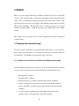
1.1 Overview
The aim of this project is to build a computerised system which uses vision to capture
a child’s movements and has a musical/audio output which will help stimulate
movement. This system will help children develop co-ordinated movements in their
hands and arms and accomplish simple tasks such as rhythmic clapping.
1.2 Background information
It has been medically proved that children’s motion control and co-ordination is
extremely important in a child’s development and can encourage them to perform
better in other, more academic and physical ways. Therefore stimulating children’s
motion control and co-ordination is extremely important and an area which can not be
neglected.
6
2.0 REQUIREMENTS ANALYSIS
2.1 How the problem is currently solved
The problem starting point, assumes that the child can already clap and the objective
is to encourage rhythmic clapping. This is currently solved by a guardian teaching
children rhythm using a variety of techniques. One such technique is to get the child
to clap in time with music. The guardian will then note and reward how well the
child is clapping in time with the music. Another technique is to encourage the child
to repeat rhythms which have been clapped out by the guardian.
2.2 The shortcomings of the current solution
One-to-one attention isn’t cost effective for child minders. Parents don’t always have
enough time to spend teaching children these invaluable skills.
Therefore the
teaching of skills such as rhythmic clapping can get neglected.
Another problems is that it is difficult to quantify how well the child is keeping in
time with the music.
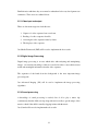
2.3 Proposed New System
The proposed system is essentially an experiment to investigate the technology
aspects, which if successful could open up the possibility of developing a full system
for real life use.
The system will use vision to capture a child’s movements and have a musical/audio
output to help stimulate co-ordinated, rhythmic clapping from the child. Visual
feedback will be given to show the child how well they are clapping in time with the
music.
To simplify the task of determining the movements we envision that the child will
wear coloured gloves.
7
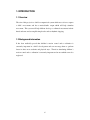
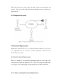
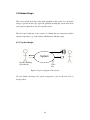
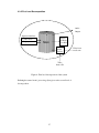
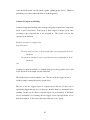
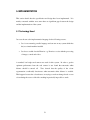
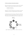
There will be three users of the system; the child, operator in research mode and
operator. The users and how they will interact with the system are shown in the
diagram below.
2.3.1 Diagram of the system
Figure 1: Top level diagrammatic view of the system.
2.4 Functional Requirements
Requirements marked with a star (*) are additional features which are not part of the
core requirements but are extra, non essential requirements which add extra
functionality to the system.
2.4.1 Core Functional Requirements
There are a number of core functional requirements which are carried out by the
system but don’t require any input from a user. These can be grouped together under
two categories, video and image processing requirements and audio requirements.
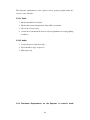
2.4.1.1 Video and Image Processing Requirements
8
1. Capture of a video stream from a web camera.
2. Opening a video sequence from a file.
3. Segmentation: Separation of the hands from the background.
4. Display of original video sequence.
5. Display of segmented video sequence.
6. Motion detection: Record motion properties (the direction, distance and speed
each hand has moved between every frame)
7. Motion interpretation: The system will classify the current motion into one of
five categories;
a) Hands moving apart
b) Hands moving together
c) Hands still
d) Hands touching
e) Other (for any other scenarios which don’t fit into any of the above
categories)
2.4.1.2 Core Audio Requirements
1. A music clip can be played continuously.
2. The tempo of the music clip can be detected.
3. The tempo of the music clip is software controllable.
2.4.2 Functional Requirements for the Child
1. The child interacts with the system by attempting to clap in time with the
music.
2. Visual feedback will be provided to the child, so they know how well they are
clapping in time with the music.
2.4.3 Functional Requirements for the Operator
9
The functional requirements for the operator can be grouped together under two
sections, video and audio.
2.4.3.1 Video
1. Monitor the child’s movements.
2. Monitor the systems interpretation of the child’s movements.
3. Choose the colour to track.
4. Control the colour thresholds for more robust segmentation in varying lighting
conditions.
2.4.3.2 Audio
1. Control the speed of the music clip *
2. Select the music clip to be played *
3. Mute music clip
2.4.4 Functional Requirements for the Operator in research mode
10
1. Choose to run the program either live or from video file for testing purposes.
2. Facilities for optimising and calibrating the separation of the hands from the
background;
i. Provide the option of average thresholding.
ii. Provide the option of background thresholding.
3. Experiment with applying various appropriate pre-processing imaging
operations to investigate the trade-off between quality of segmentation and
speed of operation. In particular, the operator should be able to experiment
with and without;
i. Open (to remove speckle and noise)
ii. Close (to close small gaps e.g. avoid a hand being split in two)
4. Single step through a video sequence for analysis purposes *
5. Analysis Functions.
The system will display the results of the motion
interpretation (2.4.1.1(6)) and also other details such as the location of each
hand, and the distance, direction and speed each hand has moved between the
previous frame and the current.
2.4.5 Non Functional Requirements
1. The system must have an intuitive and easy to use front end interface.
2. The live video frames must be processed in real time
3. A low cost web cam must be used.
2.5 Familiarisation
11
Familiarisation with three key areas must be undertaken before any development can
commence. These areas are outlined below.
2.5.1 Video input and output
There are four main stages involved this area;
1. Capture of a video sequence from a web cam.
2. Reading of a video sequence from file.
3. Accessing the video sequence frame by frame.
4. The display a video sequence
Java Media Framework (JMF) will be used to implement the above tasks.
2.5.2 Digital Image Processing
Digital image processing is an area which deals with analyzing and manipulating
images. An extensive knowledge of this are is needed in order to successfully extract
useful and meaningful information from the video sequence.
The separation of the hands from the background is the most important image
processing task.
Java Advanced Imaging (JAI) will be used to implement the image processing
algorithms.
2.5.3 Sound processing
A knowledge of sound processing is needed, first of all to play a music clip
(continuously) that the child can clap along with and secondly to get the tempo of the
music to check if the child is actually clapping in time with the music.
Java Sound will be used to implement the above tasks.
12
3. FUNCTIONAL SPECIFICATION
This section further defines the functional requirements set out in the Requirements
Analysis Section (Section 2)
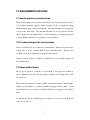
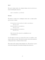
3.1 Data Model
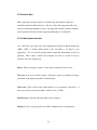
A data model (figure 2 on the next page) is needed to introduce the basic functions of
the system and to show how they interact. It also introduces the variables which are
used later in the functional specification section. The display areas are also included
in the data model.
Note: Although in practice the system will process one frame at time, we
conceptually regard and process all frames and intermediate frames sequences as a
block. This notion will be used throughout the functional specification section.
13
Display Areas
videoFile
videoWebCam
previousFrame
currentFrame
0
1
videoStreamWin
n-1
displays
videoStream
videoStream
Input can be either from a
web camera or a video file
segmentedVideoWin
0
1
n-1
segmentedVideoSeq
This the output after the
hands have been separated
from the background
displays
segmentedvideoSeq
propertiesWin
0 1
n-1
XPositionHand1
XPositionHand2
displays
XDistanceHand1,
XDirectionHand1
XSpeedHand1,
XDistanceHand1,
XDirectionHand,
XSpeedHand1
interpretationWin
XDistanceHand1
displays
interpretation
XDirectionHand1
XSpeedHand1
interpretation
XDistanceHand2
XDirectionHand2
XSpeedHand2
feedbackWin
Graphical feedback for
the child
Controls for specifying different
options and values
musicClip
integer: tempoMusic
• OpenOption
integer: newTempo
• CloseOption
float: tempoClapping
• ThresholdBackgroundOption
frame: image1
• ThresholdAverageOption
frame: image2
• colourThreshold
frame: image3
• tempoControl
frame: image4
• selectMusicClip
Figure 2: A Data model of the proposed system
14
3.2 Functional Specification Definition
All of the requirements specified in the requirements section (section 2) are set out
under the following headings;
•
Core system functions
•
Functions for the operator
•
Functions for the operator in research mode
Each function is described by a table with the following fields;
•
Inputs: Data which is passed into the function
•
Behaviour: A definition, in terms of the data model of what the function does
•
Pre-protocols: External actions or events that need to occur before the
function can begin
•
Post-protocols: The state of the system after the function has completed
•
Error conditions: Any error conditions that should be checked for
3.2.1 Core System functions
These are core system functions which are not specifically carried bout by any user
but by the system itself. These functions can be further divided into two sections;
core video and image processing functions and core audio functions.
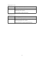
3.2.1.1 Core Video and Image Processing Functions
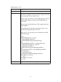
Requirement 2.4.1.1(1)
Name
Capture the video stream from a web camera
Inputs
videoWebCam
Behaviour
Change input to input from a web camera
Pre-conditions
videoStream = videoWebCam
Web camera is plugged in and is not being used by another
application
15
Requirement 2.4.1.1(2)
Name
Read video sequence from file
Inputs
videofile
Behaviour
Change input to input from a file
Pre conditions
videoStream = videoFile
File exists
Error conditions
File contains a valid video sequence
16
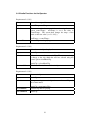
Requirement 2.4.1.1(3)
Name
Segmentation
Inputs
videoStream
Behaviour
This function accepts as an input, the original video sequence
and returns a segmented version of the video sequence and a list
of non-connected objects, ranked by size.
The first stage of the function is thresholdBackground. This is a
function which subtracts an image of the background from
every frame.
The next stage is thresholdAverage. This segments the frame
using brightness.
colourSegmentation is the final segmentation stage, it is not
optional and segments the frame by colour.
Open and close are optional post processing functions which
clean up the image.
for all i
if thresholdBackOption is selected
thresholdBackgroundVideo =
thresholdBackground(segmentedVideoSeq)
else
thresholdBackgroundVideo = segmentedVideoSeq
if thresholdAverageOption is selected
thresholdAverageVideo =
thresholdAverage (thresholdBackgroundVideo)
else
thresholdAverageVideo = thresholdBackgroundVideo
if colourSelected
segmentedVideoSeq =
colourSegmentation(thresholdBackgroundVideo)
if openOption is seletected
open()
if closeOption is selected
close()
Pre conditions
User has selected the colour of the gloves to track
17
Requirement 2.4.1.1(4)
Name
Display of original video sequence
Inputs
videoStream
Behaviour
Display takes videoStream as an input and returns a window
displaying this video sequence.
videoStreamWin = display(videoStream)
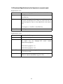
Requirement 2.4.1.1(5)
Name
Display of segmented video sequence
Inputs
segmentedVideoSeq
Behaviour
Display takes segmentedVideoSeq as an input and returns a
window displaying this video sequence.
segmentedVideoWin = display(segmentedVideoSeq)
18
Requirement 2.4.1.1(6)
Name
Record motion properties for each hand
Inputs
SegmentedVideoSeq
Behaviour
This function records the following motion properties
• distance
• direction
• speed
These values are worked out my comparing the hand position in the
current frame (frame i) with the position of the same hand in the
previous frame (i-1)
Note: This can’t start until i>1 (to stop a frame which doesn’t exist
being accessed).
for all i
XPositionHand1[i] = findXPositionHand1()
XPositionHand2 [i] = findXPositionHand2()
XDistanceHand1 =
disanceBetween( XPositionHand1[i] , XpositionHand1[i-1] )
XDistanceHand2 =
disanceBetween( XPositionHand2[i] , XpositionHand2[i-1] )
XDirectionHand1 =
direction( XPositionHand1[i] , XpositionHand1[i-1] )
XDirectionHand2 =
direction( XPositionHand2[i] , XpositionHand2[i-1] )
XSpeedHand1 = speed(XDistanceHand1)
Error
conditions
XSpeedHand2 = (XDistanceHand2)
If the segmentation gives less than two objects. The motion
properties are only recorded for that one object (this occurs when the
hands are touching)
19
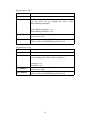
Requirement 2.4.1.1(7)
Name
Motion interpretation
Inputs
XDirectionHand1, XDirectionHand2
Behaviour
Accepts as inputs the direction hand 1 is moving and the
direction hand 2 is moving and returns a classification of the
current motion; hands moving apart, hands moving together,
hands still and apart, hands touching or other for any
classification which doesn’t fit into the first four categories.
interpretation = interpret(XDirectionHand1, XDiectionHand2)
3.2.1.2 Core Audio Functions
Requirement 2.4.1.2(1)
Name
Start playing a music clip continuously
Inputs
newMusicClip
Behaviour
If there is a music clip being played, it will end and the new
music clip will begin to play. Otherwise the new music clip
will begin to play
Post conditions
musicClip = newMusicClip
Continuously playing music clip
Requirement 2.4.1.2(2)
Name
Detect the tempo of the music clip
Inputs
musicClip
Behaviour
Accepts a music clip as an input and returns the tempo of the
music clip.
tempoMusic = findTempo(musicClip)
Requirement 2.4.1.2(3)
Name
Set the tempo of the music clip
Inputs
tempoMusic, musicClip
Behaviour
Acepts as an input a music clip and an integer value. It changes
the tempo of the music to the integer value.
Post conditions
changeTempo(musicClip, tempoMusic)
musicClip with its tempo changed to the value of tempoMusic
20
3.3 Functional Specification for the Child
Requirement 2.4.3.2(1)
Inputs
The child interacts with the system by attempting to clap in time
with the music.
Child clapping along with the music
Behaviour
The system records the tempo of the child’s claps.
Name
tempoClapping = tempo of the child’s clap
Requirement 2.4.3.2(2)
Name
Inputs
Behaviour
Visual feedback will be provided to the child, so they know
how well they are clapping in time with the music.
tempoClapping, tempoMusic
Interpret the current motion and then display “encouragement”
for the child. There are five different levels of encouragement
(i.e. very good, good, ok, bad, very bad).
It is sufficient to determine the absolute value of the quality of
clapping, rather than having a dynamic improvement function
which would smile if the child started to improve, even though
he or she is still not clapping in time with the music.
feedbackWin = display(tempoClapping, tempoMusic)
21
3.4 Functional Specification for the Operator
The functions for the operator can be divided into two sections; video and image
processing functions for the operator and audio functions for the operator.
3.4.1 Video and Image Processing Functions for the Operator
Requirement 2.4.3.1(1): Monitor the child’s movements
The operator can monitor the child’s movements by watching the videoStreamWin
display area. This displays the original video sequence, and so by watching this
display area the operator can monitor the child’s movements.
Requirement 2.4.3.1(2) Monitor the system’s interpretation of the child’s movements.
The operator can monitor the system’s interpretation of the child’s movements by
watching the interpretationWin classifies the current motion into one of following
five scenarios;
•
Hands moving apart
•
Hands moving together
•
Hands still
•
Hands touching
•
Other (for anything scenario which doesn’t fit into the above four categories)
Requirement 2.4.3.1(3)
Name
Inputs
Behaviour
Pre conditions
Control the colour thresholds for more robust segmentation in
varying lighting conditions.
colourThreshold, videoStream
A value (chosen by the user) is passed into the segmentation
method. By changing this value, the user can optimise the
quality of the segmentation
for all i
sementedVidSeq =
segmentation(videoStream[i], colourThreshold)
Segmentation has actually started (i.e. the user has picked a
colour to track)
22
3.4.2 Audio Functions for the Operator
Requirement 2.4.3.2(1)
Name
Control the tempo of the music
Inputs
controlTempo, newTempo
Behaviour
The user controls the tempo of the music using the control
option controlTempo. newTempo is set to the value of
controlTempo. The system then changes the tempo of the
music to this new value ( see 3.1.2.2(3) )
Pre conditions
newTempo = controlTempo
A music Clip must be playing
Requirement 2.4.3.2(2)
Name
Select the music clip to be played
Inputs
musicClip
Behaviour
Allows the user to choose a musicClip. The current music clip
is change to the clip which the user has selected using the
control option selectMusicClip.
Error conditions
musicClip = selectMusicClip
The chosen file must be a valid music clip
Requirement 2.4.3.2(3)
Name
Mute music clip
Inputs
musicClip
Behaviour
Accepts as an input a music clip and returns the musicClip with
the volume muted.
Pre conditions
musicClip = mute(musicClip)
A music clip must be playing
Post conditions
musicClip
23
3.5 Functional Specification for the Operator in research mode
Requirement 2.4.4(1)
Name
Choose to run the program either live or from a video file
Inputs
videoFile
videoWebCam
Behaviour
The function changes the video sequence to a video source from
the newly selected input mode. If the user selects file, the user
must be prompted to enter or select what file he or she wants to
play.
videoSequence = videoFile or videoWebCam
Post conditions
videoSequence
Requirement 2.4.4(2a)
Name
Control threshold average
Inputs
thresholdAverageOption
Behaviour
The user can turn the threshold average option off and on from
the control area (by changing the control variable
thresholdAverageOption).
thresholdAverageOption = on
thresholdAverageOption = off
Pre conditions
Segmentation must be running (i.e. the user must have clicked
on an object to track)
Post conditions
Segmentation occurs using thresholdAverage if the option is
turned on, otherwise threholdAverage isn’t used.
24
Requirement 2.4.4(2b)
Name
Control threshold backround
Inputs
image2
Behaviour
The user can turn the threshold background option off and on
from the control area (by changing the control variable
thresholdBackgroundOption).
thresholdBackgroundOption = on
thresholdBackgroundOption = off
Pre conditions
Segmentation must be running (i.e. the user must have clicked
on an object to track)
Post conditions
Segmentation occurs using thresholdBackground if the option is
turned on, otherwise threholdBackground isn’t used.
Requirement 2.4.4(3a)
Turn open on
Name
Inputs
openOption
Behaviour
The user can turn the open option off and on from the control
area (by changing the control variable openOption).
openOption = on
Pre conditions
Post conditions
openOption = off
Segmentation must be running (i.e. the user must have clicked
on an object to track)
Segmentation occurs using thresholdBackground if the option is
turned on, otherwise threholdBackground isn’t used.
25
Requirement 2.4.4(3b)
Turn close on
Name
Inputs
closeOption
Behaviour
The user can turn the close option off and on from the control
area (by changing the control variable closeOption).
closeOption = on
Pre conditions
Post conditions
closeOption = off
Segmentation must be running (i.e. the user must have clicked
on an object to track)
Segmentation occurs using thresholdBackground if the option is
turned on, otherwise threholdBackground isn’t used.
Requirement 2.4.4(4)
Single step through video sequence for analysis purposes
Name
Inputs
videoSequence
Behaviour
currentFrame = videoSequence[head]
head = head + 1
Input must be from a video file and not from a web camera
Error conditions
Requirement 2.4.4(5)
The information returned from the motion properties function (2.4.1.1(6)) and the
motion interpretation (2.4.1.1(7)) function will be displayed in the propertiesWin and
interpretationWin respectively.
26
4. DESIGN
There are various design methodologies which could have been used to design this
system e.g. the waterfall model, evolutionary prototyping model and the incremental
model. The evolutionary prototyping model has been used in this system. This
approach was chosen because prototyping is ideal when the requirements are not fully
known at the beginning. This approach allows a working prototype to be up and
running extremely quickly. Using this prototype, the requirements can be further
refined.
This design section is split up into two sections; graphical user interface design and
software design.
4.1 Graphical User Interface Design
Since this system is intended as an experimental research project, it was decided to
have a single operator interface (i.e. one interface for the operator and the operator in
research mode). The child has a user interface of his or her own.
4.1.1 Graphical user interface for operator including research mode
From the Functional Specification (Section 3) it was decided that the user interface
(for the operator and operator in research mode) should contain 5 display areas;
•
The input video sequence
•
Segmented video sequence
•
Motion properties (e.g. distance, direction and speed for each hand)
•
System’s interpretation of the child’s movements including the feedback
given to the child (e.g. hands moving together, hands moving apart, hands
touching)
•
A control panel for optimising and controlling the image processing
operations and to control the tempo of the audio sequence.
27
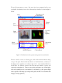
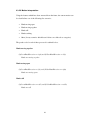
For good layout purposes, some of the areas have been compacted and are not
rectangular. An annotated screen shot of the actual user interface is shown in figure 3
below.
Image processing
Control Panel
Menu
Control
Panel
Audio
Control
Segmented
Video
Sequence
Input
Video
Information
Area
Motion
Interpretation
Motion Properties
Child feedback
Figure 3: User Interface for the operator and operator in research mode
The user interface consists of a desktop pane, with smaller internal windows sitting
on top of this pane. The decision was taken to use internal windows, so that any of
the displays areas (windows) can easily be disposed of. A user interface like this is
needed since two different operators share the same user interface (operator and
operator in research mode). The user can position and remove any of the display
areas and essentially create a user interface to suit himself (e.g. the operator might
want to get ride of the image processing control panel, since he is not concerned with
image processing operations)
28
4.1.1.2 Structure of the menu items
Table 1 below, shows the structure of the menu, along with a brief description each
menu item.
File
Open
Opens a video file
Quit
Exit the system
Input Source
Video File
Selects input from a video file
Web Camera
Selects input from a web camera
Audio
Select Audio Sequence
List of Songs
User selects audio clip from the list of songs
Audio Sequence
Mute/unmute audio sequence
Clapping Sound Effect
Mute/unmute clapping sound effect
Window
Image Processing Control Panel
Display/remove image processing control panel
Audio Control Panel
Display/remove audio control panel
Input Video Sequence
Display/remove input video sequence
Segmented Video Sequence
Display/remove segmented video sequence
Information Area
Display/remove information area
Child feedback
Display/remove the child feedback area
Table 1: Table showing the structure of the menu system
A more detailed description of some of the menu items is required. This is given on
the following page, along with pseudo code for the event handlers which will be
carried out when the user clicks on the menu item.
29
4.1.1.3 Description of the non-obvious menu items
1. Open
Open is a function which allows the operator to choose the video file which is to be
played. When the operator clicks on open a file chooser dialog box appears, from
which the user can choose a video file. The pseudo code for the event handler is
outlined below.
Display file chooser
OK: video Sequence = video file which the user chooses
Cancel: video Sequence = previous video Sequence
2. Video File
The menu item video file, changes the input source from a web camera to a video file.
When this menu item is clicked on, an open dialog box will appear allowing the user
to select a video file. The pseudo code for this event handler will not be shown, since
it is essentially the same as the event handler for the open menu item which was
described above.
3. Window
The audio control panel will be used an example, however the behaviour is the same
for each of the windows. If the audio control panel is currently displayed on the
screen and the user clicks on the menu item audio control panel, the window will be
disposed of. The next time the user clicks on this menu item, the audio control panel
will be redrawn in the user interface. Each of these windows can also, be disposed of
by clicking on the ‘x’ which is located on the top right hand side of all of the
windows. If the window is disposed of in this manner, it can be brought back by
clicking on the appropriate menu item.
30
The event handler for each of the windows is essentially the same therefore a generic
variable ‘window’ has been used in the pseudo code below.
If window is currently displayed on the screen
Dispose of window
Else
Display window
4. Select Audio Sequence
When this menu item is clicked on, a sub menu will appear listing a number of audio
sequences. The selected audio sequence will start to play
31
We now present the GUI design, showing how the requirements are to be realised
through the GUI;
4.1.1.4 Image Processing Control Panel
This area contains the following controls to optimise and fine tune the segmentation
process;
Open
Turns the morphology operation ‘open’ on or off (requirement 2.4.4(3a))
Close
Turns the morphology operation ‘close’ on or off (requirement 2.4.4(3b))
Threshold (Background)
Turns the thresholding operation ‘thresholdBackground’ on or off (requirement
2.4.4(2a))
Threshold (Average)
Turns the thresholding operation ‘thresholdAverage’ on or off (requirement2.4.4(2b))
Hue, Saturation and Brightness
These are three sliders which are used to optimise and control the colour
segmentation.
Refresh
Use to refresh the segmented video sequence after any of the above operations have
been applied (used when in single stepping through video sequence mode)
32
4.1.1.5 Audio Control Panel
Contains a slider to change the tempo of the music (requirement 2.4.2.1(1))
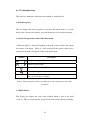
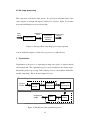
Input Video Sequence
The input video sequence can be from a video file or from a web camera. If the input
is from a video file the operator has additional controls over the video sequence.
These controls are to step through the video sequence one frame at a time.
Step forward one
Pause
Play
Step backward one frame
Figure 4: The video controls
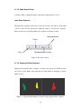
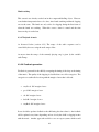
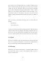
4.1.1.6 Segmented Video Sequence
Displays the segmented video sequence, coloured coded (green for the hand on the
left, yellow for the hand on the right and red if the hands are touching) as shown
figure 5 below
Figure 5: A diagram illustrating the coloured coded segmented video sequence
33
4.1.1.7 Information Area
This window contains three information areas which are outlined below.
1. Motion Properties
This area displays the motion properties as text from the current frame i.e. for each
hand, in the x direction, the distance, speed and direction moved since the last frame.
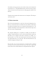
2. System’s Interpretation of the Child’s Movements.
A different symbol is displayed depending on how the system classifies the current
movements of the hands.
Below is a table showing all the symbols which can be
displayed along with a description of what each symbol means.
Symbol
Description
Hands moving apart
Hands moving together
Hands still but not touching
Hands touching
Other. No symbol is displayed if the current scene can’t be classified
into one of four above scenarios.
Table 2: Table showing the symbols representing the system’s interpretation of the child’s
movements
3. Child feedback
This display area displays the same visual feedback which is given to the child
(see4.1.2). This is to ensure that the operator knows who well the child is performing
34
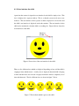
4.1.2 User interface the child
Apart from the camera for input, the user interface for the child is simply a face. This
face is displayed in a separate window. This is so that the system can be run on two
monitors. The user interface for the operator would be displayed on one monitor and
the child’s user interface is displayed on the other monitor. The user interface for the
child can be maximised so that the child sees nothing else. Figure 6 below shows the
user interface for the child.
Maximise
window
Figure 6: Screen shot of the user interface for the child
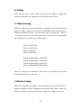
There are five different faces which are displayed depending on how well the child is
clapping in time with the music. A smiley face is displayed when the child is keeping
in time with the music and a frown is displayed when the child is completely out of
time with the music. The five different faces are shown in figure 7 below.
Figure 7: The feedback which is given to the child
35
4.3 Software Design
This section details the design of the main algorithms in the system. It is structured
using a top down analysis type approach, gradually breaking the system down from
very general components to into more specific objects.
The first logic breakdown of the system is to identify the user interactions and the
external components (e.g. a web camera) which interact with the system.
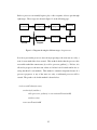
4.3.1 Top level design
System
Operator including
research mode
Video
File
Figure 8: Top level diagram of the system
We now further decompose the system component to give us the first level of
decomposition.
36
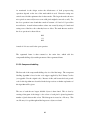
4.3.2 First Level Decomposition
Audio
Output
Operator interface
Control areas
Display areas
Main
Display
feedback
For child
Video
capture
interface
Video
from a file
Figure 9: First level decomposition of the system
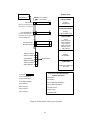
Refining the central ‘main’ processing object gives us the second level of
decomposition.
37
Video from
a web cam
4.3.3 Second Level Decomposition
Control Data
Main Controller
Feedback Generation
Child
Feedback
quality of clapping
Control
Areas
New
Tempo
Audio
output
Playback of music
tempo of claps
Motion Interpretation
motion properties
Display
Areas
Feature Extraction
Image
processing
controls
Video
Playback
controls
labelled set of objects
Image Processing
frame
Frame Processing
Video
capture
interface
Figure 10: Second level decomposition of the system
Rather than further decomposition, we now give some further details on each of the
components shown in figure 10 above.
38
4.3.4 Design of components
This section discusses each of the components shown in figure 10 on the previous
page. The image processing component is by far the largest and therefore requires
quite an extremely detailed and lengthy design description. The control and display
areas component will not be discussed in this section since in was discussed in great
length in the graphical user interface design (section 4.1).
4.3.4.1 Control Data
The control data is all the options and values that the user can change through the user
interface. These values influence various parts of the system.
New Tempo
This variable can be changed using a slider (show in figure 3) and the tempo of the
music is update accordingly;
audioTempo = newTempo
were audioTempo is the tempo of the currently playing audio track
Image Processing Controls
Hue, saturation and brightness are sliders which are used to fine tune the
segmentation process. The values of the sliders are stored as integers and are passed
into the image processing component.
39
A variable needs to be used to indicate the status of each of the following operations,
all of which can be on or off at any one time;
•
Open
•
Close
•
Threshold (Average)
•
Threshold (Background)
Video Playback Controls
These controls influence the playback of the video sequence, when running the
program from a video file. Play and pause both use the same variable. Play sets step
to false and pause sets step to true. When step is set to true the automatic frame
processing is stopped and won’t start again until the play button is pressed. When the
program is in the state the forward and backward buttons are used to control the
playing of the video sequence.
4.3.4.2 Video capture interface
The video capture interface is responsible for accepting an input from either a video
file or a web camera and producing a video sequence as an output. This video
sequence will then be passed into the frame processing object.
4.3.4.3 Frame Processing
The frame processing object takes a video sequence as an input and splits the video
sequence up into frames.
These individual frames are passed into the image
processing object.
40
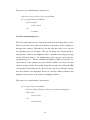
4.3.4.4 Image processing
This component is the heart of the system. It is passed an individual frame of the
video sequence as an input and outputs a labelled set of objects. Figure 11 below the
shows the individual processes involved in this.
segmented
frame
video
frame
Segmentation
Connected
Component
Labelling
Labelled set of
objects
Figure 11: Decomposition of the image processing component
A more detailed description of each of above processes is outlined below.
1. Segmentation
Segmentation is the process of separating an image into regions of interest (hands)
and a background. The segmentation process can be divided into two distinct stages,
thresholding and post processing. Both of these processes can be further divided into
smaller components. This is shown in figure 12 below.
Thresholding
Original
Frame
Threshold
Background
Threshold
Average
Colour
Segmentation
Post Processing
Segmented
Image
Open
Close
Note: Process doesn’t start until the user clicks a colour to track
Figure 12: Breakdown of the segmentation process
41
a) Thresholding
Thresholding is the process of converting a colour image into a black and white
image. The regions of interest (hands) are turned white and everything is else is
changed to black.
As can be seen from figure 10 there are three distinct stages in the thresholding
process. The first two stages are optional and can be turned off or on by the user.
These processes can improve the quality of the segmentation. The third process
thresholds the image by colour. These processes are described in more detail below.
Threshold Background
ThresholdBackground compares every pixel in the current frame to a frame taken of
the background by itself. If the pixel (of the current frame) is within a certain colour
distance of the background pixel, it is set to black, otherwise it is left as it is.
Threshold background essentially removes the background from every frame, leaving
an image of the child against a black background.
The pseudo code of this function is outlined below;
for every pixel Pij in currentFrame
if Pij lies within colour distance of backgroundPixel ij then
set Pij to black
else
do nothing
Threshold Average
Threshold average takes an average grey level value for the current frame. It sets
every pixel which is brighter than this value to a background pixel (i.e. black). This
function works on the assumption that the background will generally be a brighter
colour (white, cream etc.) than the objects which are to be tracked.
42
The pseudo code of this function is shown below;
avgback = average greylevel of the currentFrame
for every pixel Pij in currentFrame
if Pij > avgback
set Pij = black
else
do nothing
b) Colour segmentation process
The colour segmentation process separates the hands from the background by colour.
The user selects the colour of the object which he or she wants to track by clicking on
the input video sequence. When the user does this a Boolean value is set to true and
the segmentation process will begin. The user can change the colour thresholds by
using the hue, saturation and brightness sliders contained in the image processing
window (shown in figure 3). By changing these values the user can fine tune the
segmentation process. The hue, saturation and brightness (HSB) colour model was
chosen instead of the standard red, green and blue (RGB) colour model because
extensive testing of both colour models (using the prototype) proved that the HSB
colour model produced better results. This is because, the colour of the gloves should
have the same hue value throughout, however it could have different saturation and
brightness values because of the variations in lighting conditions.
The pseudo code of this function is shown below;
for every pixel Pij in currentFrame
if Pij lies within valid range of the hue, saturation and brightness
slider values
set Pij to white
else
set Pij to black
43
1. Post-processing
Post-processing is used to clean up binary images. It fills in holes and removes
isolated noise pixels. There are two processes involved in this; open and close. Open
and close are both formed using two mathematical morphology operations; erosion
and dilation. Erosion removes isolated noise pixels and smoothes object boundaries.
However it also removes the outer layer of object pixels i.e. the object becomes
slightly smaller. Dilation fills in holes and smoothes object boundaries. However it
adds an extra outer ring of pixels onto the object boundary i.e. the object becomes
slightly larger. The problem with erosion and dilation is that they change the size of
the objects. To overcome this we can combine erosion and dilation to form two new
operations known as open and close.
a) Open
Opening is used to remove `salt noise' in image (i.e. white noise pixels amongst a
black background). An open is an erosion followed by a dilation. The amount of
white pixels which are removed depends upon the size of mask which is used for the
open operation.
b) Close
Closing is used to remove `pepper noise' in images (i.e. black noise pixels amongst a
white background). A close is an dilation followed by a erosion. The amount of
black pixels which are removed depends upon the size of mask which is used for the
close operation.
The order of the two morphology operations is very important and affects the
outcome of the post processing stage. It has been decided to perform a close first,
followed by an open. By performing the operations in this order, the black speckle in
the objects (hands) is removed first. If the operations were carried out in the opposite
44
order, the black speckle could be joined together, splitting up the objects. Therefore
performing a close first reduces the chances of this happening.
Connected Component Labelling
Connected component labelling scans an image and groups its pixels into components
based on pixel connectivity. Each group is then assigned a unique colour value
according to the component that it was assigned to.
The pseudo code for this
operation is shown below
Initialise each pixel to a unique value
Loop three times
From top hand left corner, to bottom right hand corner propagating the local
maximum
From bottom right hand corner to top left hand corner propagating the local
maximum
end
Connected component labelled is a standard image processing operation and so will
be not discussed in any length of detail at this time.
The labelled objects are then ranked by size. The area of the two biggest objects is
found by simply counting the pixels for each object.
The area of the two biggest objects is compared and if the area of object one is
significantly bigger than the area of object two then the hands are determined to be
touching. In this case all objects except the largest one are discarded. If the hands
are not determined to be touching, the two biggest objects are kept and the rest of
them are discarded. So this object will return either one or two objects.
45
4.3.2.5 Feature-extraction
Now the hands have been separated from the background, the motion properties can
be extracted. There are three motion properties to be extracted for each hand; the
centre co-ordinates in the horizontal (x) direction, the speed and the direction. Each
one of these properties will now be discussed in more detail.
The centre co-ordinates in the horizontal (x) direction
A decision has been taken to ignore the vertical position of the hands. This is because
by using co-ordinates in the horizontal direction and the area, we have enough useful
information to interpret the current frame (this is discussed in more detail in the next
section)
Since each hand will be labelled with a different colour, we can substitute the variable
colourOfObject with the colour of the object we want to calculate the area for.
Pseudo code for finding the co-ordinates in the x direction:
Total = sum of all x co-ordinates of all pixels of object
Centre = total/sum
for every pixel Pij in currentFrame
{
if Pij = colourOfObject
total = total + i
else
do nothing
}
x = total/area
46
Speed
The speed is simply worked out by taking the distance moved over the last two
frames and dividing this result by two;
Speed = (currentCentre – prevCentre)/2
Direction
The direction is worked out by examining the current centre co-ordinate and the
previous centre co-ordinate;
If (currentCentre and previousCentre lie within a certain distance)
Direction = still
Else If (currentCentre < previousCentre)
Direction = right
Else if (currentCentre > previousCentre)
Direction = left
Where direction will be replaced by greenHandDirection and
yellowHandDiretion.
Note: The hands do not have to be exactly still in order to be classified as such,
instead a small leeway is given. This decision was taken to allow for the variations in
working out the centre co-ordinate from frame to frame.
These features will be displayed in the information area. They will also be passed
into the motion interpretation object which will interpret the current motion.
47
4.3.2.6 Motion Interpretation
Using the features which have been extracted from the frame, the current motion can
be classified into one of the following five scenarios;
•
Hands moving apart
•
Hands moving together
•
Hands still
•
Hands touching
•
Other (for any scenarios which doesn’t fit into one of the above categories)
The pseudo code for each of these processed is outlined below;
Hands moving together
if (GreenHandDirection == right) and (YellowHandDirection == left)
Hands are moving together
Hand moving apart
if (GreenHandDirection == left ) and (YellowHandDirection == right)
Hands are moving apart
Hands still
if (GreentHandDirection == still ) and (YellowHandDirection == stillt)
Hands are still
48
Hand touching
This scenario was already worked out in the componentLabelling object. However
some further interpretation has to be done, since hands touching and hands clapping
are not the same. The hands are only said to be clapping during the first frame of
when the hands are touching. When this occurs a timer is started and the time
between claps is worked out.
4.3.4.7 Payback of music
As discussed before (section 4.3.3) The tempo of the audio sequence can be
controlled by the user, using the audio tempo slider.
At anyone time the tempo of the currently playing song is given by the variable
audioTempo.
4.3.2.9 Feedback generation
Feedback is generated for the child by comparing the timing of the claps to the timing
of the music. The quality of the clapping is classified into one of five categories. The
categories are outlined below along with the margin of error that is allowed;
•
veryGood: 10% margin of error
•
good: 20% margin of error
•
ok: 40% margin of error
•
bad: 60 % margin of error
•
veryBad: 80% margin of error
It was decided to produce feedback to the child using absolute values i.e. the feedback
will be updated every frame depending on how closely the child is clapping in time
with the music. Another approach would be to use an expert system, which would
49
smile if the child began to improve but was still clapping badly out of time with the
music. The reason the first approach was chosen over the second was because it was
felt that the second approach could be confusing to the child e.g. if the child was
clapping out of time with the music and a smiley face was displayed, the child might
thing that he or she is doing well and so wouldn’t try to improve.
4.3.2.10 Child Feedback
The feedback discussed in the last section is presented to the child in the form of a
face (this was discussed in section 4.1.2)
50
5. IMPLEMENTATION
This section details how the specification and design have been implemented. It is
mainly concerned with the areas were there are significant gaps between the design
and the implementation of the system.
5.1 Technology Used
Java was chosen as the implementation language for the following reasons;
•
Java is an extremely portable language and can run on any system which has
the java virtual machine installed
•
Java has a wealth of useful libraries e.g. libraries to assist with the processing
of images, sounds and videos.
A standard, low budget web camera was used for this system. In order to get the
optimum performance from the web camera it was found that automatic white
balance should be turned off.
Tests showed that the quality of the colour
segmentation considerably deteriorates when automatic white balance is enabled.
This happens because the colour that we are trying to track can change shade or even
colour during the course of the video making in practically impossible to track.
51
5.2 Implementation of Components
This section discusses the key algorithms and the implementation decisions for each
component.
5.2.1 Creation of display and control areas
The user interface was implemented exactly as previously described in the graphical
user interface design (section 4.1). It was implemented in java swing, using standard
java practices and as a result a detailed description of the implementation is not
needed. The creation of all display and control areas is contained in the Main class.
The main class is responsible for the creation of the user interface, as well as for
connecting all the other classes together.
One area of note is the creation of internal windows. There are five internal windows
and a desktop (parent) pane in the system. Java however, doesn’t support the making
of the desktop pane scrollable. This means when an internal window is moved
outside the desktop pane’s viewable area, scrollbars will not appear. This makes it
possible to lose children frames. In order to include scrollable functionality in the
system a class MDIDesktopPane was used. MDIDesktop pane is an extension of
JDesktopPane which adds the functionally of adding scroll bars when windows move
too far to the left or bottom. It is based on the code provided by javaworld.com (see
the references section for a link to an article about this issue and a download link to
the source code).
Action Handler is a private, nested class (inside the class) which is responsible for the
handling of events i.e. when a user clicks on a button or a menu item. Since it
follows exactly from the design section and there are no major implementation issues,
this class will not be discussed.
52
5.2.2 Control Data
This component is made up entirely of variables and data structures which are
included in numerous different classes. Because of this, this component will not be
discussed in the implementation section. Any important variables and data structures
will be instead be discussed in the component which they are contained in.
5.2.3 Video Capture Interface
All of the Video processing tasks were implemented using Java Media Framework
(JMF).
JMF is a library which enables video and audio to be added to java
applications. It is an optional package which extends the functionality of the Java
platform. This is quite a detailed and complex area and as a result we need to
introduce some new terminology;
Player: Takes as an input, a stream of video data and returns in to the screen.
Processor: A processor extends a player. It has more control over what processing is
performed on the input stream than a standard player.
Data source: The location of the media which is to be presented by the player. A
data source can be created from either a media locator or a URL.
Media Locater: Describes the media that a player displays.
Manager: Used to create players from a URL, a MediaLocator or a DataSource.
53
The first video processing task is to capture a video sequence. This can be from
either from a web camera or from a video file. A processor will be used to play the
video sequence rather than a player. This is because a processor allows individual
frames to be extracted from the video sequence.
If the input is from web camera, a list of devices connected to the computer has to be
found. A media locator is created using one of the devices. A processor can then be
created from the media locator. The pseudo code for this process is outlined below.
// create a vector of all the video devices connected to the computer
Vector devices = CaptureDeviceManager.getDeviceList()
// create an object of the first video device
CaptureDeviceInfo cdi = devices.elementAt(0)
// create a media locater object
MediaLocator ml = cdi.getLocator()
// create a processor from this media locater object
processor = Manager.createProcessor(ml)
The video sequence can also be from a video file. This involves using a manager
object to create a processor from a URL. This pseudo code for this operation is
shown below;
URL url= new URL(videoFile)
processor = Manager.createProcessor(url)
54
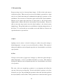
Before a processor can actually begin to play a video sequence, it has to pass through
eight stages. These stages are shown in figure 12 on the following page.
Unrealized
Configuring
Configured
Realizing
Started
Prefetched
Prefetching
Realized
Started
Stopped
Figure 14: Diagram showing the different stages of a processor
In order to prevent the processor object from progressing to the next state too early, a
wait for state method has been created. This method checks that the processor has
successful reached the current state (by a call to processor.getState() ). If it has, it is
allowed to progress to the next state, where as if it hasn’t it is blocked until it does so
(using the thread’s wait method). This method is extremely important because if a
processor progresses to any of the states too early, a malformed processor will be
created. The pseudo code for this method is shown below.
boolean waitForState(int state)
synchronized (waitSync)
while (processor.getState() != state && stateTransitionOK)
waitSync.wait()
return stateTransitionOK
55
5.2.4 Frame processing
In order to access individual frames of the video sequence, a codec has to been added
to the video sequence. This is done by firstly getting the TrackControls from the
processor and then setting the codec on the video track:
Codec codec[] = {
new PreAccesCodec()
new PostAccessCodec()
}
videoTrack.setCodecChain(codec)
This means that the codec's process methld will be the ‘callback’ whenever a video
frame goes through the plug-in. So for every frame in the video sequence, the
process method of the postAccessCodec will be called, with the current frame as a
parameter. postAccessCodec is a class nested inside the main class. It is based on
the example code provided by Sun Microsystems (see the reference section for a link
to this code). postAccess extends PreAccessCodec.
One of the requirements of the system was to single step through a video sequence for
analysis purposes (requirement 2.4.4(4)). In order to do this the automatic frame
processing which is carried out by the postAccessCodec has to be stopped. This is
done by using a Boolean variable called step.
The automatic frame processing
operations are then turned off. This happens when the user presses the pause button
(on the video control panel, below the input video sequence). The system is then
halted until either the forward frame, backward frame or play button is pressed. If the
play button is pressed the video sequence starts to play again, the Boolean variable
step is step to false and the segmentation process resumes. If either of the backward
frame or forward frame buttons are pressed, the current frame is replaced by the next
frame or the previous frame respectively and a method update is called. Update is a
56
method which updates the segmentation video, with the new segmented frame. (it
also updates all the user interface areas, with the correct motion property values).
No frame processing starts until a variable called detectColour is set to true. This is
set to true when the operator selects the colour of the object to be tracked (by clicking
on the object on the input video sequence). This process will be discussed in more
detail in the image processing operation
When the 5th frame is the current video sequence is passed through the accessFrame
method, a method grabFrame is called. This method passes the current frame into the
processImage object (by calling processImage.setBackground(image)). This image is
used if threshold background is turned on (this process will be explained in more
detail in the image processing section).
5.2.5 Image Processing
The processImage and componentLabelling classes make up the image processing
component which was described in the design section. The processImage class is
concerned with the segmentation of the image and the componentLabelling class
labels the image. Both of these classes will now be described in more detail.
5.2.5.1 ProcessImage
The first implementation issue is to do with the detectColour variable which was
mentioned in the frame processing section. This variable is set to true, when the
colour of the object to track has been selected. When the user clicks on the input
videoSequence, a method ( setColourPixel(int x, int y) ) is called in the processImage
object (from the main class) with a parameter of the co-ordinates which the user
clicked on. This pseudo code for this operation is shown on the following page
57
public void setColourPixel(int x, int y)
{
find the average red component of the 9 * 9 neighbourhood around the
selected pixel
find the average green component of the 9 * 9 neighbourhood around
the selected pixel
find the average blue component of the 9 * 9 neighbourhood around
the selected pixel
}
An average colour of the 9*9 neighbourhood surrounding the current pixel is used
instead of the actual colour value for the pixel clicked to give a more accurate result.
The red, green and blue components of the pixel are they stored as integer values, and
are used by the various image processing operations which are described later in this
section. The red, green and blue components are calculated by method calls to the
colour class. The colour class is a utility class which was written to perform some
colour calculations e.g. extracting the red, green and blue colour components from a
pixel and converting red, green and blue value to hue saturation and brightness
values.
Every pixel in this image is then looped through and the appropriate imaging
operations are called. The pseudo code for this process is given on the next page.
58
for every pixel Pij in currentFrame
red = colour.getRed(bufferedImage.getRGB(x,y));
green = colour.getGreen(bufferedImage.getRGB(x,y));
blue = colour.getBlue(bufferedImage.getRGB(x,y));
if (thresholdAverageOption == true && colourChoosen == true)
thresholdAverage(average, red, blue, green, x, y)
else if (thresholdBackgroundOption == true && colourChoosen == true)
thresholdBackground(red, blue, green, x, y)
else if (colourChoosen == true)
colourSegmentation(red, blue, green, x, y)
This differs slightly from the design, in that there is only one loop, with each
thresholding option called for every pixel in the loop. In the design section three
loops were used, one for each of the thresholding options. One loop is used instead of
three for efficiency purposes.
The red, blue and green components of the current pixel are passed into each of the
methods mentioned above. Since each of these methods where described in extensive
detail in the design section, another detailed description will not be given. One point
to note though, is that the red, green and blue pixel values which are passed into the
colourSegmentation method are converted to hue, saturation and brightness values.
This is so that they correspond to the hue, saturation and brightness sliders in the
image processing panel. The conversation of these values takes place in the colour
class and is a standard imaging operation.
The post processing operations, open and close are then applied to the frame (if they
are turned on, using the open and close buttons in the image processing control panel)
59
As mentioned in the design section the effectiveness of both post-processing
operations depends on the size of the mask which is used. Extensive testing was
carried out to find the optimum value for these masks. The larger the mask, the more
noise pixels are removed (however some valid pixels might be removed as well). For
the close operation it was found that a mask of between a 2*2 and a 3*3 proved the
most effective. A mask in between these values was created by using a 3*3 mask and
setting some of the bits to 0 so that they have no effect. The mask that was used for
the close operations is shown below;
010
111
010
A mask of 4*4 was used for the open operation.
The segmented frame is then returned to the main class, which calls the
componentLabelling object with a parameter of the segemented frame.
5.2.5.2 ComponentLabelling
The first task of the componentLabelling class is to label the image. The component
labelling algorithm is based on the code snippet supplied by Prof. Danny Crookes
(see appendix 5 for the original code). Because of this, and because the basic pseudo
code for this algorithm was described in the design section, no further explanation of
this algorithm will be given.
The area of each the two largest labelled objects is then found. This is done by
creating a histogram of the image i.e. the colour of each pixel is plotted against the
number of pixels that are this colour. This histogram is created as a 1D array. This
one 1D array is looped through and the largest two objects are found
60
The area of the two largest objects is then found. If the area of one hand is twice the
area of the other hand, the objects are said to be touching.
The objects are now labelled and must be correctly colour coded. It is extremely
important that the objects are coloured coded the same colour from frame to frame.
An example will be used to illustrate why this is so important. For the current frame,
the object on the left is labelled yellow, and the object on the right is labelled green.
Now on the next frame, the object on the left is labelled green and the object on the
right is labelled yellow. Even though the objects haven’t moved, the system will
think that the objects have swapped places and therefore the distance, direction and
speed motion properties will be worked out incorrectly. Therefore an algorithm has
to been made to predict the position of the objects.
The algorithm starts off by labelling the object on the left yellow and the object on the
right green. For every frame after this, the objects in the current frame are compared
with the position of the objects in the previous frame. They are coloured the same
colour as the closest object.
Now that a ranked list of objects has been extracted from the current frame, some
features can be extracted from each of these objects. This brings us onto the feature
extraction component.
5.2.6 Feature Extraction
Three motion properties need to be extracted from the current frame;
•
Centre co-ordinates in the horizontal (x) direction
•
Direction of motion
•
Speed
Each of these will now be discussed in more detail
61
5.2.6 Centre co-ordinates in the horizontal (x) direction
The first motion property has in fact already been worked out, in the component
labelling class. After this value has been calculated a passed into a hand object;
greenHand.setCentreX(greenX)
yellowHand.setCentreX(yellowX)
The hand class is responsible for holding data about each of the hands. Two instances
of the hand class are created, one for the green hand and one for the yellow hand.
As mentioned in the previous before, the centre co-ordinates (in the x direction) are
inputted to this class from the componentLabelling class. These values are stored in a
1D array using a circular bounded buffer approach. This is shown in figure 15 below
Take this
value (head)
Add new
element
here (tail)
Figure 15: Diagram showing how the centre co-ordinates are stored in an array
62
It was decided to store the values in this way for a number of different reasons.
Firstly so that the distance the hands have moved can be worked out over any number
of frames (up to the size of the buffer). This proved very useful for experimental
purposes and was helpful when finding the optimum number of frames to take the
distance over (it was decided to take the distance over the last two frames). It also
means that the system can be easily updated at a later stage e.g. the system can easily
changed to find the distance/speed that the hands had moved over n number of
frames.
When a call is made to setCentreX(int x) the integer value of x is added to the tail of
the buffer;
bufferX[tailX] = x
tailX = (tailX+1)%size
A element can be taken from the buffer by calling getCentreX(). This method always
returns the element at the head of the buffer. This method is implanted in such a way
that successive calls to this method will keep returning the latest value added, until a
new value is added to the buffer. This ensures that the right value is always returned.
5.2.6.2 Speed
The speed for each hand is worked out between the previous frame and the current
frame. It is also worked out in the hand class. It is worked out by taking the distance
moved over the last couple of frames and dividing this distance by two.
5.2.6.3 Direction
The direction is also worked out in the hand class. A detailed algorithm for this was
given in the design section (see section 2.3.2.6) and therefore there is no need to
going into any further detail.
63
Now that these motion properties have been worked out they can been displayed in
the information area. The updateTextFields method extracts the motion properties
(distance, direction) from the current frame by calling appropriate methods in the
hand class.
Using these motion properties the current motion can be interpreted. This brings us
onto the next section.
5.3.7 Motion interpretation
Most of the motion interpretation is carried out by the motion interpretation class.
The class is called by the main class and the Boolean values which are returned from
the method calls determine what icons are displayed in the information area. The
algorithms determining the motion interpretation was discussed in the design section
and so don’t need to be mentioned again.
The component Labelling class is responsible for working out if the hands are
touching. Using this information, it can be worked out when the hands actually clap.
The hands are only ‘clapping’ the first frame of when they are touching. So a
Boolean variable is set to false, after the hands touch for the first time and remains
false until the hands start to move apart again. This ensures that the hands are only
classified as clapping once during one ‘clap’.
Every time that a clap occurs, the current time is recorded, this time is subtracted
from the previous time to give the time between claps. This value is compared with
the time between beats variable and then the according child feedback is displayed.
64
5.3.8 Playback of Music
Midi files are used as the audio sequence, as opposed to wav files or mp3s. This
decision was taken for a number of reasons;
•
A large number of midi files are freely available
•
Information about a midi file (e.g. current tempo) is easily obtainable
•
Midi files can be easily created and so if the operator wishes they can
compose their own audio tracks
In order to play a midi sequence, a sequencer has to be created and a midi file is
played through the sequencer.
sequencer = MidiSystem.getSequencer()
sequencer.open()
sequencer.setSequence(MidiSystem.getSequence(midiFile))
sequencer.start()
The tempo of the music is then recorded and using this the time between beats is
worked out. The time between beats is compared with the time between the claps and
is used to produce the child feedback.
timeBetweenBeats = 60/(sequencer.getTempoInBPM())
5.3.9 Feedback Generation
Feedback generation is calculated by comparing the timeBetweenBeats variable
(which was calculated in the last section) and the time between claps.
65
5.3.10 Child Feedback
The feedback discussed in the last section is presented to the child in the form of a
face (this was discussed in detail in section 4.1.2)
5.3.11 Utility Classes
These are classes which do not directly correspond to any of the components
mentioned in the design but perform mandatory functions.
MovieFilter
MovieFilter is a small utility class which extends FileFilter. It is responsible for
making sure that the video file that the user tries to open is of type avi or mpeg.
Colour
Colour is a utility class which contains various coloured related methods which are
not part of the java imaging library. They were grouped together in one class for
code reusability purposes.
66
6. Testing
There were two types of testing carried out on the system. White box testing and
black box testing, these are outlined in more detail in the sections below.
6.1 White box testing
White box testing was carried out during the development of the system using test
harnesses. These test harnesses were used to test individual classes before there were
integrated with the main system. A good example of this is the hand class. Before it
was integrated, tests were carried out to make sure that correct value was being pulled
out of the array. Some of these tests are shown below;
hand1.setCentreX(10);
hand1.setCentreX(10);
hand1.setCentreX(1);
hand1.setCentreX(2);
System.out.println(hand1.getCentreX());
System.out.println(hand1.getCentreX());
System.out.println(hand1.getCentreX());
System.out.println(hand1.getCentreX());
White box testing proved invaluable for this system, as prevented major problems
when adding new classes to the system.
6.2 Black box testing
Black box testing involved using the system and making sure it operated correctly.
Black box testing was carried out during the development of the system, to make sure
that the core functions didn’t break when new elements were added to the system.
67
Exhaustive black box testing was also carried out when the development of the
system was finished. These tests were carried by volunteers who had no knowledge
of the internal workings of the system. As well as testing the functionality of the
system these tests provided feedback on how to make the user interface more
friendly.
Some examples black box tests are shown in the below table 2 below.
Test Case
Description of test
case
Expected
behaviour
Result
Change input to
input from a web
camera when no
web camera is
connected
Make sure a web
camera is not
connected to the
computer. From
the input menu
select web camera.
A error message
should be
displayed.
Pass
Click on an object
to track
Click on an area of
the input video
sequence
The segmentation
process should be
started
Pass
Change the audio
tempo
Using the audio
slider, change the
tempo of the audio
sequence
The tempo of the
Pass
audio sequence
should changed to
the new tempo
selected by the user
Change the audio
track
From the audio
menu, select a new
audio sequence to
play
The currently
playing audio
sequence should
stop playing and
the selected audio
sequence should
begin to play.
Pass
Table 2: Examples of the type of test cases which were performed on the system
6.2 Test conclusions
The extensive testing which was carried has made the system extremely robust and
reliable.
68
7. Conclusion
7.1 Evaluation
The system is well designed, robust and fulfils all the requirements (including the
optional ones) which were set out in section two. The user interface is easy to use
and all of the test subjects were able to use the system with little or no prompting.
Unfortunately due to time constraints, the system tested on children therefore no
comments can be made on how effective the child feedback was.
7.2 Findings
A number of findings have come out of the system. The first major finding is to do
with the segmentation process. A number of optional operations are built into the
system to improve the quality of the segmentation (e.g. threshold background). It was
found however, that in the majority of cases these options do not need to be used.
They only need to be used in difficult lighting conditions.
The system runs in real time, when none of the segmentation options are turned on.
However when either, or both of the post processing operations (open and close) are
turned on the system slows down quite significantly. Therefore there is little or no
point using these operations when running the program live from a web camera.
The threshold average didn’t perform as well as expected. This function works on the
principle that the background will be a brighter colour than the objects which are to
be tracked. However there are problems with using a light colour as a background.
which can cause reflections. These reflections, when captured by a web camera can
turn into a multitude of colours (usually yellow, but sometimes blue or red). If the
gloves are the same colour as these reflections, the program might classify the
reflections as hand objects.
Therefore it is better to use a darker colour as a
background and by doing this threshold average will not work.
69
Out of all the optional processes to improve the segmentation process, threshold
background was found to be the most valuable. It successfully enhances the quality
of the segmentation, especially when the background is of a similar colour to the
colour which is being tracked.
7.2 Future Enhancements
Due to the research nature of this project, there are a large number of enhancements
which could be made to this system. A few of these have been outlined below.
The equipment used was very low budget. If more expensive, high quality web
camera was used the results of tracking the hands could be improved. At the moment
if the child were to move his hand very fast across the screen, they would just appear
as flashes and the system would not be able to correctly interpret what is happening.
The interpretation of motion could be improved on. At the moment it is decided if
the child is clapping by examining the area of the hands and the previous x coordinates. While this is a good way to classify the motion, the system can be fooled if
the child moves one hand behind another. One way of potentially stopping this from
happening is to examine the angle of the hands. Just before the child claps both
hands should be vertically straight. If however the hands miss and one hand passes
behind the other, you would expect both hands to be slightly angled towards the
ground. Another way to determine if the child claps or the hands simply cross path is
to use two web cameras so that a 3D image can be built up. One web camera would
look down on the child and the other would be face on.
The system could create a log of how well a child is clapping in time with the audio
sequence. Over a period of time this log could be reviewed and improvements could
be easily spotted.
70
7.3 Summary
In summary this project has been a success. A system has been created which can
accurately track and interpret a child’s movements using low budget hardware. The
project was not meant to address and solve all the issues in this area, but rather to
open people’s eyes to the possibility that computer systems can be used to aid child
development.
71
References
Image processing resources
Image Processing Learning resources:
http://homepages.inf.ed.ac.uk/rbf/HIPR2/hipr_top.htm
Programming in Java Advanced Imaging (Sun Microsystems):
http://java.sun.com/products/java-media/jai/forDevelopers/jai1_0_1guideunc/JAITOC.fm.html
Learning java 2D (Sun Microsystems):
http://java.sun.com/developer/technicalArticles/GUI/java2d/java2dpart2.html
Wayne, N., 1986. An Introduction to Digital Image Processing, UK: Prentice/Hall
International.
Efford, N., 2000. Digital Image Processing: a practical introduction using Java,
England: Addison-Wesley.
Java Media Framework Resources
JMF API Specification and JMF API guide:
http://java.sun.com/products/java-media/jmf/2.1.1/specdownload.html
JMF Programmers guide:
http://java.sun.com/products/java-media/jmf/1.0/guide/index.html
JMF forum:
http://forum.java.sun.com/forum.jspa?forumID=28
Frame Access Demo code
http://java.sun.com/products/java-media/jmf/2.1.1/solutions/FrameAccess.html
72
Article about Conquering Swing deficiencies in MDI development:
http://www.javaworld.com/jw-05-2001/mdi/jw-0525-mdi.zip
Source code for MDIDesktop
http://www.javaworld.com/jw-05-2001/mdi/jw-0525-mdi.zip
Java Sound Resources
Java Sound API:
http://java.sun.com/products/java-media/sound/
Java Sound Resources:
http://www.jsresources.org/
73
APPENDICES
The appendices contain information that is not appropriate to be included within the
main body of the dissertation but is required for assessment. Below is a list of each of
the appendices.
Appendix 1
Project Problem Description
Appendix 2
The source code for the project is quite extensive and as a result it is not going to be
included in the appendix. Instead it is included on the attached cd – see appendix 5.
Appendix 3
An installation guide and user manual
Appendix 4
Examples of inputs and the corresponding output from the system
Appendix 5
The component labelling source code supplied by Prof. Danny Crookes.
Appendix 6
Contained on the source disk is the complete program source code
Appendix 7
The signed project minute forms
74