1
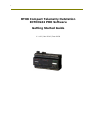
1
RTU8 Compact Telemetry Outstation
IOTOOL32 PRO Software
Getting Started Guide
V. 1.00 / Nov 2010 / Doc 40031
2
1. Introduction
The RTU8 range of Compact Telemetry Outstations provide an efficient and cost effective
means of monitoring remote/unmanned plant and logging valuable data for later analysis.
The RTU8 can use a variety of communications medium from single serial links through multidrop, public or private telephone systems, GSM cellular systems and radio links.
The RTU8 hardware is only halve the system though. The complete system includes the
IOTOOL32 PRO suite of PC software and for efficient operation both the hardware and the
software must be configured correctly. As with most things configuring both is relatively
easy, once you know how.
This Getting Started Guide will give you an easy learning curve. It should be used in
conjunction with the full User Manuals.
2. RTU8 Hardware
Details of how to install an RTU8, connect the supply, inputs and outputs etc. are described in
detail in the RTU8 User Manual. We shall not repeat them in this guide, except for the points
it is essential you understand and which experience has taught are the things people can get
wrong.
The RS232 Serial Port/s
The RTU8 has one or more serial ports for communicating with the PC, other RTUs etc. The
primary port (port A) in on the top of the unit, being a 9 pin sub-D connector and it is this
port that we shall talk about in this guide. See separate documentation for details of using
port B.
You should be aware of two terms, which are used extensively in Data Communications, DTE
(Data Terminal Equipment) and DCE (Data Communications Equipment).
The RTU8 is a DTE and normally PCs, industrial controllers etc. are also DTEs. Modems are
normally DCEs.
When you connect a DTE (RTU8) to a DCE (modem) you must use a V24 modem/serial cable
which connects the TX pin on the DTE to the TX pin on the DCE and likewise connects the RX
pin on the DTE to the RX pin on the DCE. A straight through connection. This apparent
mistake of connecting a Transmitter (TX) to another TX, can be explained in that one of the
pins marked TX is in fact a Receiver RX. They are just labelled TX, meaning that they join
one to another.
When, however, you connect a DTE (RTU8) to another DTE (PC) you must use a Null Modem
Cable, which connects TX to RX. It has a crossover.
If your RTU8 will not talk to your modem/PC, please check you are using the correct
cable. It is an easy to use the wrong cable!
3
Thus when you connect your RTU8 to a PC for configuration, use will use a Null Modem Cable
(available from Brodersen) and when you connect the RTU8 to a modem you will use a
different (modem) cable.
The DIL Switches
On the top of the RTU8 there is a bank of 10 DIL switches, just to the right of the serial port.
It is essential that these switches are set correctly. If you have a problem with your
RTU8, check the position of these DIL switches.
The DIL switches are used to set the address of the module, the baud rate at which the RTU8
should communicate and to switch between dial-up and serial mode.
The DIL switches are in the OFF position when they are towards the front of the RTU8 and are
in the ON position when set towards the back of the RTU8, nearest to the DIN rail. Switch 1
is on the left, looking from the front.
Working from left to right, from the front of the RTU8:
The first 5 DIL switches are used to set the address of the RTU8 in binary form, thus:
Switch 1
Switch 2
Switch 3
Switch 4
Switch 5
ON
OFF
OFF
OFF
OFF
= address 1
OFF
ON
OFF
OFF
OFF
= address 2
ON
ON
OFF
OFF
OFF
= address 3
OFF
OFF
ON
OFF
OFF
= address 4
ON
OFF
ON
OFF
OFF
= address 5
etc.
The next 3 switches set the baud rate, at which speed the RTU8 will communicate. This can
be set from 300 to 9,600 baud. Unless you have a very good reason for setting it otherwise,
you are recommended to use the maximum speed of 9,600 baud (software default speed).
For this speed (9,600) switches 6,7 and 8 are set:
Switch 6
Switch 7
Switch 8
On
OFF
ON
= 9,600 baud
See RTU8 User Guide for other settings.
4
Switch 9 is used to set the RTU8 in dial-up, Modem mode (with Hayes commands) or in Non
Modem mode (no dial-up, permanently connected).
Switch 9
Off = Non Modem mode
On = Modem Mode
Switch 10
Is not used, but should be always be in the ON position.
Please note that these DIL switches are only read by the firmware at power on. If you make
changes to the DIL switch settings, the changes will not be implemented until you power
down (count to 10) and reapply the power.
LEDs
Depending on the specific type of RTU8 that you have, the LEDS on the front will give you
valuable indicate of the RTU8s status. Not all RTU8s have all of the following LEDs:
Power LED
Off = No supply voltage
On = Supply voltage OK
And when fitted with stand-by battery
Flashing (longer off than on) = No supply voltage, running on battery
Flashing (longer on than off) = Supply voltage OK, battery low/fault
System LED
Off = No task (B-Con or A-Ware) running in the module.
On = OK
This LED also gives power indication for RTU8s without a Power LED, see USER Guide. If OFF
check that a task has been downloaded into RTU8 and that it has been started. It is a
common fault to download a B-Con task and not start it running. A-Ware will automatically
start a task.
5
I/O LED
Off = Fault with I/O
Flashing = I/O configuration error
ON = I/O including any expansion modules OK
If you add/remove an expansion module, you must power down (count to 10) and reapply the
power, so that the RTU8 can automatically re-configure itself. In such case you will also have
to rescan the RTU8 from the PC, see below.
If all three of these LEDs are not lit, there is a problem that you should investigate,
but don’t panic if the RTU8 is new and the System LED is not lit, see below.
RX/TX Leds
On = data being received and/or transmitted through the serial port.
Note that these LEDs are connected to port A and not Port B (when fitted).
The RTU8/expansion modules may also have LEDs on the I/O:
Digital Inputs/Outputs
Off = low (logic false)
On = high (logic true)
Analogue Inputs
On = Input being scanned
So now having set up your RTU8 correctly, ensuring that the correct serial cable is being
used, the DIL switches are set correctly and that the Power and I/O Leds are Lit (don’t worry
about the Systems LED if this is a first time configuration), we can proceed to look at the
software.
IOTOOL32 PRO
IOTOOL32 PRO is a suite of Windows based PC software used with the RTU8.
It consists of:
IOExplorer – A useful commissioning and fault finding tool.
RTU8 Log – A utility programme for uploading log files from the RTU8 to disk.
B-Con – An IEC1131 Instruction List programming tool.
A-Ware – A menu driven, simple to use, version of B-Con.
DDE/DLL – Used to connected third party application software.
6
Principle of Operation
It is most useful to understand the principle of the system, this makes the different parts of
the software more understandable.
The system revolves around a dynamic database, housed in the PC memory. This database is
created when the PC scans an RTU8 and it is dynamic, meaning that its size will automatically
be adjusted to the configuration and number of the RTUs in use.
When an RTU is connected to the PC, either permanently or via a dial-up connection, the PC
software will read the status of the RTU8 inputs and place them in the database. It will
likewise read the status of outputs in the database and write these values to the RTU8. This
happens automatically, as a background task, over which you have no control.
Thus all read and write tasks to the RTU8 hardware are handling by the software without any
input from user, but the user can, of course, read this data and in the case of outputs, set a
value.
Application software (runtime operator interfaces), such as A-Ware, Excel spreadsheets,
SCADA etc. can access this database, read inputs and set outputs, via specific drivers or using
the DDE and DLL supplied with IOTOOL32 PRO.
This makes the system very quick to get up and running. For instance, an Excel spreadsheet
can be configured to monitor an RTU8 in minutes, see below.
The I/O status written to or read from the database are, however, only the real time values.
Logged or historical data is stored within a non-volatile buffer in the RTU8. This data is
uploaded to the PC by the RTU8 Log utility and does not involve the database.
Lets look at each part individually:
IOExplorer
This piece of software really is a useful tool. Its importance cannot be overstated. It is a
window through which you can access the dynamic database. When commissioning a new
RTU8 or trying to solve a problem IOExplorer will help you.
IOExplorer has a layout similar to Windows Explorer, except that on the left of the screen,
instead of seeing your hard disks and their directories, you will see the RTU8s in your system.
You will actually see Netx and under it Node 1.
This needs to be explained. The Net number (x) is the address you set on the RTU8 DIL
switches. When using RTU8s in dial-up mode you will only ever have Node 1, if you use
multi-drop you could also have Node 1, Node 2 etc., but we shall here, assume that you are
using a dial-up system. Therefore an RTU8 with the address 1 will be shown as Net1 – Node
1, address 2 as Net 2 – Node 1, address 3 as Net 3 – Node 1 etc.
Now again like Windows explorer if you highlight the Node 1, under the relative Net, on the
right of the screen will appear information relative to that Node or RTU8, but if you are
starting from scratch then you will not see any Net or Nodes. You will need to Scan the RTU8.
7
Scanning a RTU8
A RTU8 needs to be scanned so that the PC software knows of its existence and its
configuration. The RTU8 has, within its non-volatile memory, a lot of configuration
information, some installed in the factory, such as it I/O count, memory addresses etc. and
some installed by you, as we shall see shortly.
Scanning an RTU8 is easy. Connect your RTU8 to the PC with a Null Modem cable. Install
IOTOOL32 PRO, as described in the IOTOOL32 PRO manual and start IOExplorer from the
Icon on your desktop.
Now still using the IOTOOL32 PRO manual, start and name a new project and scan the RTU8,
being careful to insert in the pop-up box the correct address of the RTU8, if other than 1, and
the select the correct PC com port (to which the RTU8 is connected), default is com 2. Don’t
change anything else, sit back and watch the progress of the scan. It will take approx. 45 –
60 secs.
After the scan has been completed you will see, at the bottom of the screen, the system Log.
This is a very important tool. If you can’t see it, tick to view, in the System Log Menu.
The System log tells you what is happening with regard to communications to the RTU8/s. If
you have a communication problem look in this file, 99 times out of a 100 it will point you in
the direction of a solution. For now it will probably look something like this:
01/29 10:02:37.890 Opening project file: C:\Drivers \Project1.INI
01/29 10:02:37.940 Loading MBUS32L.IOD driver
01/29 10:02:37.940 System 2000 Null Modem I/O Driver (MBUS32L.IOD), V2.30, loading
01/29 10:02:37.940 Copyright (c) 1996,2000, Brodersen Controls A/S, Denmark
01/29 10:02:37.940 Net1WinRtsControl RTS control=-1
01/29 10:02:38.160 MBUS32L.IOD is using COM1 at 9600,N,8,1
01/29 10:02:46.070 I/O database size is 2846 bytes. (Max 100000 bytes)
01/29 10:02:46.070 Project initialized
01/29 10:02:46.070 Starting I/O scan on COM1 for Net 1
01/29 10:02:46.180 COM1, is now online
The last line is the important bit; COM1 is now online. Thus everything is OK.
On the left of the screen you will see Icons for Net 1, Node 1. Click on Node 1 and on the
right four tabs will appear I/O, Net Info, Config and B-Con.
8
I/O Tab
This is your window to view the system database. It shows you the values of inputs and
outputs. It is your commissioning tool. Test the system by driving the inputs on the RTU8
and watch the values appear on the screen. Remember the values are shown in words so
that driving DI 0 will produce the value 1, DI 1 the value 2 and both together the value 3 etc.
If you can’t see the inputs, it is probable that a B-Con or A-Ware programme has not been
yet downloaded into the RTU8. Once a programme, with define statements (see the
IOTOOL32 Pro Manual), has been downloaded you will need to rescan the RTU8. You will
then see the inputs. You can also set outputs from this screen.
The box marked ST is a status word. It should have a value of 0. Any other value indicates a
problem (red crosses will also appear by the Net/Node Icons), see the table below:
ST Value Meaning
0
OK
1
Slave time-out
8
B-CON programme stopped
16
Error serial port
32
Error serial port
48
Error serial port
128
Mains or battery low
2050
Error local bus
4096
Deviation output configuration
16464-6
Scan time error (B-CON)
32897
Communication error
32904
Password not correct
32912
Deviation input configuration
37168
Communication error
Beware if there is more than one fault the values are added together, thus a Slave time-out
and B-Con programme stopped will return a value of 9 (1 +8).
Net Info Tab
This screen gives you information about the RTU8.
9
Config Tab
This screen allows you to configure parameters within the RTU8. Please understand that
values entered here are downloaded to and used by the RTU8, not the PC. They are:
PLC TX and RX
Ignore these and do not change.
Logical Address
Is used in conjunction with the DIL switch to define the address of the RTU8. The value
entered here will be added to the DIL Switch value to get a total address.
Retry Count
Defines the number of times the RTU8 will redial a number, if the first attempt is
unsuccessful. If set to its default of 3, the RTU8 will dial 4 times (initial call plus 3 redials)
before giving up.
MaxComCount
The Com Counter defines the number of times the inputs/outputs will be read/written, up to
255, before the RTU8 makes a hang-up. The Default value is 256 and with this value an
automatic hang-up will not be made by the RTU8. Provided the RTU8 is connecting to a PC
there is no need to change this value, as the PC will terminate the connection, via the PC Com
Counter and the RTU8 will see the lost of carrier and then automatically make a hang-up
signal to the modem. This way the PC Log Upload utility can override the PC Com Counter
and hence the termination of the connection, until the log files have been uploaded.
Subs. to Try
Defines the number of other telephone numbers to call, if all previous attempts to reach a
given number have failed.
Redial delay
Sets the number of seconds delay between a failed dial-up and the next re-dial. Leave it at
its default of 90 secs.
Telephone No.
List of 50 telephone numbers the module can dial, identified as number 0 – 49 (Some older
RTU8s only have 10). Enter the numbers you wish the RTU8 to dial.
10
Modem Init
The initialisation string the RTU8 should give the modem connected to port A. When using a
Brodersen modem, do not change, but if using a third party modem refer to the modems’
handbook for the correct string.
Date/Time
Here you can synchronise the Real Time Clock time in the RTU8 to the PC clock, but check
your PC time is correct.
Table 101 – 103
Linearisation table data for RTD and thermocouple expansion modules. See IOTOOL32 Pro
Manual for further information.
Password
Allows you to select one of two levels of password protection and insert/change a password.
See IOTOOL32 Pro Manual for further information.
Log Buf Size
This allows you to specify what percentage of the 480K byte log buffer should be used.
Default is 100%.
SMS Tel. No
This is the number of the SMS message centre though which SMS messages are sent. Often
this number is not required and this field can be left blank. See SMS Getting Started Guide.
SMS Text
Here you can enter the text of the ten different SMS messages that can be sent by the RTU8,
when connected to a GSM modem. See SMS Getting Started Guide.
DI Counters
Here you can enable the first two digital inputs as firmware counters. Disabled, (default) they
act as normal digital inputs.
Double click on any of the above boxes, in the column marked Value, to make changes.
11
B-Con Tab
This screen informs you as to whether a B-Con/A-Ware programme is running in the RTU8
and allows you to start/stop/refresh same. You will probably never use it.
You only need to scan/rescan the RTU8 when:
The RTU8 is first connected to the project.
You change the RTU8 hardware configuration (add/remove I/O)
You change the RTU8 DIL switches.
You download a new B-Con programme, in which “Define” statements have been changed.
See the IOTOOL32 PRO manual.
Do not automatically try to rescan when you have a problem, instead solve communications
problem by looking in the System Log and test data transfer in IOExplorer.
Programming a RTU8
Having now scanned the RTU8, tested communications/data transfer and set the various
configuration values, you can now proceed to programme the RTU8 to your requirements.
See the B-Con or A-Ware Getting Started Guide and Manuals.
Changing to Dial-Up Mode
With programming the RTU8 complete and having rescanned the RTU8, if necessary (see
above), all that now remains is to install the RTU8 at its remote location and switch both the
RTU8 and PC (with respect to that RTU8) to dial-up mode.
To switch the RTU8 to dial-up mode all you have to do is connect it to the modem and change
DIL switch 9 to the ON (towards the back of the RTU8) position. Please remember that you
must power down and back up to make changes to the DIL switches effective. Remember
also to use a modem cable, not the Null Modem cable you used to connect to the PC.
The PC also needs a change, made in IOExplorer. Simply select the relevant Net/Node and
hit the Rescan Button. The pop-up box will appear again. In the Driver section select Modbus
Modem, in place of Modbus Null Modem. A new pop-up box will appear in which you need to
insert the telephone number of the RTU8 and define the PC modem to be used when
connecting to the RTU8. See the IOTOOL32 Pro Manual. Once done hit the scan button and
the PC will dial the RTU8 and rescan it.
After the rescan you will see three new buttons on the menu bar; Dial, Hang-up and Online,
which can be explained thus:
Dial – Manually instigate a dial-up. (Select Net/Node first) to the RTU8.
Hang-up – Manually hang up. RTU8 or PC will automatically do this anyway.
Online – Overrides the automatic hang-up and forces the RTU8 to remain on line. Be careful
with this button, you could get a large phone bill if you use this facility and forget to cancel it
or perform a manual hang-up.
12
You can now further test the system by dialling up the RTU8 and reading I/O status.
IOExplorer has other features, please see the IOTOOL32 Pro Manual for full details.
RTU8 Log
This utility programme for uploading log files from the RTU8 to disk can be started from the
button, on the left and just below the menu bar in IOExplorer.
Full details of how to use this utility are given in the IOTOOL32 Pro Manual, but please note
the following points:
The data in the log files, is that which you, by way of your B-Con/A-Ware programme, have
instructed to RTU8 to store in up to 32 different log files. Only data specified will be logged.
When the data is uploaded into the PC, it is written to the hard disk as a comma separated
ASCII file. This type of file can easily be loaded into a spreadsheet, or other software, for
analysis. An example of an Excel spreadsheet in provided on the IOTOOL32 PRO CD,
together with a manual for its use.
If you select the Auto-Mode feature, meaning that the log files will automatically be uploaded
every time the PC is in contact with the RTU8, then it is the best that the Com Count, in the
RTU8, is set to 256. If set to a lower value Auto-Mode may not have enough time to upload
the log files before an automatic hang-up is made by the RTU8. You must also run the utility
continuously, but it can be on the task bar.
B-Con and A-Ware
These programming tools can also be started from buttons below the menu bar. Please see
the B-Con and A-Ware Getting Started Guides/User Manuals for detail of how to use them.
DDE-Server (Dynamic Data Exchange)
This is another utility that Windows can use to connect third party application software to the
IOTOOL32 PRO dynamic database. This software could be a SCADA package, spreadsheet,
Visual Basic Programme etc.
See the IOTOOL32 Pro Manual for full details of its use.
You do not need to use the DDE when using the Brodersen/Zenon SCADA package. This
package is fully integrated into the system, with fast, dedicated drivers and compatible log
data format.
We hope this guide has been successful in helping you to use an RTU8 and IOTOOL32 PRO for
the first time.