1
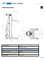
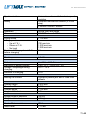
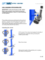
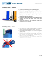
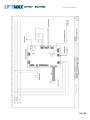
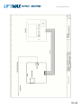
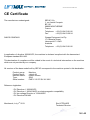
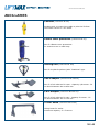
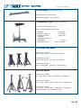
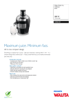
AUS - Wireless Users Guide v0.doc USER’S AND MAINTENANCE GUIDE Wireless BL-75EW DATE (1) COLUMNS # (1) (1) Would you please fill in these sections 1 / 40 AUS - Wireless Users Guide v0.doc 2 / 40 AUS - Wireless Users Guide v0.doc CONTENTS Important information Specification Unloading procedure Safety instructions Graphic symbols page 5 page 6 page 8 page 10 page 10 Lifting procedure page 11 Keyboard How to navigate into the menu Maintenance menu page 15 page 16 page 20 Fault code table Maintenance page 22 page 23 List of parts (mechanical) List of parts (electrical) Electrical diagram page 24 page 28 page 32 CE certificate Warranty Ancillaries Contact us page 36 page 37 page 38 page 40 3 / 40 AUS - Wireless Users Guide v0.doc 4 / 40 AUS - Wireless Users Guide v0.doc IMPORTANT INFORMATION This manual must be considered as an integral part of the equipment and must be read before using the equipment. Therefore do not lose it and keep it in good condition. Read carefully all the safety instructions contained in this manual as well as the safety labels applied on the columns. Maintain these labels in good condition and replace any label that become loose or damaged. Learn how to use your equipment correctly. Do not let anyone else use it without prior instruction. Maintain your equipment in good working order. Unauthorised modifications are forbidden. They may shorten its working life and immediately terminate the guarantee. Static and dynamic tests are carried out according to the EN 1493 standard: - Static test: overload 50% - duration of application: 1 hour; - Dynamic test: overload 15% - 3 lifting cycles; - Operating tests; - Measurement of load intensities; - Safety tests. 5 / 40 AUS - Wireless Users Guide v0.doc SPECIFICATION Lifting capacity Number of column 7.5 t 1 to 8 (the columns are the same – no master or slave) Tyre size Length of the fork Distance between the front of the chassis and the rear of the fork Lifting height Diameter from 600 to 1,155 mm 345 mm 195 mm 1,835 mm 6 / 40 AUS - Wireless Users Guide v0.doc Synchronisation Safety Automatic and smooth thanks to speed variation Patented mechanical ratched (2.5 mm step) « column moved » sensor Operation Communication Group, pair and single SWiP Wireless 2.4 GHz Lifting stroke Lifting speeds - Up at 7.5 t - Down at 7.5 t - No load Number of lifting cycles at 7.5 t before charging 1 750 mm 790 mm/min 1,300 mm/min 1,090 mm/min 18 Electric power 1,8 kW Batteries Electronic 3-phase charger Voltage / Amperage during charging Duration of charging 2 x 12 V – 100 Ah in serie 230/110 V – 50/60 Hz – 3A 24 V – 10 A 10 h Moving the column Hydraulic palette jack and 2 fixed front wheels Overall height Overall width Overall length Height of the foot 2,520 mm 1,055 mm 1,165 mm 135 mm Weight without batteries Weight with batteries 350 kg 400 kg Duster Water resistance Noise level IP54 < 70 dB 7 / 40 AUS - Wireless Users Guide v0.doc UNLOADING PROCEDURE IMPORTANT: Leave the straps on the "pallet lifter" type hydraulic tow handle during all handling operations: there is a risk of pulling out the piston. The mobile columns are delivered in the vertical position. Remove the fastenings and make sure that the capacity of your unloading system is at least 500 kg. Handling operations must be carried out slowly and without any shocks Unloading the column Lift the rear of the column by keeping the handle of the palette jack upwards and by pumping the handle up and down Move the column Release the handle of the palette jack to replace the column on the ground 8 / 40 AUS - Wireless Users Guide v0.doc Unloading using a forklifter Take the columns to the unloading point, Raise the rear of the column off the floor using its pallet lifter handle Slide the fork-lift forks under the column's base Gently raise the fork and strap the column base onto the fork lift forks Smoothly lower the column to the ground and remove the fork lift forks from under the column, Move the column to the side and repeat the operation for the others. Unloading using a crane Use slings in good condition and of suitable length (Nylon slings are perfectly suitable), Only attach the slings to the column using the lifting rings, Gently carry out the manoeuvres and lower the column to the ground, making sure to lower it in the vertical position, Move the column to the side and repeat the operation for the others. 9 / 40 AUS - Wireless Users Guide v0.doc SAFETY INSTRUCTIONS Concerning the user LIFTMAX lift users should not use their equipment for any purpose other than those specified. Make sure that nobody stands under, inside, or on the vehicle, while it is being lifted. LIFTMAX mobile lifts should not be used for access to the lifted vehicle or to reach mechanical components/assemblies. Keep feet, hands, or any clothes away from moving components. Prior to carrying out a maintenance work, make sure that power to the equipment is turned OFF. Concerning the lifting hoist Do not overload LIFTMAX lifts. Do not bypass or short-circuit any safety components. Do not reverse phase sequences inside motors or electrical panels. Repair your equipment as soon as a breakdown occurs. Do not use LIFTMAX lifts to move the vehicle horizontally. Do not drive over cables and plugs. Do not connect more than 6 columns together. Do not use lifts with different lifting capacities and speeds as a set without consulting our engineers. Do not pull control cables in order to disconnect columns. Do not open electrical panels without the authorization of supervisors or shop foremen. Do not modify electrical boxes. Do not store or put anything inside the electrical panels. Do not expose LIFTMAX lifts to water, rain, sandblasting, paint or explosion prone environments. Do not forget to lower the base of the column by means of the jack at the rear when the lift is stored. Do not forget to lower the base of the column and free the rear castor wheel that should not bear any load. LIFTMAX lifts should be stored in a standing position. Use the tow bar to move columns around the load. Each column must rest on the floor. Assure that power plug has sufficient amperage and voltage to support electrical requirements of lifts. Position the lifts around the vehicle in the configuration shown in the diagram on the lift column. Raising the vehicle Do not start engine while the vehicle is raised. Release the vehicle brake before lifting vehicle. Do not raise any vehicle higher than 50cm (19”5/8) from floor level by individual or paired operation. Do not use any accessory that is not manufactured by LIFTMAX. Use only LIFTMAX stands Load shall be equally distributed when using the lifts. Centre wheel between forks. Make sure that load is properly secured and that the lifting points of the load are in good condition and enough resistant. Check connections between columns. Check the size of the tyre to make sure it fits the carriage. Make sure that tyres are properly inflated. Use synchronous operation mode for lifting the entire vehicle. The environment LIFTMAX lifts must not be used if floor grading exceeds 2%. The lifts must not be displaced by means of the drawbar if the floor grading exceeds 2%. The lifts must not be stored on a floor whose slope exceeds 2%. Use a support plate, if the ground resistance is lower than 3400 psi. Use the lift on a horizontal plane surface. Make sure that there is no obstacle under the forks and over the vehicle to be lifted. Make sure that no obstacle interferes during the column displacement. GRAPHIC SYMBOLS Trained users only Warning Wheels free Watch Electrical hazard 10 / 40 AUS - Wireless Users Guide v0.doc LIFTING PROCEDURE Moving the column Lift the rear of the column by keeping the handle of the palette jack upwards and by pumping the handle up and down Move the column Release the handle of the palette jack to replace the column on the ground Placing the lifting fork under the tyre Fully engage the fork of each column under the tyres of the vehicle Centre the column to the tyres Check that the vehicle’s wheels are moving freely Setting the screen contrast You can change the main screen contrast / at all times by pressing the buttons located beneath the screen. 11 / 40 AUS - Wireless Users Guide v0.doc Set up a lift Column 1 Switch on the first column by turning the red battery switch The screen shows the self diagnosis The column is waiting for the magnetic RFID card. Place the card to front of the RFID sign (no contact is needed). Number 1 is blinking on the screen. This is the first column of the lift 12 / 40 AUS - Wireless Users Guide v0.doc Column 2 Switch on the second column by turning the red battery switch The screen shows the self diagnosis The column is waiting for the magnetic RFID card. Place the card to front of the RFID sign (no contact is needed). Number 2 is blinking on the screen: The second column knows that there is already one column activated for this lift thank to the unique code inside the RFID card. 13 / 40 AUS - Wireless Users Guide v0.doc Adding columns up to number 8 and closing the lift To add other columns, proceed to steps 6 to 10. To close the lift, place once again the RFID card in from of 1 column of the lift you just setup. (example shows the column 2) Then you have a visual confirmation on the screen that the lift configuration is done. The screen shows then the main page. The lift is ready. To lift a vehicle, plug the remote on one of the column of the lift and the press the up push button. To stop the operation, just release the button. At any time, you can select the pair or single mode by entering in the menu. You can also change the lifting speed or the lifting height (see here after). 14 / 40 AUS - Wireless Users Guide v0.doc KEYBOARD « Power on » white led « ENTER » button « in default » red led « UP » and « DOWN » button RFID reception area 15 / 40 AUS - Wireless Users Guide v0.doc HOW TO NAVIGATE INTO THE MENU Navigation buttons Menu tree Group mode Single mode Pair mode Automatic speed (adjusted to the load) Slow lifting speed (300 mm/min) 16 / 40 AUS - Wireless Users Guide v0.doc INFORMATION Date of control of the bronze nut (non applicable for the wireless version) Date of greasing of the lifting nut Date of the next inspection Date of commissioning PLC software number HMI software number Serial column number HMI card serial number PLC card serial number Power card serial number After sales service data WITHOUT ENCODER EMERGENCY MODE ACCESS and PARAMETERS SETUP ACCESS (password needed) Setup of the “nut wear” control date Setup of the date for greasing the lifting nut Setup of the date for the next inspection Setup time and date Setup of the maximum lifting height Without encoder emergency mode activation Reading of the events board LANGUAGE SELECTION French English German Italian Spanish Dutch Optional language 1 Optional language 2 17 / 40 AUS - Wireless Users Guide v0.doc Group mode Single mode Pair mode Automatic variable speed Low speed (300 mm/min) Battery full 75% 50µ 25% Battery empty Indication of the way of lifting Height of the lifting point (from the low position of the lifting fork) Lifting speed Load on the lifting fork 18 / 40 AUS - Wireless Users Guide v0.doc Column # / number of columns in the lift Fault # Report to the user’s guide Maintenance operation number Report to the user’s guide No reception signal 0/4 Reception signal 1/4 Reception signal 2/4 Reception signal 3/4 Full reception signal 4/4 19 / 40 AUS - Wireless Users Guide v0.doc MAINTENANCE MENU To access the maintenance menu, press the validation button when the cursor is on the symbol. You are invited to enter your password. To enter your password (4 digit code): The cursor is placed on the first digit. Press the or arrows. When the correct digit is displayed, validate by pressing the validation button . The cursor then moves to the second digit. Use the digit. / arrows again to select the second Proceed in the same way for all 4 digits. Access to the menu is authorised after validation of the last digit, and when the entered 4 digit code is correct. 20 / 40 AUS - Wireless Users Guide v0.doc This access allows: ▪ to set the next regular inspection date ▪ to set the nut wear inspection date (not applicable to the wireless version) ▪ to set the mechanical safety latch nut and bearing grease date ▪ to set the clock (date and time) ▪ to set the maximum programmed lifting height ▪ to activate backup / coder-free mode (requires confirmation) ▪ to access the event log 21 / 40 AUS - Wireless Users Guide v0.doc FAULT CODE TABLE Error code Name Technical description (cause) Procedure / remedy 1 Obstacle There is an obstacle under the trolley during lowering Raise by at least 5cm and remove the object 2 Not applicable to the wireless model 3 Not applicable to the wireless model 4 Isolevelling Column height difference greater than 40 mm Act on one or more columns to reestablish the vehicle level 5 Logic card battery Logic card battery flat Replace the battery and reset the logic card date and time 6 Battery low Battery low on charge Recharge the batteries as soon as possible 7 Battery flat Battery flat, only one lowering is authorised Recharge the batteries 8 Battery safety Battery flat, lifting prohibited, no movements are authorised Recharge the batteries 9 Movement Cable coder defective or broken Check the cable coder and replace it if necessary 10 SWiP network Wireless environment disrupted Identify the cause (if unexpected fault) and/or switch to cable connection 11 Emergency stop Emergency stop triggered Release the emergency stop 12 Not applicable to the wireless model Mechanical overload The load to be lifted is too heavy (compared to the rated capacity of the column) Lower the vehicle back down 14 Power card overheat The temperature in the power card is abnormally high through intensive use The column is out of order while the power card temperature is too high Wait for the fault to disappear (power card cools down) 15 Column movement The column has moved for more than 10s Put the columns in position and reconfigure the lift 16 Drop The trolley has dropped Check the vehicle level 17 HMI card connection The connection with the HMI card was lost Reinitialise the column 18 SD card Missing SD card Check for the presence of the SD card and/or insert the SD card 19 SWiP network unavailable No available channel for the wireless connection 20 Power No power 13 Power off a lift that uses the SWIP network to release a channel and/or switch to cable connection Check that the power card is operating correctly If necessary, contact your local dealer 22 / 40 AUS - Wireless Users Guide v0.doc MAINTENANCE CHECK POINT OPERATIONS t CONTRO L MEANS POSITIF RESULT WHAT TO DO IF NEGATIVE Chager power supply cable Visual aspect control 6 months Visual No damages Change the cable plugs Visual aspect control 6 months Visual No damages Change the plug Nut / screw Visual aspect control 6 months Visual No damages Change nut and screw Lifting nut To grease with a bearing grease 1 year Visual Nut full of grease Continue to grease Top bearing To grease with a bearing grease 1 year Visual Bearing full of grease Continue to grease Visael Number of lifting cycles <5 between 2 charging cycles Replace the batteries Battery Replacement always Other parts of the lift don’t need any specific maintenance. The motor reducer and the bearings of the motor don’t need to be greased. LUBRICANTS LIST COLUMN PART Top bearing Motor reducer HOW TO GREASE Grease pump LUBRICANTS OMNILUB REFERENCE N°2 or equivalent AGIP TELIUM VSF320 SHELL TIVELA OIL S520 ESSO S220 MOBIL GLYGOYLE Synthetic oil VG320 CASTROL BP ALPHASYN PG320 ENERGOL SGXP320 23 / 40 AUS - Wireless Users Guide v0.doc LIST OF PARTS (mechanical) 24 / 40 AUS - Wireless Users Guide v0.doc No. NAME 1 2 3 4 5 6 7 8 9 10 11 12 Kinematic chain Upper box set Charger power cable Movement sensor Towing handle unit Rear wheel Lower box set Frame Front wheel set Protective band set Motor support Potentiometer 25 / 40 AUS - Wireless Users Guide v0.doc No. 1 2 3 NAME Trolley body Roller Ring 26 / 40 AUS - Wireless Users Guide v0.doc No. 1 2 3 4 5 6 7 8 9 10 NAME Brake Motor Roller bearing Motor support Ball screw / nut set Parachute adapter Lifting screw Safety latch unit Potentiometer Reducer 27 / 40 AUS - Wireless Users Guide v0.doc LIST OF PARTS (electrical) Cover 6 1 5 4 2 3 28 / 40 AUS - Wireless Users Guide v0.doc Inside 1 14 2 13 3 12 11 10 4 5 6 9 7 8 29 / 40 AUS - Wireless Users Guide v0.doc Cover No. 1 2 3 4 5 6 NAME RFID card HMI PCB Non twisted RFID 1m cable 2 Go SD memory card Emergency stop push button Keyboard Inside No. 1 2 3 4 5 6 7 8 9 10 11 12 13 14 NAME Antena Antena cable Logic PCB Fuse holder + 200A fuse Battery switch Male pendant plug IEC female plug IEC male plug LED Charger Relay Fuse Fuse Battery Battery No. 1 NAME Lead acid battery 30 / 40 AUS - Wireless Users Guide v0.doc Pendant 1 4 2 No. 1 2 3 4 NAME Pendant RFID card Male plug (not shown) Magnet 31 / 40 AUS - Wireless Users Guide v0.doc ELECTRICAL DIAGRAM 32 / 40 AUS - Wireless Users Guide v0.doc 33 / 40 AUS - Wireless Users Guide v0.doc 34 / 40 AUS - Wireless Users Guide v0.doc 35 / 40 AUS - Wireless Users Guide v0.doc CE Certificate The manufacturer undersigned: SEFAC S.A 1, rue André Compain BP 101 08800 MONTHERME France Telephone: +33 (0)3.24.53.01.82 Fax: +33 (0)3.24.53.20.24 SALES COMPANY Garage Equipment Ltd Pty 17 Canberra Street Hemmant 4174 QLD Australia Telephone: +33 (0)3.24.53.01.82 In application of directive 2006/42/EC, the machine is declared compliant with the harmonised European standard EN1493. This declaration of compliance will be voided in the event of a technical intervention on the machine which are not provided by our company. All versions of the base model built by SEFAC correspond to the machine quoted in this declaration: Product group: Product family: Machine name: Type: Serial number: Machine vehicle lift mobile column SW2 PME X 12 075 SX XX XXX Reference legislation: - EU Directive n° 2006/42/EC - EU Directive n° 2004/108/EC on electromagnetic compatibility - EU low voltage Directive n° 2006/95/EC - EU Directive EN1493 Monthermé, July 1st 2013 Eric LETELLIER Technical Director 36 / 40 AUS - Wireless Users Guide v0.doc WARRANTY ► Warranty terms Our equipment is guaranteed against any faulty operation originated from a material, manufacturing or design defect under the conditions indicated below. The faulty operation must appear within a period of 12 months after commissioning and at the latest 15 months after delivery. The guarantee is excluded when: - the defective material or design originates with the purchaser; the faulty operation results from repair or maintenance work carried out on our equipment without our prior consent; the parts used by the purchaser have not been provided by LIFTMAX, the defective operation is caused by normal wear of the merchandise item, a negligence or errors of maintenance on the part of the purchaser; the use of our equipment does not comply with the recommendations indicated in our User Manual; the defective operation is due to a case of force majeure. For fear of forfeiting the right to guarantee, the purchaser is bound to inform of cases of noncompliance within a maximum period of 30 days after becoming aware of them by registered letter, which will be sent to: LIFTMAX. No claim will be receivable beyond this deadline. Any repair or maintenance work carried out on this equipment without our agreement will result in loss of the right to guarantee. Under the guarantee, we will replace free of charge the parts or material/equipment acknowledged by LIFTMAX to be defective and returned to our production plant for expertise. The repairing or replacement of the parts during the guarantee period can in no way give rise to an extension of the guarantee. Warranty of our materials and/or equipment can only be ensured under the conditions listed above provided that all amounts due have been received by LIFTMAX. The warranty starts from the date of commissioning by means of filling and returning the appropriate form to LiftMax. This document is to be returned to our Sales Office within 15 days after commissioning. No claim relating to the performance of the products can be used by the purchaser to obtain additional warranty or suspension whatsoever of - or deduction in - the payments due. The purchaser admits that he/she is perfectly aware of the performance and capacity of the products. 37 / 40 AUS - Wireless Users Guide v0.doc ANCILLARIES Pendant (reference BL RC) Pendant with 10 meter-long cable to pilot the lift from the master column in "all" mode. Plastic cover protection (reference BL PC) Set of 4 Plastic cover protections for intensive use in wash bays Jacking unit (reference BL HD) Set of 4 hydraulic palette jacks "Deadman" type Van's adaptor (reference BL FRV 01) Set of 4 fork reducers for vans - Capacity 4,8 tonnes - Fit to wheel diameter 600 to 930 mm Car's adaptor (reference BL FRC 01) Set of 4 fork reducers for cars - Capacity 2 tonnes - Fit to wheel diameter 500 to 730 mm Trailer beam (reference BL LB 02) Lifting beam for trailer maximum capacity: 3 x 5 tonnes 38 / 40 AUS - Wireless Users Guide v0.doc Lifting beam (reference BL LB 01) Lifting beam for bus & coach maximum capacity: 2 x 6 tonnes Transmission jack (reference BL TJ 15) 1,5 tonnes transmission jack with a multi-position swivel head Capacity : Minimum height : Maximum height 2 speeds 4 wheels Ø 200 mm Net weight : Dimensions (Lxl) 1,5 tonnes 1000 mm 2020 mm 175 kg 850 x 480 mm 14 t small axle stand (reference BL 140) Mini - maxi: 300 – 445 mm / 5 positions (reference BL 141) Mini - maxi: 450 – 730 mm / 8 positions (reference BL 142) Mini - maxi: 685 – 1125 mm / 12 positions tall axle stand (reference BL 060) 6 t / Mini-maxi: 1130 – 1840 mm / 10 positions (reference BL 100) 10 t / Mini - maxi: 1380 – 2100 mm / 10 positions (reference BL 150) 15 t / Mini - maxi: 1385 – 2025 mm / 10 positions Spring loaded / with screw at the top 39 / 40 AUS - Wireless Users Guide v0.doc CONTACT US Distributed by 40 / 40