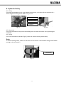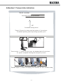
1
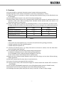
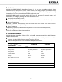
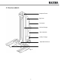
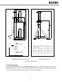
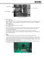
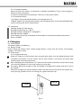
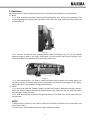
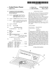
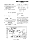
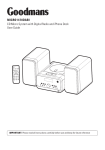
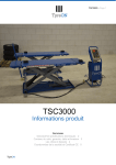
MAXIMA HEAVY DUTY COLUMN LIFT
ML4030B/ML6045B USER MANUAL
CONTENT
1. Cautions ........................................................................................................... - 1 2. Features............................................................................................................ - 3 3. Technical Parameter ......................................................................................... - 3 4. Structure sketch................................................................................................ - 4 5. The Electronics ................................................................................................. - 5 6. Debugging ........................................................................................................ - 8 7. Operation ....................................................................................................... - 10 8. Hydraulic Trolley ............................................................................................. - 11 Addendum 1: Hydraulic valve ............................................................................. - 12 Addendum 2: Transportation Indications ........................................................... - 13 -
1. Cautions
1.1 Do not modify, or maintain electronic control system without permission;
1.2 Working load on each column should be no more than rated load of 7.5 tons;
1.3 Make sure there is no sundry on column tracking surface before lifting, or the slide blocks may
be damaged;
1.4 Load type of electric motor is S2, with 15 minutes working time;
1.5 Maxima Heavy Duty Column Lift is equipped with double safety system of mechanical lock and
hydraulic check valve. Before working under elevated vehicle, please make sure there is no
abnormality with all connections;
1.6 Please use high quality hydraulic oil according to Chart 1. Fill in at least 12 L oil into oil tank.
Change the hydraulic oil after first 100 working hours, and re-change it every 3000 working hours.
N32#
N46#
-4~104 oF
32~104 oF
kinematic viscosity (40oC)mm2/s
30
40
solidifying point oF (≤)
-31
-13
Hydraulic oil
applicative temperature
recommended brand
MOBIL; ESSO; SHELL; HME
Chart 1
Note:
1. Do not fill too much hydraulic oil, in case the oil overflows during lifting procedure;
2. N32#: hydraulic oil of low solidifying point;
3. N46#: wearable hydraulic oil
1.7 Lubricate all relevant parts, e.g. safety hook and its axle once a month; clear the slide block
track and apply some lubricant;
1.8 The elevated vehicle should exactly follow below requirements:
1) Nobody is allowed to stay in vehicle during lifting up/down;
2) It is forbidden to lift a vehicle without enough air in any tire;
3) The vehicle wheels should be parallel to vehicle body;
1.9 Make sure the minimum space between vehicle roof and ceiling is no less than 150mm during
indoor operation;
1.10 DO NOT operate the lift when there is any fault with it;
1.11 Lower all columns onto ground after operation;
1.12 During repair works, the horizontal strength on vehicle should not exceed 20% of vehicle’s
dead weight;
1.13 Do not press UP/DOWN frequently for short lifting/descending, except in SINGLE mode;
1.14 Operate the lift strictly according to instructions and warning in Fig. 1;
1.15 Recharge the battery after daily work or every 10-20 lifts, or after 15 days storage.
-1-
MAXIMA
Safety Instruction
It is necessary to refer to the complete
operation instructions, especially for
trouble shooting.The operation of the lift
is permitted by authorized persons only.
Safety Instruction
Proper inspection and maintenance
before safe operation.
Moveable and mobile lifts must be
prevented from moving unintentionally
Warning
It is forbidden for people to stand in the
field of motion of the load and the load
carrying device during the movement.
Vehicle type
CIPI,CIPIVIII,IIIIIWI.IIPPill
bus,artlculated lorries
lorries and heavy vehicles
Warning
Caution
Never overload lift
The field of motion of the load and of the
load carrying devices shall be free of
obstructions
Warning
Caution
It is forbidden to climb onto the load or
load carrying device when they are
raised unless via a specifically designed
access.
It shall draw attention to the safe method of
carrying theloadand totherulethat,after raising
a short distance, the vehicle shall be checked to
ensurethat it is correctly and safely positioned.
Warning
Caution
Position automobile with center of gravity
at midway between adapters.
It shall draw attention to the rule that the
load carrying dev1ce shall be observed
by the operator throughout the motion of
the lift.
Empty WBiUht [I]
Max.allowed wind speed [ID/S]
from 1 to 10
from 10 to 15
14
20
uraatar than 15
24
Fig. 1
-2-
2. Features
MAXIMA ML4030B/ML6045B Heavy Duty Column Lift is the most up-to-date hydraulic heavy
vehicle lift. Driven by hydraulic cylinder in each column, the lifting arm goes up and down easily
and smoothly. High accuracy balancing system ensures the cylinders working synchronously.
Unique design fits heavy duty vehicle assembling and repair shop.
ML4030B/ML604B applies to vehicles within 30/45 tons for purposes of assembly, repair, and
maintenance, oil-changing, washing and other possible services.
Unique Synchronization System:
To ensure a smooth lift up/down cycle, even when the load on lift is unequally distributed;
Human Engineering:
Operation is available at all columns. One set includes one main column and 3 slave columns
(ML4030B)/ 5slave columns (ML6045B);
Safety measures
Double safety system, mechanical lock and hydraulic check valve ensures safe operation;
Diagnosing Trouble Functions:
It will stop immediately if there is any problem.
3. Technical Parameter
MAXIMA Wireless Heavy Duty Column Lift is designed & manufactured strictly under European
Standard EN1493:1998.
Ground requirements: compression strength ≥ 15MPa; Gradient ≤ 1:200; within the area of the
columns, the level difference must not be more than 10 mm;
Keep the equipment away from combustible or explosive materials.
Model
ML4030B
Specification
ML6045B
Column Numbers
4
6
Lifting Capacity
16,500 lbs per column
16,500 lbs per column
Lifting Stroke
67"
67"
Time of Full Rise
≤120s
≤120s
Voltage
DC 24V
DC 24V
Motor Power per Column
2.2Kw
2.2Kw
Weight per Column
1200 lb
1200 lb
Tire Diameter
19 ~ 44"
19 ~ 44"
Rated Hydraulic Pressure
20Mpa
20Mpa
Axle Stand
optional
optional
Chart 2
-3-
4. Structure sketch
Dustproof cover
Big Cover
Connector
Column Charger
door Hydraulic
trolley Carriage
Adjustable fork arm
Fig. 2
-4-
Range
h1(mm)
h2(mm)
A
1345
1895
B
850
1350
C
400
550
Model
ML4030B Heavy Duty Column Lift
Axle Stand (Optional)
Fig. 3 Equipment sketch
5. The Electronics
The electric control system of ML4030B/ML6045B includes: one master and three slave control
boxes (ML4030B), or five slave control boxes (ML6045B). Each column has one displacement sensor,
one electric hydraulic pump, one microswitch, and one electromagnet.
-5-
“FAULT” light
POWER light
LCD
Emergency button
Connector
Connector
Mode selection knob
“UP” button
Power Switch
“DOWN” button
Fig. 4 Master Control Box
POWER light
“FAULT” light
Emergency button
LCD
Connector
Connector
“UP” button
Power Switch
“DOWN” button
Fig. 5 Slave Control Box
-6-
Safety Hook
Micro-Switch
Electromagnet
Fig. 6 Slave Control Box
5.1. Control switches
5.1.1. Power switch
When this switch is at “OFF”, the lift is powered off and no operation is available; when this
switch is at “ON”, the lift is powered on and prepared for operation. Switch to “CHARGE” to
charge the battery.
5.1.2. “POWER” Light
When the power switch is at “ON”, it is shining.
5.1.3. “FAULT” light
When the carriages overrun the limit synchronous value of the each column or the heavy duty
connector of the cables become loose, it shines. And all the other switches do not work.
5.1.4. Mode selection knob
Turn the knob to “SINGLE”, columns can be operated to go up and down individually;
Turn the knob to “PAIR” or “ALL”, two columns/four columns/six columns can be operated to
go up and down together;
Note:
1. Before turning Mode Selection knob, please power off the lift and wait for 20s first;
2. “PAIR” mode can be used when four/six columns are communicating well. A and B columns
become a pair, same with C and D columns. Please be careful to operate this function. “ALL”
mode is used when there are four/six columns connecting together; “SINGLE” mode can be
used to operate one column individually;
3. In case of an emergency, turn downward the change-over switch (Fig. 7) in control box, so
that the equipment can be operated without communication line;
Fig. 7
-7-
5.1.5. Emergency button
When you press this switch, no operation is available immediately. There is one emergency
button on each control box.
It must be released before lift operation. Then turn on the power switch.
5.1.6. Operation button
“UP” button: Press and hold this button, the carriages will rise.
“DOWN” button: Press and hold this button, the carriages go down to the required height after
system unlocking the hooks automatically.
5.2. Instruction
Working voltage: DC 24V Battery;
Working temperature: 42 ~ 104 oF;
Working humidity: 50%@104 oF -90%@68 oF;
Working altitude: ≤1000m;
Circuit inside control box is forbidden to disassemble or maintenance without permission;
Noise: ≤75dB(A);
6. Debugging
6.1. Power supply
The power supply is 24V Battery;
6.2. Battery charge
Please charge the column when “Please charge battery” occurs onto the screen. The charging
voltage is: AC 220V, 1 phase
6.3. Test process
6.3.1. Single column test
Power on: Connect all 4/6 columns with communication cable, turn the Mode Selection knob
to SINGLE, and power on main column and all slave columns. LCD screen will show work
interface after successful connection.
Rise: Unloaded, press and hold the “UP” button on the master control box, check if the carriage
rises normally. Repeat to try the other columns in same way.
Air release: When the carriage is crawl and wobble in lifting process, please vent the air out of
the cylinder.
Raise the carriages up to about 600mm; loosen the Drain-tap on the top of the cylinder two
turns (see Fig. 8). When there is oil coming out, tighten the Drain-tap.
Drain tap
Cylinder
Fig. 8
-8-
Press endure: Press and hold the “UP” button, the carriage rises to its highest position. After
holding 5 seconds, check and make sure there’s no hydraulic oil leaking out.
Lower: Press and hold the “DOWN” button, the carriages go down to the required height after
the safety hooks unlocked automatically.
Urgency pause: When emergency occurs, just press the red emergency button to stop the lift
& release it after everything is in good condition.
6.3.2. “PAIR” or “ALL” columns test
Power on: Connect all 4/6 columns with communication cable according to Fig. 9, 10, turn the
Mode Selection knob to PAIR or ALL mode, and power on main column and all slave columns.
LCD screen will show work interface after successful connection.
Rise: Unloaded, press and hold the “UP” button at the master control box, check if all the
corresponding carriages can rise normally;
Lower: Press and hold the “DOWN” button, the carriages go down to the required height after
the safety hooks unlocked automatically;
Urgency Pause: When emergency occurs, just press the red emergency button on any column
to stop the system (if equipment continues going, please check electronic control system).
Check and repair the system according to the USER’S TROUBLESHOOTING MANUAL. Then
release it after everything is in good condition.
NOTE:
Please make sure that you have connected all communication cables according to Fig. 9 and 10
before operation.
Fig. 9
Fig. 10
-9-
7. Operation
We introduce four columns operate process here; operation of two columns is the same way.
7.1. Raise
7.1.1. After testing successfully, move the four holding fork arms to their very positions. The
contacting range must equal with the width of the tires. The right position of each column is
shown as Fig.11.
Fig. 11
7.1.2. Connect all columns with communication cable according to Fig. 12, turn the Mode
Selection knob to PAIR or ALL mode, and power on main column and all slave columns. LCD
screen will show work interface after successful connection.
Fig. 12
7.1.3. Press and hold the “UP” button, when the height reaches 10cm, the column stops, and
the beep rings for 2 seconds; please loose the button, and ensure all carriages are lies tightly
against the tires. Then continue lifting up the columns.
7.2. Lower
7.2.1. Press and hold the “DOWN” button to lower the vehicle. When the carriage reaches
30cm, the column stops automatically, and the beep rings, please do not put your feet under
the carriage to avoid any hurts.
7.2.2. After lowering the vehicle to the ground, move the lift away from it and then drive the
vehicle away.
NOTE:
1. When there is vehicle on the system, make sure 4 wheels of vehicle are on same level, and
choose ALL mode;
2. Don't lift any vehicle before hydraulic trolley unloads the press!
- 10 -
8. Hydraulic Trolley
8.1. Lifting
Put down the handlebar, press it up & down several times, in order to lift the column at 30 ~
40mm height from the ground. Refer to Fig. 13, 14.
Lifting bracket
hydraulic trolley
handlebar
Fig. 13
Fig. 14
8.2. Movement
Put up the release bar flatly, move the holding fork arm under the vehicle tire by pushing the
handlebar.
8.3. Falling
Put up the release bar upwards (Fig.15), lower the column to the ground slowly.
Note:
To avoid crushing hands, make sure the doors of the electric control boxes being closed before
putting up the release bar!
Release bar
Fig. 15
- 11 -
Addendum 1: Hydraulic valve
- 12 -
Addendum 2: Transportation Indications
Serial number :
Plac ed and Sc oop up direc tion:
UP
Forbidden falling dow n!
Trans it :Ex c ept the beam and the bottom of the c olum n ,
Forbidden pac k ing and s us pending any other part !
横梁
beam
Trans it s ty le 1 : beam c an only bear the deadw eight of the c olum n ,
s o perm it s us pend it during the trans port proc es s .
Fork lift
>2 0 0 mm
The bottom of the column
Forklift arm
Tra n sit style 2 :Allo w sco o p in g th e b o tto m o f th e co lu mn e lse!
- 13 -