1
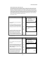
INSTRUCTION MANUAL
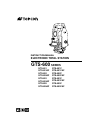
ELECTRONIC TOTAL STATION
GTS-600 SERIES
GTS-601
GTS-601AF
GTS-602
GTS-602AF
GTS-603
GTS-603AF
GTS-605
GTS-605AF
GTS-601C
GTS-601CAF
GTS-602C
GTS-602CAF
GTS-603C
GTS-603CAF
GTS-605C
GTS-605CAF
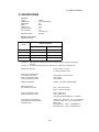
FOREWORD
FOREWORD
Thank you for purchasing the TOPCON Electronic Total Station, GTS-600 series.
For the best performance of the instruments, please carefully read these instructions
and keep them in a convenient location for future reference.
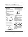
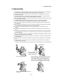
General Handling Precautions
Before starting work or operation, be sure to check that the instrument is
functioning correctly with normal performance.
Do not aim the instrument directly into the sun .
Aiming the instrument directly into the sun can result in serious damage to the eyes.
Damage to the instrument could also result from exposing the instrument’s objective lens to
direct sunlight. The use of a solar filter is suggested to alleviate this problem.
Setting the instrument on a tripod
When mounting the instrument on a tripod, use a wooden tripod when possible. The
vibrations that may occur when using a metallic tripod can effect the measuring precision.
Installing the tribrach
If the tribrach is installed incorrectly , the measuring precision could be effected.
Occasionally check the adjusting screws on the tribrach. Make sure the base fixing lever is
locked and the base fixing screws are tightened.
Guarding the instrument against shocks
When transporting the instrument, provide some protection to minimize risk of shocks.
Heavy shocks may cause the measurement to be faulty.
Carrying the instrument
Always carry the instrument by its handgrip.
Exposing the instrument to extreme heat.
Do not leave the instrument in extreme heat for longer than necessary. It could adversely
affect its performance.
Sudden changes of temperature
Any sudden change of temperature to the instrument or prism may result in a reduction of
measuring distance range, i.e when taking the instrument out from a heated vehicle. Let
instrument acclimate itself to ambient temperature.
Battery level check
Confirm battery level remaining before operating.
Memory back up
The instrument has a built in battery for memory back up. If the battery power is low, “Back
up battery empty” will display. Contact your dealer, to replace the battery.
Taking the battery out
It is recommended not to take the battery out during the power is on. All the data stored is
possible gone at that time. So please do your assembling or taking the battery out after the
power is off.
No responsibility
TOPCON Corporation has no responsibility for loss of data stored in the memory in case
unexpected accidents.
1
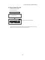
FOREWORD
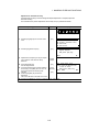
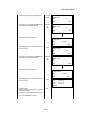
Display for Safe Use
In order to encourage the safe use of products and prevent any danger to the operator and
others or damage to properties, important warnings are put on the products and inserted in the
instruction manuals.
We suggest that everyone understand the meaning of the following displays and icons before
reading the “Safety Cautions” and text.
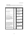
Meaning
Display
WARNING
Ignoring or disregard of this display may lead to the danger of death or
serious injury.
CAUTION
Ignoring or disregard of this display may lead to personal injury or physical damage.
WARNING
CAUTION
•Injury refers to hurt, burn, electric shock, etc.
•Physical damage refers to extensive damage to buildings or equipment and furniture.
Safety Cautions
WARNING
WARNING
•There is a risk of fire, electric shock or physical harm if you attempt to disassemble or
repair the instrument yourself.
This is only to be carried out by TOPCON or an authorized dealer, only!
•Cause eye injury or blindness.
Do not look at the sun through a telescope.
•Laser beams can be dangerous, and can cause eye injury's if used incorrectly.
Never attempt to repair the instrument yourself. (Only for Laser plummet type)
•Cause eye injury or blindness.
Do not stare into beam. (Only for Laser plummet type)
•High temperature may cause fire.
Do not cover the charger while it is charging.
•Risk of fire or electric shock.
Do not use damaged power cable, plug and socket.
•Risk of fire or electric shock.
Do not use a wet battery or charger.
•May ignite explosively.
Never use an instrument near flammable gas, liquid matter, and do not use in a coal mine.
•Battery can cause explosion or injury.
Do not dispose in fire or heat.
•Risk of fire or electric shock.
Do not use any power voltage except the one given on manufacturers instructions.
•Battery can cause outbreak of fire.
Do not use any other type of charger other than the one specified.
•Risk of fire.
Do not use any other power cable other than the one specified.
•The short circuit of a battery can cause a fire.
Do not short circuit battery when storing it.
2
FOREWORD
CAUTION
CAUTION
•Use of controls or adjustment or performance of procedures other than those specified herein
may result in hazardous radiation exposure. (Only for Laser plummet type)
•Do not connect or disconnect equipment with wet hands, you are at risk of electric shocks if you
do!
•Risk of injury by overturn the carrying case.
Do not stand or sit on the carrying cases.
•Please note that the tips of tripod can be hazardous, be aware of this when setting up or carrying the tripod.
•Risk of injury by falling down the instrument or case.
Do not use a carrying case with a damaged which belts, grips or latches .
•Do not allow skin or clothing to come into contact with acid from the batteries, if this does occur
then wash off with copious amounts of water and seek medical advice.
•A plumb bob can cause an injury to a person if used incorrectly.
•It could be dangerous if the instrument falls over, please ensure you attach a handle batter
the instrument securely.
•Ensure that you mount the Tribrach correctly, failing to do so may result in injury if the tribrach
were to fall over.
•It could be dangerous if the instrument falls over, please check that you fix the instrument to
the tripod correctly.
•Risk of injury by falling down a tripod and an instrument.
y to
Always check that the screws of tripod are tightened.
User
1)
2)
This product is for professional use only!
The user is required to be a qualified surveyor or have a good knowledge of surveying, in order
to understand the user and safety instructions, before operating, inspecting or adjusting.
Wear the required protectors (safety shoes, helmet, etc.) when operating.
Exceptions from Responsibility
1)
2)
3)
4)
5)
6)
The user of this product is expected to follow all operating instructions and make periodic checks
of the product’s performance.
The manufacturer, or its representatives, assumes no responsibility for results of a faulty or
intentional usage or misuse including any direct, indirect, consequential damage, and loss of
profits.
The manufacturer, or its representatives, assumes no responsibility for consequential damage,
and loss of profits by any disaster, (an earthquake, storms, floods etc.).
A fire, accident, or an act of a third party and/or a usage any other usual conditions.
The manufacturer, or its representatives, assumes no responsibility for any damage, and loss of
profits due to a change of data, loss of data, an interruption of business etc., caused by using the
product or an unusable product.
The manufacturer, or its representatives, assumes no responsibility for any damage, and loss of
profits caused by usage except for explained in the user manual.
The manufacturer, or its representatives, assumes no responsibility for damage caused by wrong
movement, or action due to connecting with other products.
3
FOREWORD
Safety Standard for Laser Beam
GTS-600 series Laser plummet type use a visible laser beam to perform the plumb laser function.
The GTS-600 series Laser plummet type products are manufactured and sold in accordance with
"Radiation Safety of Laser Products, Equipment Classification, Requirements and User`s Guide"
(IEC Publication 825) or "Performance Standards for Light-Emitting Products" (FDA/BRH 21 CFR
1040) regarding the safety standard for laser products.
As per these standards, the GTS-600 series Laser plummet type is classified as "Class II (2) Laser
Products".
Since Laser radiation is emitted from the GTS-600 series Laser plummet type instruments, please
refer to the "Laser Safety" bulletin which accompanies the instrument in the United States as well as
the "Safety Standard for Users" that is mentioned in the instruction manual. In the case of any technical failure, do not disassemble the instrument. Contact either TOPCON or your authorized
TOPCON dealer.
Caution:
Use of controls or adjustments or performance of procedure than those specified in this manual
may result in hazardous radiation exposure.
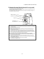
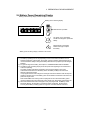
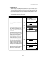
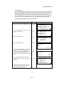
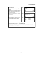
Labels
The following labels are found on the instruments which describe the GTS-600 series Laser
plummet type: Precautions and safety information about the laser beam.
If, at any time, any of these labels are damaged and become illegible, please replace these
mportant labels. Please the new labels in exactly the same position as the original labels.
Replacement labels can be obtained from Topcon or your authorized Topcon dealer.
GTS-600 series Laser Plummet type
y
Warning Label
Explanatory Label
CAUTION
LASER RADIATION-DO NOT
STARE INTO BEAM
WAVE LENGTH 633nm
1mW MAXIMUM OUTPUT
CLASS IILASER PRODUCT
Aperture Label
LASER RADIATION
AVOID EXPOSURE
DO NOT STARE INTO BEAM
LASER LIGHT IS EMITTED
FROM THIS APERTURE
Maximum output 1ÇçWÅ@ Wave length 633nm
CLASS 2Å@LASER PRODUCT
Beam aperture
Depending on the country where the instrument is sold, either of these labels may be
found on the GTS-600 series laser plummet type.
4
FOREWORD
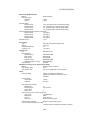
Contents
FOREWORD . . . . . . . . . . . . . . . . . . . . . . . . . . . . . . . . . . . . . . . . . . . . . .
General Handling Precautions . . . . . . . . . . . . . . . . . . . . . . . . . . . . . . . . . . . . . . . . . .
Display for Safe Use . . . . . . . . . . . . . . . . . . . . . . . . . . . . . . . . . . . . . . . . . . . . . . . . .
Safety Cautions . . . . . . . . . . . . . . . . . . . . . . . . . . . . . . . . . . . . . . . . . . . . . . . . . . . . .
User . . . . . . . . . . . . . . . . . . . . . . . . . . . . . . . . . . . . . . . . . . . . . . . . . . . . . . . . . . . . .
Exceptions from Responsibility . . . . . . . . . . . . . . . . . . . . . . . . . . . . . . . . . . . . . . . . .
Safety Standard for Laser Beam . . . . . . . . . . . . . . . . . . . . . . . . . . . . . . . . . . . . . . . .
Contents . . . . . . . . . . . . . . . . . . . . . . . . . . . . . . . . . . . . . . . . . . . . . . . . . . . . . . . . . .
Standard Set Composition . . . . . . . . . . . . . . . . . . . . . . . . . . . . . . . . . . . . . . . . . . . . .
1
1
2
2
3
3
4
5
7
1 NOMENCLATURE AND FUNCTIONS . . . . . . . . . . . . . . . . . . . . . . . . . .
1-1
1.1 Nomenclature . . . . . . . . . . . . . . . . . . . . . . . . . . . . . . . . . . . . . . . . . . . . . . . . . . .
1.2 Display . . . . . . . . . . . . . . . . . . . . . . . . . . . . . . . . . . . . . . . . . . . . . . . . . . . . . . . .
1.3 Operating Key. . . . . . . . . . . . . . . . . . . . . . . . . . . . . . . . . . . . . . . . . . . . . . . . . . . .
1.4 Function Key (Soft Key) . . . . . . . . . . . . . . . . . . . . . . . . . . . . . . . . . . . . . . . . . . . .
1.5 Star key mode . . . . . . . . . . . . . . . . . . . . . . . . . . . . . . . . . . . . . . . . . . . . . . . . . . .
1.6 Auto Power Off . . . . . . . . . . . . . . . . . . . . . . . . . . . . . . . . . . . . . . . . . . . . . . . . . .
1.7 Automatic Focusing (Only for Automatic Focusing model) . . . . . . . . . . . . . . . . . . .
1-1
1-4
1-5
1-5
1-7
1-10
1-11
2 PREPARATION FOR MEASUREMENT . . . . . . . . . . . . . . . . . . . . . . . . .
2-1
2.1 Power Connection . . . . . . . . . . . . . . . . . . . . . . . . . . . . . . . . . . . . . . . . . . . . . . . .
2.2 Setting Instrument Up For Measurement . . . . . . . . . . . . . . . . . . . . . . . . . . . . . . .
2.3 Power Switch Key ON . . . . . . . . . . . . . . . . . . . . . . . . . . . . . . . . . . . . . . . . . . . . .
2.4 Battery Power Remaining Display . . . . . . . . . . . . . . . . . . . . . . . . . . . . . . . . . . . .
2.5 Main Menu Contains. . . . . . . . . . . . . . . . . . . . . . . . . . . . . . . . . . . . . . . . . . . . . . .
2.6 Vertical and Horizontal Angle Tilt Correction . . . . . . . . . . . . . . . . . . . . . . . . . . . .
2.7 Compensation of Systematic Error of Instrument . . . . . . . . . . . . . . . . . . . . . . . . .
2.8 Resume Mode ON/OFF . . . . . . . . . . . . . . . . . . . . . . . . . . . . . . . . . . . . . . . . . . . .
2.9 How to Enter Numerals and Alphabet Letters . . . . . . . . . . . . . . . . . . . . . . . . . . . .
2.10 Data Memory Card (Only for Card model) . . . . . . . . . . . . . . . . . . . . . . . . . . . . .
2-1
2-2
2-3
2-4
2-5
2-6
2-7
2-8
2-8
2-9
3 STANDARD MEASUREMENT MODE . . . . . . . . . . . . . . . . . . . . . . . . . .
3-1
3.1 Angle Measurement . . . . . . . . . . . . . . . . . . . . . . . . . . . . . . . . . . . . . . . . . . . . . . .
3.1.1 Measuring Horizontal Angle Right and Vertical Angle . . . . . . . . . . . . . . . . .
3.1.2 Switching Horizontal Angle Right/Left . . . . . . . . . . . . . . . . . . . . . . . . . . . . .
3.1.3 Measuring from the Required Horizontal Angle . . . . . . . . . . . . . . . . . . . . .
3.1.4 Vertical Angle Percent Grade(%) Mode. . . . . . . . . . . . . . . . . . . . . . . . . . . .
3.2 Distance Measurement. . . . . . . . . . . . . . . . . . . . . . . . . . . . . . . . . . . . . . . . . . . . .
3.2.1 Setting of the Atmospheric Correction . . . . . . . . . . . . . . . . . . . . . . . . . . . .
3.2.2 Setting of the Correction for Prism Constant . . . . . . . . . . . . . . . . . . . . . . .
3.2.3 Distance Measurement (Continuous Measurement) . . . . . . . . . . . . . . . . . .
3.2.4 Distance Measurement (Single/N-times Measurement) . . . . . . . . . . . . . . .
3.2.5 Fine/ Tracking / Coarse Measuring Mode . . . . . . . . . . . . . . . . . . . . . . . . . .
3.2.6 Stake Out (S-O) . . . . . . . . . . . . . . . . . . . . . . . . . . . . . . . . . . . . . . . . . . . .
3.3 COORDINATE MEASUREMENT . . . . . . . . . . . . . . . . . . . . . . . . . . . . . . . . . . . . .
3.3.1 Setting Coordinate Values of Occupied Point . . . . . . . . . . . . . . . . . . . . . . .
3.3.2 Setting of the Instrument Height / Prism Height . . . . . . . . . . . . . . . . . . . . .
3.3.3 Execution of Coordinate Measuring . . . . . . . . . . . . . . . . . . . . . . . . . . . . . .
3.4 DATA OUTPUT . . . . . . . . . . . . . . . . . . . . . . . . . . . . . . . . . . . . . . . . . . . . . . . . . .
3.5 DATA Output by soft key (REC) . . . . . . . . . . . . . . . . . . . . . . . . . . . . . . . . . . . . . .
3-1
3-1
3-2
3-2
3-3
3-4
3-4
3-4
3-4
3-5
3-7
3-8
3-9
3-9
3-11
3-12
3-14
3-15
4 PROGRAM MODE . . . . . . . . . . . . . . . . . . . . . . . . . . . . . . . . . . . . . . . . . 4-1
4.1 Setting a Direction Angle for Backsight Orientation . . . . . . . . . . . . . . . . . . . . . . . .
4.2 Retaining a Coordinate (STORE- NEZ) . . . . . . . . . . . . . . . . . . . . . . . . . . . . . . . .
4.3 Remote Elevation measurement (REM) . . . . . . . . . . . . . . . . . . . . . . . . . . . . . . . .
4.4 Missing Line Measurement (MLM) . . . . . . . . . . . . . . . . . . . . . . . . . . . . . . . . . . . .
4.5 Repetition Angle Measurement (REP) .. . . . . . . . . . . . . . . . . . . . . . . . . . . . . . . . .
4.6 Layout . . . . . . . . . . . . . . . . . . . . . . . . . . . . . . . . . . . . . . . . . . . . . . . . . . . . . . . . .
4.6.1 Options . . . . . . . . . . . . . . . . . . . . . . . . . . . . . . . . . . . . . . . . . . . . . . . . . . . . . . .
4.6.2 Coordinate Data . . . . . . . . . . . . . . . . . . . . . . . . . . . . . . . . . . . . . . . . . . . . .
4.6.3 Search Data and View Jobs . . . . . . . . . . . . . . . . . . . . . . . . . . . . . . . . . . .
4.6.4 New Point . . . . . . . . . . . . . . . . . . . . . . . . . . . . . . . . . . . . . . . . . . . . . . . . .
4.6.5 Grid Factor . . . . . . . . . . . . . . . . . . . . . . . . . . . . . . . . . . . . . . . . . . . . . . . .
4.6.6 Setting a Direction Angle and Layout a Point . . . . . . . . . . . . . . . . . . . . . . .
5
4-2
4-3
4-5
4-8
4-10
4-12
4-13
4-22
4-24
4-26
4-31
4-33
FOREWORD
4.6.7 Guidance Feature . . . . . . . . . . . . . . . . . . . . . . . . . . . . . . . . . . . . . . . . . .
4.7 Line Measurement (LINE) . . . . . . . . . . . . . . . . . . . . . . . . . . . . . . . . . . . . . . . . . .
4.8 Offset measurement (OFFSET) . . . . . . . . . . . . . . . . . . . . . . . . . . . . . . . . . . . . .
4.8.1 Angle Offset . . . . . . . . . . . . . . . . . . . . . . . . . . . . . . . . . . . . . . . . . . . . . .
4.8.2 Distance Offset Measurement . . . . . . . . . . . . . . . . . . . . . . . . . . . . . . . . . .
4.8.3 Plane Offset Measurement . . . . . . . . . . . . . . . . . . . . . . . . . . . . . . . . . . . .
4.8.4 Column Offset Measurement . . . . . . . . . . . . . . . . . . . . . . . . . . . . . . . . . .
4.9 LOADER option . . . . . . . . . . . . . . . . . . . . . . . . . . . . . . . . . . . . . . . . . . . . . . . . .
5 MEMORY MANAGE MODE . . . . . . . . . . . . . . . . . . . . . . . . . . . . . . . . . .
5.1
5.2
5.3
5.4
5.5
5.6
5.7
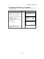
View Internal Memory Status (for normal model) . . . . . . . . . . . . . . . . . . . . . . . . .
View Internal Memory and Card Memory Status (for Card model) . . . . . . . . . . . .
Protecting a File . . . . . . . . . . . . . . . . . . . . . . . . . . . . . . . . . . . . . . . . . . . . . . . . .
Rename a File . . . . . . . . . . . . . . . . . . . . . . . . . . . . . . . . . . . . . . . . . . . . . . . . . . .
Deleting a File . . . . . . . . . . . . . . . . . . . . . . . . . . . . . . . . . . . . . . . . . . . . . . . . . . .
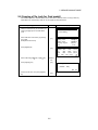
Copying a File (only for Card model) . . . . . . . . . . . . . . . . . . . . . . . . . . . . . . . . . .
Initializing Internal Memory or Card Memory . . . . . . . . . . . . . . . . . . . . . . . . . . . . .
4-37
4-38
4-41
4-42
4-44
4-46
4-48
4-50
5-1
5-1
5-1
5-2
5-3
5-4
5-5
5-6
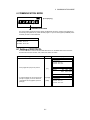
6 COMMUNICATION MODE . . . . . . . . . . . . . . . . . . . . . . . . . . . . . . . . . . . 6-1
6.1 Setting of PROTOCOL . . . . . . . . . . . . . . . . . . . . . . . . . . . . . . . . . . . . . . . . . . . .
6.2 Data file in . . . . . . . . . . . . . . . . . . . . . . . . . . . . . . . . . . . . . . . . . . . . . . . . . . . . . .
6.3 Data file out . . . . . . . . . . . . . . . . . . . . . . . . . . . . . . . . . . . . . . . . . . . . . . . . . . . . .
6-1
6-2
6-3
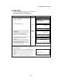
7 PARAMETERS SETTING MODE . . . . . . . . . . . . . . . . . . . . . . . . . . . . . . 7-1
7.1 Parameter Setting Options . . . . . . . . . . . . . . . . . . . . . . . . . . . . . . . . . . . . . . . . . .
7.1.1 Parameters for Measurement and Display . . . . . . . . . . . . . . . . . . . . . . . . .
7.1.2 Parameters for communication . . . . . . . . . . . . . . . . . . . . . . . . . . . . . . . .
7.2 Setting Parameters . . . . . . . . . . . . . . . . . . . . . . . . . . . . . . . . . . . . . . . . . . . . . .
7.2.1 Parameters for Measurement and Display . . . . . . . . . . . . . . . . . . . . . . . . .
7.2.2 Parameters for communication . . . . . . . . . . . . . . . . . . . . . . . . . . . . . . . .
7.2.3 Password option . . . . . . . . . . . . . . . . . . . . . . . . . . . . . . . . . . . . . . . . . . . .
7-1
7-1
7-3
7-4
7-4
7-5
7-6
8 CHECK AND ADJUSTMENT . . . . . . . . . . . . . . . . . . . . . . . . . . . . . . . . . 8-1
8.1 Checking and adjusting of instrument constant . . . . . . . . . . . . . . . . . . . . . . . . . . .
8.2 Checking the Optical Axis . . . . . . . . . . . . . . . . . . . . . . . . . . . . . . . . . . . . . . . . . .
8.3 Checking/Adjusting the Theodolite Functions . . . . . . . . . . . . . . . . . . . . . . . . . . .
8.3.1 Checking /Adjusting the Plate Level . . . . . . . . . . . . . . . . . . . . . . . . . . . . . .
8.3.2 Checking /Adjusting the Circular Level . . . . . . . . . . . . . . . . . . . . . . . . . . .
8.3.3 Adjustment of the Vertical Cross-hair . . . . . . . . . . . . . . . . . . . . . . . . . . . . .
8.3.4 Collimation of the Instrument . . . . . . . . . . . . . . . . . . . . . . . . . . . . . . . . . .
8.3.5 Checking / Adjusting the Optical Plummet Telescope . . . . . . . . . . . . . . . . .
8.3.6 Checking / Adjusting the Laser Plummet (For Laser Plummet type) . . . . . .
8.4 Adjustment of Compensation Systematic Error of Instrument . . . . . . . . . . . . . . .
8.5 Showing Constant List and Switch ON/OFF
Compensation Systematic Error of Instrument . . . . . . . . . . . . . . . . . . . . . . . . . . . . . .
8.6 How to adjust the date and time
....................................
8.7 How to Set the Instrument Constant Value . . . . . . . . . . . . . . . . . . . . . . . . . . . . . .
8.8 Reference Frequency Checking Mode . . . . . . . . . . . . . . . . . . . . . . . . . . . . . . . .
8-1
8-2
8-3
8-4
8-4
8-5
8-6
8-7
8-8
8-9
8-11
8-12
8-13
8-14
9 SETTING THE PRISM CONSTANT VALUE . . . . . . . . . . . . . . . . . . . . . . 9-1
10 SETTING ATMOSPHERIC CORRECTION . . . . . . . . . . . . . . . . . . . . . . 10-1
10.1 Calculation of Atmospheric Correction . . . . . . . . . . . . . . . . . . . . . . . . . . . . . . . .
10.2 Setting of Atmospheric Correction Value . . . . . . . . . . . . . . . . . . . . . . . . . . . . . .
10-1
10-1
11 CORRECTIONFORREFRACTIONANDEARTHCURVATURE . . . . . . . . . . . . . . . . 11-1
11.1 Distance Calculation Formula . . . . . . . . . . . . . . . . . . . . . . . . . . . . . . . . . . . . . . .
11-1
12 POWER SOURCE AND CHARGING . . . . . . . . . . . . . . . . . . . . . . . . . . 12-1
12.1 On-board Battery BT-50Q . . . . . . . . . . . . . . . . . . . . . . . . . . . . . . . . . . . .. . . . . . . 12-1
13
14
15
16
17
DETACH/ATTACH OF TRIBRACH . . . . . . . . . . . . . . . . . . . . . . . . . . . .
SPECIAL ACCESSORIES . . . . . . . . . . . . . . . . . . . . . . . . . . . . . . . . . .
BATTERY SYSTEM . . . . . . . . . . . . . . . . . . . . . . . . . . . . . . . . . . . . . . .
PRISM SYSTEM . . . . . . . . . . . . . . . . . . . . . . . . . . . . . . . . . . . . . . . . . .
PRECAUTIONS . . . . . . . . . . . . . . . . . . . . . . . . . . . . . . . . . . . . . . . . . .
6
13-1
14-1
15-1
16-1
17-1
FOREWORD
18 ERROR DISPLAYS . . . . . . . . . . . . . . . . . . . . . . . . . . . . . . . . . . . . . . . 18-1
19 SPECIFICATIONS . . . . . . . . . . . . . . . . . . . . . . . . . . . . . . . . . . . . . . . . 19-1
APPENDIX . . . . . . . . . . . . . . . . . . . . . . . . . . . . . . . . . . . . . . . . . APPENDIX-1
Dual Axis Compensation ....................................................................................... APPENDIX-1
Precaution when Charging or Storing Batteries..................................................... APPENDIX-3
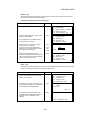
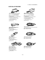
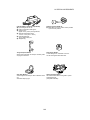
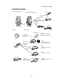
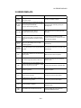
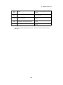
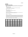
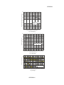
Standard Set Composition
1) GTS-600 series (with lens cap) . . . . . . . . . . . . . . . . . . . . . . . . . . . . . . . . . . . . . . . . . .
2) Battery BT-50Q . . . . . . . . . . . . . . . . . . . . . . . . . . . . . . . . . . . . . . . . . . . . . . . . . . . . . .
3) Battery charger BC-27BR or BC-27CR . . . . . . . . . . . . .. . . . . . . . . . . . . . . . . . . . . . . .
4) Tool kit with case [ rod pins, screwdriver, cleaning brush ] . . . . . . . . . . . . . . . . . . . . . .
5) Plastic carrying case . . . . . . . . . . . . . . . . . . . . . . . . . . . . . . . . . . . . . . . . . . . . . . . . . .
6) Sun shade . . . . . . . . . . . . . . . . . . . . . . . . . . . . . . . . . . . . . . . . . . . . . . . . . . . . . . . . .
7) Plastic rain cover . . . . . . . . . . . . . . . . . . . . . . . . . . . . . . . . . . . . . . . . . . . . . . . . . . . . .
8) Silicon cloth . . . . . . . . . . . . . . . . . . . . . . . . . . . . . . . . . . . . . . . . . . . . . . . . . . . . . . . . .
9) Instruction manual . . . . . . . . . . . . . . . . . . . . . . . . . . . . . . . . . . . . . . . . . . . . . . . . . . . .
(Make sure that all of the above items are with the instrument when purchased.)
Remarks:
1) Battery charger BC-27CR is for AC 230V use and BC-27BR is for AC 120V use.
2) Plumb bob set and plumb bob hook are supplied for certain markets.
3) Additional on-board battery BT-50Q is included for certain markets
7
1 each
1 each
1 each
1 set
1 each
1 each
1 each
1each
1 each
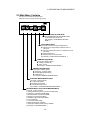
1 NOMENCLATURE AND FUNCTIONS
1 NOMENCLATURE AND FUNCTIONS
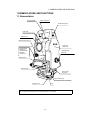
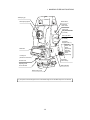
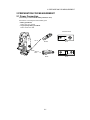
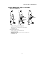
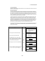
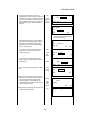
1.1 Nomenclature
Carrying handle
Sighting collimator
Handle fixing screw
Point guide
(P oint guide type only)
Objective lens
Vertical motion clamp *1)
Instrument
center mark
Vertical tangent screw *1)2)
GTS-601series:
2speed way
GTS-603series/
605series:
1speed way
Optical plummet
telescope
Display window
Operation keys
Power supply
connector
Communication port
(Serial signal connector RS-232C)
Leveling screw
Base
*1) The position of vertical motion clamp and tangent screw will differ depend on the markets.
*2) The speed of vertical tangent screw will differ depend on the markets.
1-1
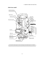
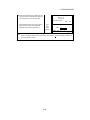
1 NOMENCLATURE AND FUNCTIONS
Telescope grip
Telescope eyepiece
Power switch
Instrument
center mark
Card cover
Only for Card model
(C model)
Card cover lever
Only f or Card model
(C model)
Horizontal
tangent screw *1)
GTS-601
series / 602
series:
2speed way
GTS-603
series /605
series:
1speed way
Plate level
Printer port
(Centronics connector)
Horizontal
motion clamp
Circular level
Adjusting screw
for circular level
Battery BT-50Q
Tr ibrach fixing lever
*1) The speed of vertical tangent screw and horizontal tangent screw will differ depend on the markets.
1-2
1 NOMENCLATURE AND FUNCTIONS
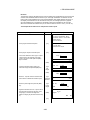
Auto-focus model
Automatic focusing key
Telescope grip
Telescope eyepiece
Power switch
Instrument
center mark
Manual focusing knob
Card cover
Only for Card model
(C model)
Card cover lever
Only for Card model
(C model)
Horizontal
tangent screw *1)
GTS-601
series / 602
series:
2speed way
GTS-603
series /605
series:
1speed way
Plate level
Printer port
(Centronics connector)
Horizontal
motion clamp
Circular level
Adjusting screw
for circular level
Battery BT-50Q
Tr ibrach fixing lever
*1) The speed of vertical tangent screw and horizontal tangent screw will differ depend on the markets.
1-3
1 NOMENCLATURE AND FUNCTIONS
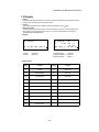
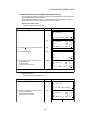
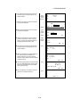
1.2 Display
• Display
In general upper fore lines display the measuring data, and the bottom line displays the soft key
function which is changed by the measuring mode.
• Contrast
The contrast and illumination of display window are adjusted by star (
)key.
• Heater (Automatic)
The built-in automatic heater functions when the temperature is below 0°C.This keeps the display's speed up at temperatures lower than 0°C. To set the heater ON/OFF, see Chapter 7
“PARAMETERS SETTING MODE” .
• Example
V : 87°55'20"
HR: 180°44'12"
SD
HD
NEZ
0SET
HOLD
V : 87°55'40"
HR: 180°44'12"
PSM
0.0
SD:
12.345 PPM
0.0
(m) *F.R
MEAS MODE VH
HD NEZ P1
P1
Angle measurement mode
Distance measurement mode
V-angle
H-angle
Horizontal-angle
: 87°55’40”
Horizontal distance : 180°44’12”
Relative elevation : 12.345m
: 87°55’20”
: 180°44’12”
• Display marks
Display
Contents
Display
Content
V
V -angle
(m)
Meter unit
V%
Percent grade
(f)
Feet unit
HR
H-angle right
F
Fine mode
HL
H-angle left
C
Coarse mode
HD
Horizontal distance
T
Tracking mode
VD
Relative elevation
R
Repeat measurement
SD
Slope distance
S
Single measurement
N
N coordinate
N
N-times measurement
E
E coordinate
ppm
Atmospheric correction value
Z
Z coordinate
psm
Prism constant value
✻
EDM working
1-4
1 NOMENCLATURE AND FUNCTIONS
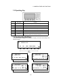
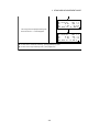
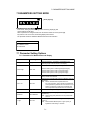
1.3 Operating Key
Keys
Name of Key
Function
F1~F6
Soft key
0~9
Numeric key
Entering numerals.
A ~/
Alpha key
Entering Alphabets.
ESC
Escape key
★
Star key
Star key mode is used for each presetting or displaying.
ENT
Enter key
Press at the end of inputting values.
POWER
Power key
ON/OFF of power source.
(Power key is located on the side of the instrument.)
Functions are according to the displayed message.
Returning to the previous mode or display.
1.4 Function Key (Soft Key)
The Soft Key message is displayed at the bottom line of display. The functions are according to the
displayed message.
V : 87°55'45"5
HR: 180°44'12"5
SD
[F1]
HD
NEZ
[F2]
[F3]
0SET HOLD
P1
[F5]
[F6]
[F4]
Soft keys
V : 90°10'20"5
HR: 120°30'40"5
SD:
V : 87°55'45"5
HR: 180°44'12"5
PSM
PPM
(m)
MEAS MODE VH HD NEZ
REC SO MEAN m/ft
SD HD NEZ 0SET HOLD P1
REC HSET R/L V/% TILT P2
V : 90 10'20"5
HR: 120 30'40"5 PSM
0.0
HD:
PPM
0.0
VD:
(m) F.R
MEAS MODE VH SD NEZ P1
MEAN
m/ft
P2
Slope distance measuring
Angle measuring
REC SO
0.0
0.0
F.R
P1
N : 12345.6789
E : -12345.6789
Z :
10.1234
MEAS MODE VH
P2
SD
PSM 0.0
PPM 0.0
(m) F.R
HD P1
REC HT MEAN m/ft SET P2
Coordinate measuring
Horizontal distance measuring
1-5
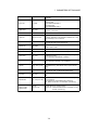
1 NOMENCLATURE AND FUNCTIONS
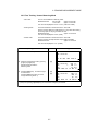
Display
Soft
key
SD
HD
NEZ
0SET
HOLD
REC
HSET
R/L
V/%
F1
F2
F3
F4
F5
F1
F2
F3
F4
TILT
F5
MEAS
F1
MODE
VH
HD
NEZ
REC
SO
MEAN
m/ft
F2
F3
F4
F5
F1
F2
F3
F4
MEAS
F1
MODE
VH
SD
NEZ
REC
SO
MEAN
m/ft
F2
F3
F4
F5
F1
F2
F3
F4
MEAS
F1
Coordinate MODE
measuring
VH
SD
HD
REC
HT
MEAN
m/ft
SET
F2
F3
F4
F5
F1
F2
F3
F4
F5
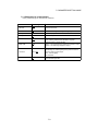
Page
Angle
measuring
Slope
distance
measuring
Horizontal
distance
measuring
Function
To be slope distance measuring mode.
To be horizontal distance measuring mode.
To be coordinate distance measuring mode.
Angle of horizontal is set to 0 00'00".
Hold the horizontal angle.
To be measurement data record mode.
Sets the horizontal angle by input value.
Switches R/L rotation of horizontal angle.
Switches the vertical angle and percent grade
Sets the tilt function, ON/OFF.
If ON, the display shows tilt correction value.
Slope distance measuring starts.
Switches Continuous/ N-times (Single) measurement mode.
Set to the mode for Tracking , Coarse or Fine.
To be angle measurement mode.
To be horizontal distance measurement mode.
To be coordinate measurement mode.
To be measurement data record mode.
To be stake out measurement mode.
Sets the number of N-time measurement.
Switches meter or feet unit.
Horizontal distance measuring starts.
Switches Continuous/ .N-times (Single) measurement mode.
Set to the mode for Tracking , Coarse or Fine.
To be angle measurement mode.
To be slope distance measurement mode.
To be coordinate measurement mode.
To be measurement data record mode.
To be stake out measurement mode.
Sets the number of N-time measurement.
Switches meter or feet unit.
Coordinate measuring starts.
Switches Continuous/ N-times (Single) measurement mode.
Set to the mode for Tracking , Coarse or Fine.
To be angle measurement mode.
To be slope distance measurement mode.
To be horizontal distance measurement mode.
To be measurement data record mode.
Sets an Instrument Height / Prism Height by input values.
Sets the number of N-time measurement.
Switches meter or feet unit.
Sets an instrument coordinate point by input values.
1-6
1 NOMENCLATURE AND FUNCTIONS
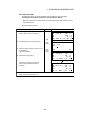
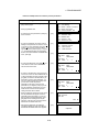
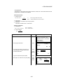
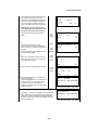
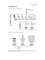
1.5 Star key mode
Press the (
)key to view the instrument options. Since there are two screens of options, press [F6]
(1 ) soft key to view the next screen.
The following instrument options can be selected from the (
):
• Screen One
1. View Date & Time
2. Adjustment the contrast of the display [F1 & F2]
3. Turn the backlight of the display ON/OFF [F3]
4. Reticle illumination--ON(1to9 steps) / OFF [F4]
5. View free memory for internal memory [F5]
(Card model can be displayed free memory for card memory.)
• Screen Two
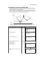
6. Electric circular graphic display[F1]
7. The light acceptance quantity level (signal level) is displayed.[F2]
8. Set the Temperature, Pressure, Atmospheric Correction Value (PPM), and Prism Constant Value
(PSM) [F3]
9. Turn the Point Guide option ON/OFF [F4](Only for point guide type)
10. Turn the Laser Plummet ON/OFF [F5] (Only for laser plummet type)
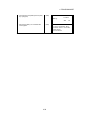
Contrast Adjustment
Date & Time
Reticle Illumination
2001-07-10 14:30:40
Screen 1
5
1
o
Backlight of display
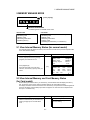
Displaying the Internal Memory Capacity
Card model can display free memory for the Internal Memory and Card
memory. The icon will change as follows.
Electric Circular Graphic Display
Displaying Signal Level
Date & Time
2001-07-10 14:30:40
Screen 2
2
Laser Plummet
(Only for Laser Plummet type)
Point Guide (Only for point guide type)
Set the Temperature, Pressure, Atmospheric Correction Value (PPM),
and Prism Constant Value (PSM)
1-7
1 NOMENCLATURE AND FUNCTIONS
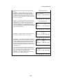
•Screen one
1. View Date & Time
The date and time can be viewed on both screens. To change the displayed order of the date,
(Date/Month/Year), (Month/Date/Year) or (Year/Month/Date), see Chapter 7 “PARAMETERS
SETTING MODE”.
To set the date and time, see Chapter 8 “CHECK AND ADJUSTMENT” .
2.
Adjustment the contrast of the display
This enable you to adjust the contrast of the display.
Press the [F1] or [ F2] key to adjust the contrast.
3.
Turn the display back light ON/OFF
When the back light is OFF, the light bulb icon is dark.
To turn the back light ON, press the [F3] key. Press [F3] again to turn the back light OFF.
OFF
4.
ON
Reticle illumination ON (1 to 9 ) / OFF
Press the [F4] key to turn the reticle illumination ON. Select the brightness by pressing numeric
key To turn the illumination OFF, press [F4] key again.
1 to 9
ON
OFF
5.
View free memory
The amount of free memory for the internal memory can be displayed.
Press the [F5] key to view free memory.
The icon shows the size of the amount of free internal memory.
Card model can display free memory for the Internal Memory and Card memory.
Internal Memory
Card Memory
188KByte
16MB
Internal Memory
15504KByte
188KByte
Card model
Refer to Chapter 5 -MEMORY MANAGE MODE, for further options and instructions.
1-8
1 NOMENCLATURE AND FUNCTIONS
• Screen two
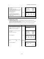
6. Electric circular level graphic display
Electric circular level can be displayed by graphic. This function is good for level the instrument
when the circular level is difficult to see directly.
Press the [F6] key to get to Screen 2 on the display.
Press the [F1] key to display the graphic.
In the displays of reverse side, the graphic bubble moves in reverse.
X:00°00'00"
Y:00°00'00"
X:
Y:
Rotate the leveling screws while observing the display.
After leveling, press [F1]. The display changes to the previous mode.
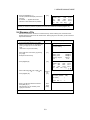
7.
Set audio mode
The light acceptance quantity level (Signal level) is displayed in this mode.
When reflected light from the prism is received, a buzzer sounds. This function is good for easy
collimation when the target is difficult to find.
Press the [F6] key to get to Screen 2 on the display then press the [F2] key on screen 2.
The received return signal level is displayed with bar graph as follows.
ast and simple
No light acceptance
Minimum quantity level
Maximum quantity level
(1) To stop the buzzer, refer to Chapter 7 “PARAMETERS SETTING MODE”.
(2) Also, it is possible to display the signal level in Distance Measuring Mode.
8.
Setting Temperature, Pressure, Atmospheric correction value (PPM), Prism constant value
(PSM)
Press the [F6] key to get to Screen 2 on the display then press the [F3] key on screen 2.
The temperature, pressure, PPM, and PSM can be viewed.
Refer to Chapter 9 “SETTING THE PRISM CONSTANT VALUE” and Chapter 10 “SETTING
ATMOSPHERIC CORRECTION” , for further instructions.
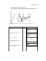
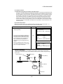
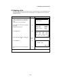
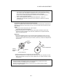
9.
Point guide ( Only for Point guide type)
This feature is most useful when doing stake out work.The Point Guide's red LEDs on the GTS600 Series telescope assist the rod person in getting on-line. The Point Guide feature is fast and
simple to use.
• Operating Instructions
Press the [F6] key to get to Screen 2 on the display then press the [F4] key to turn ON the
Point Guide LEDs. The Point guide icon on the display will become bright when turned ON.
Looking the objective lens of the telescope, the right LED will blink and the left LED will stay lit.
1-9
1 NOMENCLATURE AND FUNCTIONS
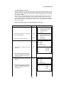
The Point Guide should be used within a distance of
100 meters (328 ft.). The quality of its results will
depend on the weather conditions and the user's
eyesight.
The goal of the rod person is to look at both LEDs
on the instrument and move the prism on-line until
both LEDs become equally bright . If the solid LED
is brighter, move to the right. If the blinking LED is
brighter, move to the left.
10. Laser Plummet ( Only for Laser Plummet type)
Laser plummet option will help you to center the instrument easily onto the measurement point.
Press the (•) key to view the instrument options. Since there are two screens of options, press
[F6](1 • ) soft key to view the next screen.
Press the [F5]key to turn on/off of laser plummet option.
Laser plummet icon will change as follows.
Symbol mark while the laser is emitting.
The following symbol mark will indicate that the laser is emitting.
V : 87°55'45"5
HR: 180°44'12"5
The symbol mark will blink while the laser
plummet is working
SD HD NEZ 0SET HOLD P1
Laser Plummet auto-cut off function
The laser plummet will be turned off automatically after 1 to 99 minutes (Default:3 minutes). It is
also possible to stop the auto-cut off function.
Refer to the next page and Chapter 7 “PARAMETERS SETTING MODE” to change the time or to
invalidate the function.
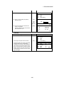
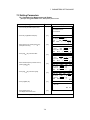
1.6 Auto Power Off
If no key operation is given for the setting time(1 to 99 minutes), the power turns off automatically.
To set the Auto Power Off function OFF/ON(1 to 99 minutes), refer to Chapter 7 “PARAMETERS
SETTING MODE”.
To set the time of auto power off in parameters setting mode, after selecting [ON], input the time by
numeric key.
1-10
1 NOMENCLATURE AND FUNCTIONS
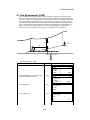
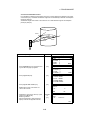
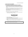
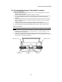
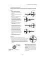
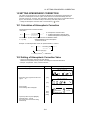
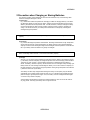
1.7 Automatic Focusing (Only for Automatic Focusing model)
The automatic focusing is useful for rapid surveying.
Press the automatic focusing key after sighting a target by using with the sighting collimator. The
automatic focusing will start with a “bip” sound.
The automatic function will be completed with two “bip” sounds. If the automatic focusing is not
accomplished, a beep will be heard.
Sighting collimator
Automatic focusing key
Diopter ring
Focusing knob
(For manual focus)
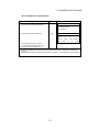
Note:
1) The focusing knob will turn automatically when the instrument is powered on or the automatic
focusing is working.
Do not touch the knob while it turns.
2) EDM, the reticle illumination and the point guide are turned off automatically while the
automatic focusing is working.
3) The auto focusing may be completed roughly when the contrast with the target and its
circumference is low. In this case, focus the target manually by turning the focusing knob.
4) If there is an object that has higher contrast than a prism or a target near the horizontal hair
line in the field of view, the instrument may focus to that object.
5) If a strong light comes into the eyepiece, the auto focusing may not be completed.
6) Before operating, the diopter adjustment should be done by turning the diopter ring so that
the cross hairs are clearly observed.
7) If parallax is created between the cross hairs and the target, focusing is incorrect. This
adversely affects precision in surveying. Eliminate the parallax by turning the focusing knob
or using the diopter adjustment.
8) The automatic focusing adjustment can be set up by software.
See next section to adjust the focus.
1-11
1 NOMENCLATURE AND FUNCTIONS
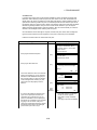
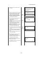
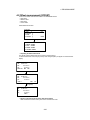
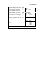
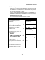
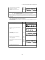
Adjustment of automatic focusing
If the automatic focusing is incorrect though the diopter adjustment is complete, adjust the
automatic focusing.
The automatic focus position adjustment can be easily set up by software as follows.
Operating procedure
Option
Display
Prog Std Mem Com
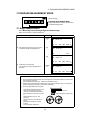
1 Press the [F5](Adj) key from the main menu
[F5]
icons.
2 Press the [F4](Auto Focus) key.
[F4]
Adjustment
F1 V0/Axis (Measurement)
F2 V0/Axis (Constant list)
F3 Date Time
F4 Auto Focus
Adj. Auto Focus (1/2)
Adjust diopter.
And press [AF] key.
EXIT
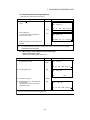
3 Adjustment the diopter by turning the diopter
ring so that the cross hairs are clearly
observed.
5
6
AF
Adjust
diopter
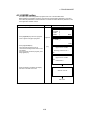
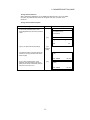
4 Press the [F6](AF) key.
Auto focusing will start.
Look into the telescope and confirm whether
the focusing is completely done or not. If not,
focus the target with the focusing knob
manually.
Press the [F6](SET) key to finish the
adjustment.
The screen will return to the main menu icons.
Adj Para
[F6]
Focus
manually
Adj. Auto Focus (2/2)
Focus with the manual knob
if out of focus.
Then press [SET] key
EXIT BACK
SET
[F6]
● Press the [F2](BACK) key to return to previous screen (Step three).
1-12
2 PREPARATION FOR MEASUREMENT
2 PREPARATION FOR MEASUREMENT
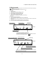
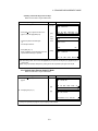
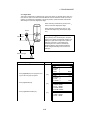
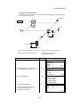
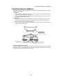
2.1 Power Connection
(unnecessary if on-board Ni-MH battery BT-50Q is used)
See below for connecting the external battery pack.
• Battery pack BT-3Q
Power cord , PC-5 is used.
• Large capacity battery pack BT-3L
Power cord PC-6 is used.
Connector ends
PC-5
BT-3Q
PC-5
PC-6
BT-3L
2-1
PC-6
2 PREPARATION FOR MEASUREMENT
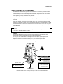
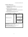
2.2 Setting Instrument Up For Measurement
Mount the instrument to the tripod. Level and center the instrument precisely to insure the best
performance. Use tripods with a tripod screw of 5/8 in. diameter and 11 threads per inch, such as
the Type E TOPCON wide- frame wooden tripod.
Reference: Leveling and Centering the Instrument
1. Setting up the Tripod
First, extend the extension legs to suitable lengths
and tighten the screws on their midsections.
2. Attaching the Instrument on the Tripod
Head
Place the instrument carefully on the tripod head
and slide the instrument by loosening the tripod
screw. If the plumb bob is positioned right over the
center of the point, slightly tighten the tripod
screw.
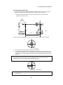
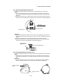
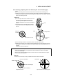
3. Roughly Leveling the Instrument by Using
the Circular Level
1 Turn the leveling screws A and B to move the
bubble in the circular level. The bubble is now
located on a line perpendicular to a line
running through the centers of the two leveling
screws being adjusted.
Leveling screw C
regardless of
Leveling
screw A
Leveling screw B
2
Rotate the instrument 90¡ (100g) around its
vertical axis and turn the remaining leveling
screw or C to center the bubble once more.
Leveling screw C
90
3
Repeat the procedures 1 and 2 for each 90¡
(100g) rotation of the instrument and check
whether the bubble is correctly centered for all
four points.
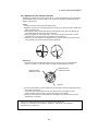
5. Centering by Using the Optical Plummet
Telescope
Adjust the eyepiece of the optical plummet
telescope to your eyesight.
Slide the instrument by loosening the tripod
screw, place the point on the center mark, and
then tighten the tripod screw. Sliding the
instrument carefully not to rotate that allows you
to get the least dislocation of the bubble.
Point
2
Turn the leveling screw C to bring the bubble
to the center of the circular level.
4. Centering by Using the Plate Level
1 Rotate the instrument horizontally by using
the Horizontal motion/clamp screw and place
the plate level parallel with the line connecting
leveling screws A and B, and then bring the
bubble to the center of the plate level by
turning leveling screws A and B.
Center mark
6. Completely Leveling the Instrument
Leveling the instrument precisely in a similar way
to 4. Rotate the instrument and check to see that
the bubble is in the center of the plate level
regardless of telescope direction, then tighten the
tripod screw hard.
Leveling
screw A
Leveling
screw B
2-2
2 PREPARATION FOR MEASUREMENT
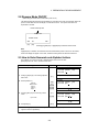
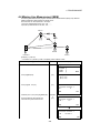
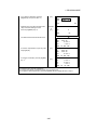
2.3 Power Switch Key ON
1 Confirm the instrument is leveled.
2 Turn the power switch ON.
Power switch key ON
GTS-600 series
2001-07-10 15:30:40
Battery Power Remaining Display
Prog Std Mem Com
Adj Para
Main menu
• Confirm the battery power remaining on the display. Replace with charged battery or charge when
battery level is low. see Section 2.4“Battery Power Remaining Display” .
2-3
2 PREPARATION FOR MEASUREMENT
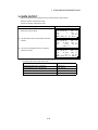
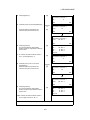
2.4 Battery Power Remaining Display
Battery power remaining display indicates the power condition.
Battery power remaining display
2001-07-10 15:30:40
Measurement is possible.
Prog Std Mem Com
Adj Para
The power is poor. The battery
should be recharged or replace the
battery.
Blinking
Measurement is impossible.
Need to recharge or replace
the battery.
* Battery power remaining display is omitted in this manual.
Note:
. on the environmental conditions such as
1) The battery operating time will vary depending
ambient temperature, charging time, the number of times of charging and discharging etc. It
is recommended for safety to charge the battery beforehand or to prepare spare full charged
batteries.
2) For general usage of the battery, see Chapter 12 POWER SOURCE AND CHARGING .
3) The battery power remaining display shows the power level regarding to the measurement
mode now operating.
The safety condition indicated by the battery power remaining display in the angle
measurement mode does not necessarily assure the battery s ability to be used in the
distance measurement mode.
It may happen that the mode change from the angle mode to the distance mode will stop the
operation because of insuf cient battery power for the distance mode which consumes more
power than angle mode.
Note that the EDM unit is working when the pictogram for zero set and the battery power
remaining display shown at the power ON, which shows as an easy battery check before use
4) When the measurement mode is changed, it rarely may happen that the Battery Power
Remaining Display will decrease or increase two steps momentarily because of the
accuracy of the battery checking system is rough. It is not trouble with the instrument.
2-4
2 PREPARATION FOR MEASUREMENT
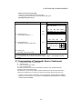
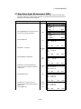
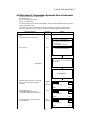
2.5 Main Menu Contains
The main menu contains as following items.
Select the menu by pressing soft keys ([F1]~[F6]).
2001-07-10 15:30:40
Prog
Std
Mem
Com
Adj
Para
PARAMETERS SETTING MODE
The PARAMETERS SETTING MODE settled
is memorized even power is off.
(see Chapter 7 PARAMETERS SETTING
MODE .)
ADJUSTMENT MODE
This mode is used for checking and adjustment.
● Adjustment of compensation systematic errors of
instrument
● Showing compensation values of systematic errors of
instrument
● Setting Date & Time
● Setting instrument constant value
(see Chapter 8 CHECK AND ADJUSTMENT .)
COMMUNICATION MODE
This mode is used.) for follows
● Setting of PROTOCOL
● Data le in/out
(see Chapter 6 COMMUNICATION MODE .)
MEMORY MANAGE MODE
This mode is used for follows
● Displaying le memory status
● Protecting/Erasing/Renaming
● Initializing a le.
(see Chapter 5 MEMORY MANAGE MODE
STANDARD MEASUREMENT MODE
This mode is used for follows
● Angle measurement
● Distance measurement
● Coordinate measurement
(see Chapter 3 STANDARD MEASUREMENT MODE .)
PROGRAM MODE ( APPLICATION MEASUREMENT)
This mode is used for follows.
1. Setting a direction angle for horizontal orientation (BS)
2. Retaining a Coordinate (STORE-NEZ)
3. Remote elevation measurement (REM)
4. Missing line measurement (MLM)
5. Repetition angle measurement (REP)
6. Layout (LAYOUT)
7. Line measurement (LINE)
8. Offset measurement (OFFSET)
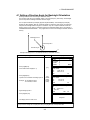
9. Application software Loader option.(LOADER)
(see Chapter 4 PROGRAM MODE .)
2-5
2 PREPARATION FOR MEASUREMENT
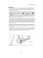
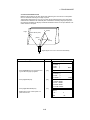
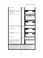
2.6 Vertical and Horizontal Angle Tilt Correction
When the tilt sensors are activated, automatic correction of vertical and horizontal angle for
mislevelment is displayed.
To ensure a precise angle measurement, tilt sensors must be turned on. The display can also be
used to fine level the instrument. If the (TILT OVER) display appears the instrument is out of automatic compensation range and must be leveled manually.
Zenith
Standing axis
Standing axis
Zenith
Inclination of the standing
axis in the Y direction
Inclination of the standing
axis in the X direction
Horizontal
Trunion axis
• GTS-600 compensates both the vertical angle and the horizontal angle readings due to inclination
of the standing axis in the X and Y directions .
• For more information about dual axis compensation, see Chapter “APPENDIX” .
When the instrument tilted over correction range.
X:
Y:
Rotate the leveling screws and level the
instrument.
After leveling, the display returns to the
previous mode.
X:00¡00’00"
Y:00¡00’00"
• The display of Vertical or Horizontal angle is unstable when instrument is on an unstable stage or
a windy day. You can turn off the auto tilt correction function of V/H angle in this case. To set TILT
correction mode ON/OFF, refer to next page or Chapter 7 “PARAMETERS SETTING MODE” .
2-6
2 PREPARATION FOR MEASUREMENT
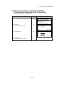
• Setting Tilt Correction by Soft Key
Enable you to select tilt ON/OFF function on page 2.
The setting performed here will be memorized after powering OFF.
[Example] Setting X,Y Tilt ON
Operating procedure
Option
1 Press [F6] key to get the function page 2.
V : 87 55'45"
HR: 180 44'12"
[F6]
2 Press [F5](TILT) key.
Current setting is displayed. *1
Display
[F5]
SD HD
NEZ 0SET
REC HSET R/L V/%
TILT ON (V)
ON-1
3 Press [F2](ON-2) key.
The display shows tilt correction value.
HOLD P1
TILT P2
ON-2
OFF
ESC
[F2]
X:00 00'00"
Y:00 00'00"
4 Press [F1] key.
The display returns previous mode.
[F1]
*1) Pressing [F6](ESC) key, the display returns previous mode.
● The setting performed here will be interlocked with. setting in Chapter 7 PARAMETERS SETTING
MODE
2.7 Compensation of Systematic Error of Instrument
1) Error of vertical axis (X,Y tilt sensor offset)
2) Collimation error
3) Error of vertical angle 0 datum
4) Error of horizontal axis
The above mentioned errors can be compensated by software, which calculated internally
according to each compensation value.
Also these errors can be compensated by software collimating one side of the telescope that is
carried out to delete the error by turning in normal and reverse both sides of telescope so far.
• To adjust or reset the above compensation value, see Chapter 8 “CHECK AND ADJUSTMENT” .
• Enable you to stop this function, see Chapter 7 “PARAMETERS SETTING MODE” or Chapter 8
“CHECK AND ADJUSTMENT” .
2-7
2 PREPARATION FOR MEASUREMENT
2.8 Resume Mode ON/OFF
(Memorizing the measurement mode when power is off.)
The Resume Mode will memorize the last display or mode when the power is turned OFF. When the
power is turned back ON, the last display or mode will be shown . This option saves time and
keystrokes in the field.
Power switch key OFF
Power off
Resume mode
OFF
ON
[F1]
[F2]
ESC
Pressing [F1](OFF) key or [F2](ON) key, select the resume mode.
Note:
If [F2](ON) key is selected, the instrument must be leveled before power is ON. If it is not leveled,
the tilt over display will appear. In this case, rotate the leveling screw and level the instrument.
2.9 How to Enter Numerals and Alphabet Letters
This enables you to enter numerals or alphabet letters such as the file name.
[Example] Enter “HIL 104” to rename the file name.
Operating procedure
Option
Display
Rename
Old name [TOPCON .DAT]
]
New name [
Alpha
1 Press [F1](Alpha) key to be entering alphabet
2 Enter Alphabets. *1)
Input “H”
Move cursor
Input “I”
Input “L”
Input “ ”
SPC
[F1]
letter mode.
[9][9]
[F4]
[9][9][9]
[4][4][4]
[3][3][3]
3 Press [F1](Num) key to be entering numeric
[F1]
mode.
[1][0][4]
Rename
Old name [TOPCON
New name [HIL
Num
.DAT]
]
SPC
Rename
Old name [TOPCON .DAT]
New name [HIL 104 ]
Input “104”
Alpha
4 Press [ENT] key.
SPC
[ENT]
*1)When entering a alphabet in the same key consecutively, press [F4]( A) key to move the cursor to the
right then enter the alphabet key.
2-8
2 PREPARATION FOR MEASUREMENT
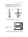
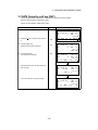
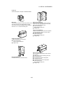
2.10 Data Memory Card (Only for Card model)
• How to insert a data memory card
Card cover
Card guide
Card cover
lever
Data memor
card
1 Pull the card cover lever to open the card cover.
2 Insert a memory card until the card guide is up.
Make sure the card is inserted firmly in the correct direction.
3 Close the card cover.
• How to extract a memory card
1 Pull the card cover lever to open the card cover.
2 Pull down the card guide.
Note: Hold the card with your hand to protect the card against falling.
3 Extract the memory card.
4 Close the card cover.
2-9
Card guide
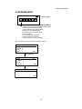
3 STANDARD MEASUREMENT MODE
3 STANDARD MEASUREMENT MODE
2001-07-10 15:30:40
[Press [F2] key.]
STANDARD MEASUREMENT MODE
Angle measurement, Distance measurement,
Coordinate measurement .
Prog Std Mem Com Adj Para
3.1 Angle Measurement
3.1.1 Measuring Horizontal Angle Right and Vertical Angle
Make sure the mode is in Angle measurement.
Operating procedure
1 Collimate the 1st target (A).
Operation
Collimate
A
Display
V : 87°55'45"
HR: 180°44'12"
SD
2 Set horizontal angle of target A at 0 00’ 00".
Press [F4](0 set)key and [F6](SET) key.
[F4]
HD
NEZ
0SET
H-0SET
HR: 00°00'00"
ESC
[F6]
V :
HR:
SD
3 Collimate the 2nd target (B).
The required H/V angle to target B will be
displayed.
Collimate
B
HOLD P1
SET
87°55'45"
00°00'00"
HD
NEZ
0SET
HOLD P1
0SET
HOLD P1
V : 87°55'45
HR: 123°45'50
SD
HD
NEZ
Reference : How to Collimate
1
2
3
Point the telescope toward the light. Turn the diopter ring and adjust the diopter so that the cross
hairs are clearly observed.
(Turn the diopter ring toward you rst and then backward to focus.)
Aim the target at the peak of the triangle mark of the sighting collimator. Allow a certain space
between the sighting collimator and yourself for collimating.
Focus the target with the focusing knob.
*If parallax is created between the cross
hairs and the target when viewing
vertically or horizontally while looking
into the telescope, focusing is incorrect
or
diopter adjustment is poor. This
adversely
affects precision in measurement or
survey
Eliminate the parallax by carefully
focusing
and using diopter adjustment.
Focusing knob
Telescope eyepiece (Diopter ring)
3-1
3 STANDARD MEASUREMENT MODE
3.1.2 Switching Horizontal Angle Right/Left
Make sure the mode is Angle measurement.
Operating procedure
Operation
1 Press [F6]( )key to get the function as on
Display
V : 87°55'45"
HR: 120°30'40"
page 2.
[F6]
2 Press [F3](R/L) key.
[F3]
The mode Horizontal angle Right (HR)
switches to (HL) mode.
SD
HD
REC HSET
NEZ
R/L
0SET HOLD P1
V/% TILT P2
V : 87°55'45"
HL: 239°29'15"
REC HSET
R/L
V/%
TILT P2
3 Measure the target in the same manner as
HR mode.
● Every time pressing [F3](R/L) key is pressed, HR/HL mode switches.
Note: It is possible that the R/L switching is prohibited (R/L Rock). To set the R/L rock, see Chapter 7
PARAMETERS SETTING MODE .
3.1.3 Measuring from the Required Horizontal Angle
1) Setting by Holding the Angle
Make sure the mode is angle measurement..
Operating procedure
1 Set the required horizontal angle, using
Horizontal tangent screw
Operation
Display
angle
Display
V :
HR:
SD
2 Press [F5](HOLD) key.
[F5]
90°10'20"
70°20'30"
HD
NEZ
0SET
Holding
HR: 70°20'30"
ESC
3 Collimate the target.*1)
HOLD P1
REL
Collimate
4 Press [F6](REL) key to nish holding the
[F6]
horizontal angle.
The display turns back to normal angle
measurement mode.
V :
HR:
SD
*1)To return to the previous mode, press [F1](ESC) key.
3-2
90°10'20"
70°20'30"
HD
NEZ
0SET
HOLD P1
3 STANDARD MEASUREMENT MODE
2) Setting a Horizontal Angle from the Keys
Make sure the mode is Angle measurement.
Operating procedure
1 Collimate the target.
Operation
Collimate
2 Press [F6]( ) key to get the function as on
[F6]
page 2, and press [F2](HSET) key.
Display
V : 90°10'20"
HR: 120°30'40"
SD HD NEZ 0SET HOLD
REC HSET R/L V/% TILT
P1
P2
[F2]
3 Input the required horizontal angle.
Input
value
*1)
For example:70°20’30"
H-SET
HR:
H-SET
HR:70.203
EXIT
4 Press [ENT] key. *2)
When completed, normal measuring from the
required Horizontal angle is possible.
[ENT]
V :
HR:
SD
BS
90°10'20"
70°20'30"
HD
NEZ
0SET
HOLD P1
*1)To revise wrong value, move cursor with [F6](BS) key, or input from the beginning by [F1](EXIT) key to
correct value.
*2)With wrong input value(for example 70’), setting will not be completed. Input again from step 3.
3.1.4 Vertical Angle Percent Grade(%) Mode
Make sure the mode is Angle measurement.
Operating procedure
Operation
1 Press [F6]( ) key to get the function as on
V : 90°10'20"
HR: 120°30'40"
page 2.
[F6]
2 Press [F4](V/%) key. *1)
Display
[F4]
SD HD NEZ 0SET
REC HSET R/L V/%
HOLD
TILT
V%:
-0.30
%
HR: 120 30'40"
REC HSET R/L V/% TILT P2
*1) Every time pressing the [F4](V/%) key, the display mode switches.
3-3
P1
P2
3 STANDARD MEASUREMENT MODE
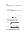
3.2 Distance Measurement
3.2.1 Setting of the Atmospheric Correction
When setting the atmospheric correction, obtain the correction value by measuring the temperature and pressure.
Setting the atmospheric correction is in the STAR key (•••) mode, see Chapter 10 “SETTING
ATMOSPHERIC CORRECTION” .
3.2.2 Setting of the Correction for Prism Constant
Topcon's prism constant value is 0. Set correction for prism at 0. If the prism is of another manufacture, the appropriate constant shall be set beforehand.
Setting the prism constant value is in the STAR key (•••) mode, see Chapter 9 “SETTING THE
PRISM CONSTANT VALUE” .
3.2.3 Distance Measurement (Continuous Measurement)
Make sure the mode displays angle measurement.
Operating procedure
Operation
1 Collimate the center of prism.
Display
V : 90°10'20"
HR: 120°30'40"
SD
2 Press [F1](SD) key or [F2]( HD )key.
[F2]
*1), 2)
[Example] Horizontal distance mode
HD
NEZ
0SET
HOLD
P1
V : 90°10'20"
HR: 120°30'40" PSM
0.0
HD:
< PPM
0.0
VD:
(m) *F.R
MEAS MODE VH
SD NEZ P1
V : 90°10'20"
HR: 120°30'40"
PSM
0.0
HD:
716.661 PPM
0.0
VD:
4.001
(m) *F.R
MEAS MODE VH
SD NEZ P1
The result are shown*3) ~ *6)
*1)The following characters will be shown on the 4th line right hand corner of the display to represent
measurement mode.
F=Fine; C=Coarse; T=Tracking; R=Continuous (Repeat); S=Single; N=N time
*2)When EDM is working, the " *" mark appears in the display.
*3)The result is shown with buzzer sound.
*4)Measurement may repeat automatically if the result is affected by shimmer etc..
*5)To change single measuring, press [F1](MEAS) key.
*6)To return to the angle measurement mode, press [F3](VH) key.
3-4
3 STANDARD MEASUREMENT MODE
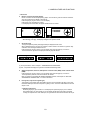
3.2.4 Distance Measurement (Single/N-times Measurement)
When presetting the number of times, the instrument measures the distance as the setting times
and the average distance will be displayed.
When presetting the number of times as 1, it does not display the average distance, because of
single measurement. It has been set at single measurement at factory.
1) Setting the number of times
Confirm the angle measurement mode.
Operating procedure
Operation
1 Press [F1](SD) or [F2](HD) key.
Display
V : 90°10'20"
HR: 120°30'40"
SD
[F2]
[F6]
2 Press [F6]( ) key to get the function page as
HD
NEZ
0SET
HOLD P1
V : 90°10'20"
HR: 120°30'40"
PSM
0.0
HD:
PPM
0.0
VD:
(m) F.R
MEAS MODE VH SD NEZ P1
REC
SO MEAN
m/ft
P2
2.
3 Press [F3](MEAN) key.
[F3]
Average times
N:0
4 Input the setting the number of times, and
[F4][ENT]
press [ENT] key. *1)
[Example] 4 times
N-times measurement starts.
EXIT
BS
V : 90°10'20"
HR: 120°30'40"
PSM
HD:
<
PPM
VD:
(m)
REC SO
MEAN
m/ft
0.0
0.0
*F.N
P2
2) Measuring Method
Confirm the angle measurement mode.
Operating procedure
1 Collimate the center of the prism.
Operation
Collimate
Display
V : 90°10'20"
HR: 120°30'40"
SD
2 Select the measurement mode by pressing
[F1](SD) or [F2](HD) key.
Example:Horizontal distance
N-times measurement starts.
[F2]
3-5
HD
NEZ
0SET
HOLD P1
V : 90°10'20"
HR: 120°30'40"
PSM
0.0
HD:
PPM
0.0
VD:
(m) F.N
MEAS MODE VH SD NEZ P1
3 STANDARD MEASUREMENT MODE
V : 90°10'20"
HR: 120°30'40"
PSM
0.0
HD:
54.321
PPM
0.0
VD:
1.234
(m) *F.N
MEAS MODE VH
SD
NEZ P1
The average value is displayed following with
buzzer sound and “ * ” mark disappears.
V :
90°10'20"
HR: 120°30'40"
PSM
0.0
HD:
54.321
PPM
0.0
VD:
1.234
(m) F.N
MEAS MODE VH
SD NEZ P1
● Press [F1](MEAS) key for re-measuring after the measurement in held.
● To return to the continuous measuring , press [F1](MEAS) key twice.
● To return to the angle measuring mode , press [F3](VH) key.
3-6
3 STANDARD MEASUREMENT MODE
3.2.5 Fine/ Tracking / Coarse Measuring Mode
•Fine mode :
This is a normal distance measuring mode.
Measurement time
0.2mm mode :
approx.2.8 seconds
1 mm mode :
approx.1.2 seconds
The unit to be displayed is 0.2mm or 1mm. (0.001ft or 0.005ft)
•Tracking mode :
This mode measures in shorter time than in fine mode.
Use this mode for stake out measurement. It is very useful when tailing
the moving object or carrying out stake-out work.
Measurement time :
approx. 0.4 seconds
The unit to be displayed is 10mm. (0.02ft)
•Coarse mode :
This mode measures in shorter time than in fine mode.
Use this mode for the objects which may be slightly unstable.
Measurement time :
approx. 0.7 seconds
The unit to be displayed is 1mm. (0.005ft)
Operating procedure
1 Collimate the center of prism.
Operation
Collimate
Display
V: 90°10'20"
HR: 120°30'40"
SD
2 Select the measurement mode by pressing
[F1](SD) or [F2](HD) key.
Example:Horizontal distance
Measuring starts.
3 Press [F2](MODE) key , the mode changes
to Coarse mode.
Press [F2](MODE) key again, the mode
changes to Tracking mode. *1)
[F2]
[F2]
[F2]
HD
NEZ
HOLD P1
V : 90°10'20"
HR: 120°30'40"
PSM 0.0
HD:
<
PPM 0.0
VD:
(m) *F.R
MEAS MODE VH
SD NEZ P1
V : 90°10'20"
HR: 120°30'40"
HD:
VD:
MEAS MODE VH
*1) Every time pressing [F2](MODE) key, the mode will be changed in procedure 3 .
3-7
0SET
PSM
PPM
(m)
SD NEZ
0.0
0.0
T.R
P1
3 STANDARD MEASUREMENT MODE
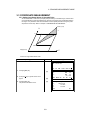
3.2.6 Stake Out (S-O)
The difference between the measured distance and the distance preset is displayed.
The displayed value = Measured distance - Standard (Preset) distance
• Stake out operation can be performed for horizontal distance (HD), relative elevation (VD) or
slope distance (SD)
[Example: Relative elevation]
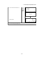
Operating procedure
Operation
1 Press [F6](P1) key in the distance measuring
mode to get the function as in page 2.
[F6]
2 Press [F2](S-O) key and press [ENT] key.
3 Enter the relative elevation for stake out, and
press [ENT] key.
The measuring starts.
[F2]
[ENT]
Enter
value
[ENT]
4 Collimate the target (Prism).
The difference between the measured
distance and the standard distance is
displayed.
Display
V : 90°10'20"
HR: 120°30'40"
PSM
HD:
PPM
VD:
(m)
MEAS MODE VH
SD
NEZ
REC
SO
MEAN
m/ft
0.0
0.0
F.R
P1
P2
SO
HD : 0.000
VD :
EXIT
V :
90°10'20"
HR : 120°30'40"
HD :
<
dVD :
REC
SO MEAN
BS
PSM
0.0
PPM
0.0
(m) *F.R
m/ft
P2
V : 90°10'20"
HR: 120°30'40"
PSM
0.0
HD:
<
PPM
0.0
VD:
(m) *F.N
REC SO
MEAN
m/ft
P2
● To return to normal distance measurement mode, reset the standard distance to 0 or turn the power
switch off (Resume mode:OFF) once.
3-8
3 STANDARD MEASUREMENT MODE
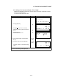
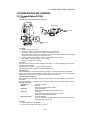
3.3 COORDINATE MEASUREMENT
3.3.1 Setting Coordinate Values of Occupied Point
Set the coordinates of instrument (occupied point) according to coordinate origin, and the instrument automatically converts and displays the unknown point (prism point) coordinates following
the origine. It is possible to retain the coordinates of the occupied point after turning the power
off (Resume mode :OFF). Refer to Chapter 7 “PARAMETERS SETTING MODE” .
Prism (n,e,z)
N
z
n
Inst.PointC
Origin(0,0,0)
E
e
Confirm the angle measurement mode.
Operating procedure
Operation
Display
V : 90°10'20"
HR: 120°30'40"
SD
1 Press [F3](NEZ) key.
[F3]
2 press [F6]( ) key to get the function as on
page 2.
3 Press [F5](SET) key.
The previous data will be shown.
[F6]
[F5]
3-9
N :
E :
Z :
HD
NEZ
0SET
HOLD P1
<
PSM
0.0
PPM
0.0
(m) *F.R
MEAS MODE VH
SD
HD
P1
REC HT MEAN m/ft SET P2
Setting occ. point
N :
12345.6700
12.3400
E :
Z :
10.2300
EXIT
BS
3 STANDARD MEASUREMENT MODE
4 Input new data and press [ENT] key. *1)
N coord.
[ENT]
E coord.
[ENT]
Z coord.
[ENT]
Setting occ. point
N : 0.0000
E : 0.0000
Z : 0.0000
EXIT
BS
Complete
N :
E :
Z :
Measuring starts.
REC
*1)To cancel the setting, press [F1](EXIT) key.
3-10
<
HT
MEAN
PSM
PPM
(m)
m/ft SET
0.0
0.0
*F.R
P2
3 STANDARD MEASUREMENT MODE
3.3.2 Setting of the Instrument Height / Prism Height
Measure the coordinates by entering the instrument height / prism height, coordinates of unknown
point will be measured directly.
Confirm the angle measurement mode.
Operating procedure
Operation
Display
V : 90°10'20"
HR: 120°30'40"
SD
1 Press [F3](NEZ) key.
[F3]
2 Press [F6]( ) key from the coordinate
measurement mode to get the function as in
page 2.
3 Press [F2](HT) key.
Previous data will be shown.
[F6]
HD
NEZ
key.*1)
5 Input prism height, and press [ENT] key.
HOLD P1
N :
E :
Z :
PSM
0.0
PPM
0.0
(m) *F.R
MEAS MODE VH
SD
HD
P1
REC
HT MEAN m/ft SET
P2
[F2]
Inst. Ht
R. Ht
EXIT
4 Input instrument height, and press [ENT]
0SET
:
:
1.230 m
1.340 m
BS
Inst. HT
[ENT]
Prism HT
[ENT]
The display returns to coordinate measuring
mode.
N :
E :
Z :
REC
*1)To cancel the setting, press [F1](EXIT) key.
3-11
HT
MEAN
PSM
0.0
PPM
0.0
(m) *F.R
m/ft SET P2
3 STANDARD MEASUREMENT MODE
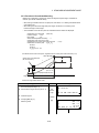
3.3.3 Execution of Coordinate Measuring
Measure the coordinates by entering the instrument height and prism height, coordinates of
unknown point will be measured directly.
• When setting coordinate values of occupied point, see Section 3.3.1“Setting Coordinate Values
of Occupied Point” .
• When setting the instrument height and prism height, see Section 3.3.2“Setting of the
Instrument Height / Prism Height” .
• The coordinates of the unknown point are calculated as shown below and displayed:
Coordinates of occupied point : (N0,E0,Z0)
Instrument height : Inst.h
Prism height
: R.h
Vertical distance(Relative elevation) : z
Coordinates of the center of the prism,
originated from the center point of the instrument
Coordinates of unknown point : (N1,E1,Z1)
N1=N0+n
E1=E0+e
Z1=Z0+Inst.h+z - P.h
: (n,e,z)
Coordinates of the center of the prism, originated from the center point of the instrument (n,e,z)
Center point of the instrument
(No, Eo, Zo+Inst.h)
R.h
SD
VD
z
ument
Unknown point
(N1, E1, Z1)
Inst.HT
Occupied point (No, Eo, Zo)
Origin (o, o, o)
HD
Confirm the angle measurement mode.
Operating procedure
Operation
1 Set coordinates values of occupied point
2
and instrument/prism height. *1)
Set the direction angle of known point A. *2)
3 Collimate target B.
4 Press [F3](NEZ) key.*3)
Measuring starts.
Display
V : 90°10'20"
HR: 120°30'40"
Set
direction
angle
SD
HD
NEZ
0SET
HOLD P1
Collimate
[F3]
MEAS
3-12
<
N :
E :
Z :
MODE
VH
PSM
0.0
PPM
0.0
(m) *F.R
SD
HD P1
3 STANDARD MEASUREMENT MODE
The result will be shown.
N : 12345.6789
E : -12345.6789
Z :
10.1234
MEAS
MODE
VH
PSM
0.0
PPM
0.0
(m) *F.R
SD
HD
P2
*1) In case the coordinate of instrument point is not entered, (0,0,0) will be used as the default for the
instrument point.
The instrument height will be calculated as 0 when the instrument height is not entered.
The prism height will be calculated as 0 when the prism height is not set.
*2) Refer to Section 3.1.3 Measuring from the Required Horizontal Angle or Section 4.1 Setting a Direction
Angle for Backsight Orientation .
*3) Pressing [F1](MEAS) key, the measurement mode (Continuous measuring/ N-time measuring)
changes.
Pressing [F2](MODE) key, the measurement mode (FINE/ COARSE/TRACKING) changes.
● To return to the normal angle or distance measuring mode, press [F6](P ) key to return to the function
as on page 1 and press [F3](VH),[F4](SD) or [F5](HD) key.
3-13
3 STANDARD MEASUREMENT MODE
3.4 DATA OUTPUT
Result of measurement is transferred from the GTS-600 series to Data Collector.
[Example: Distance measurement mode]
Confirm the distance measurement mode.
Operating procedure
Display
1 Operate the data collector to measure the distance.
Measurement will be started.
2 The result will be shown and transferred to the Data
Collector.
3 The mode will automatically return to the distance
measurement mode.
V: 90°10'20"
HR: 120°30'40"
PSM
0.0
HD:
<
PPM
0.0
VD:
(m) *F.R
MEAS MODE VH
SD NEZ P1
V :
90°10'20"
HR: 120°30'40"
PSM
0.0
HD:
10.1234
PPM
0.0
VD:
1.234
(m) *F.R
REC > > >
V :
90°10'20"
HR: 120°30'40"
PSM
0.0
HD:
10.1234
PPM
0.0
VD:
1.234
(m) *F.R
MEAS MODE VH
SD NEZ P1
The following data will be output at each mode.
Mode
.
Output
Angle mode ( V,HR or HL) ( V in percent)
V, HR (or HL)
Horizontal distance mode (V,HR, HD, VD)
V, HR, HD, VD
Slope distance mode (V, HR,SD)
V, HR, SD,HD
Coordinate mode
N, E, Z, HR
3-14
3 STANDARD MEASUREMENT MODE
3.5 DATA Output by soft key (REC)
It is also possible to output the result of measurement by pressing the soft key (REC).
[Example: Slope Distance measurement mode]
Confirm the slope distance measurement mode.
Operating procedure
Operation
Display
V : 90°10'20"
HR: 120°30'40"
SD:
<
1 Press [F6]( ) key to get the function page as
2.
2 Press [F1](REC) key.
Measuring will continue at this time.
3 Press [F5](YES) key.
The measurement will start.
[F6]
[F1]
[F5]
MEAS MODE VH
REC SO
MEAN
V : 90°10'20"
HR: 120°30'40"
SD:
<
V : 90°10'20"
HR: 120°30'40"
<
SD:
REC
SO
MEAN
After the measurement, the result will be hold
then recorded.
V : 90°10'20"
HR: 120°30'40"
SD:
123.456
The screen will return to previous display.
V : 90°10'20"
HR: 120°30'40"
SD:
<
PSM
0.0
PPM
0.0
(m) F.R
SD
NEZ P1
m/ft
P2
PSM
0.0
PPM
0.0
(m) F.R
[YES] [NO]
PSM
PPM
(m)
m/ft
0.0
0.0
*F.R
P2
PSM
0.0
PPM
0.0
(m) *F.R
REC > > >
REC
3-15
SO
MEAN
PSM
0.0
PPM
0.0
(m) *F.R
m/ft
P2
4 PROGRAM MODE
4 PROGRAM MODE
2001-07-10 15:30:40
[Press [F1] key.]
Prog Std Mem Com Adj Para
PROGRAM MODE ( APPLICATION MEASUREMENT)
1.Setting a direction angle for backsight orientation (BS)
2.Retaining a coordinate (STORE-NEZ)
3.Remote elevation measurement (REM)
4.Missing line measurement (MLM)
5.Repetition angle measurement (REP)
6.Layout (LAYOUT)
7.Line measurement mode (LINE)
8. Offset measurement (OFFSET)
9.Application software Loader (LOADER)
● The loaded measuring programs are added on this menu.
Programs
F1 BS
F2 STORE
F3 REM
F4 MLM
p
p
p
p
4/9
MORE
[F6](MORE) key
Programs
F1 REP
F2 LAYOUT
F3 LINE
p
p
p
F4 OFFSET
p
8/9
MORE
[F6](MORE) key
Programs
F1 LOADER
p
9/9
MORE
4-1
4 PROGRAM MODE
4.1 Setting a Direction Angle for Backsight Orientation
(Entering the instrument and backsight coordinate values)
This program uses the input coordinate values of the occupied point, (instrument), and backsight
point to compute the backsight orientation direction angle.
The occupied coordinate input display appears as (BS:M-POINT). The backsight input display
appears as (BS:T-POINT). After the coordinate values are entered for both points, the instrument
computes the backsight direction angle for orientation. Only the occupied coordinate values are
stored in memory if the option is selected to (ON) in the Parameter Modes option. See Chapter 7
“PARAMETERS SETTING MODE” . The program does not store the backsight coordinate values in
memory.
N
Backsight point A
Instrument point C
Direction angle
E
Example: Backsight point A : N coordinate 54.321m, E coordinate 12.345m
Operating procedure
Operation
Display
Programs
F1 BS
F2 STORE
F3 REM
F4 MLM
1 Press [F1](BS) key.
Example : N coordinate;54.321m
: E coordinate;12.345m
4/9
MORE
[F1]
Setting Direction Angle
BS:M-POINT
N :
1234.567 m
E :
2345.678 m
INP
OK
[F6]
N data
[ENT]
E data
[ENT]
Setting Direction Angle
BS:T-POINT
N :
54.321 m
E :
12.345 m
EXIT
BS
Current data will be displayed. *1)
2 Press [F6](OK) key.
3 Input N and E coordinate of backsight point A.
p
p
p
p
Setting Direction Angle
BS
HR : 320°10'20"
> Set OK?
EXIT
YES
NO
4 Sight backsight point A.
5 Press [F5](YES) key.
Complete
The display returns to main menu.
*1)If you need to change the occupied point data, press [F1](INP) key and input new data.
4-2
4 PROGRAM MODE
4.2 Retaining a Coordinate (STORE- NEZ)
In this program the coordinates for the next point are stored in memory after the measurement is
complete and accepted. This feature allows the user to occupy the next move up point and use the
previous occupied point for the backsight orientation.
When occupying the next point and backsighting the original occupied point, the instrument will display the reciprocal angle for backsight orientation. If the occupied coordinates are not preset, zero
(0,0,0) or the previous preset coordinates will be used for this program.
N
P1
Known point A
P3
P2
Direction angle
Inst. point P0
Origin (0,0,0)
E
• Set the the coordinate value of instrument point P0 and set the direction angle from instrument
point P0 toward known point A
Operating procedure
Operation
Display
Programs
F1 BS
F2 STORE
F3 REM
F4 MLM
p
p
p
p
4/9
MORE
1 Press [F2](STORE) key.
[F2]
Retaining Coordinate
1.Store NEZ
2.Recall NEZ
2 Press [F1](Store NEZ) key. *1)
[F1]
Store NEZ
HR :
120°30'40"
HD :
m
MEAS
3 Collimate target P1 prism which the
instrument moves.
Collimate
P1
4 Press [F1](MEAS) key.
[F1]
Measuring will start.
HT
Store NEZ
HR :
100°10'20"
HD *
< m
MEAS
Horizontal distance and horizontal angle are
shown.
SET
SET
Store NEZ
HR :
100°10'20"
HD *
123.456 m
MEAS
4-3
SET
4 PROGRAM MODE
5 Press [F6](SET) key.
[F6]
Coordinate of P1 will be displayed.
6 Press [F5](YES) key.
Store NEZ
N :
123.456 m
E :
12.345 m
Z :
1.234 m
> SET OK?
YES
NO
[F5]
Coordinate of P1 will be decided.
Complete
The display return to main menu.
Turn power off and move instrument to P1
( Prism P1 move to P0).
7 After the instrument is set up at P1, turn
power on and be measurement possible.
Power off
Move to
P1
Power on
Select
program
Programs
F1
F2
F3
F4
BS
p
STORE p
REM
p
MLM
p
4/9
MORE
8 Press [F2](STORE) key.
[F2]
Retaining a Coordinate
1.Store NEZ
2.Recall NEZ
9 Press [F2](Recall NEZ) key.
[F2]
Recall NEZ
>
10 Collimate P0, the former instrument point.
HR: 300°10'20"
Set OK?
Collimate
P0
11 Press [F5](YES) key.
YES
[F5]
Complete
The coordinates at P1 and direction angle
toward P0 are set.
The display return to main menu.
12 Repeat the procedure 1 ~11 as much as you
wish.
*1)To reset the instrument height or prism height, press [F5](HT) key.
4-4
NO
4 PROGRAM MODE
4.3 Remote Elevation measurement (REM)
The Remote Elevation program calculates the vertical distance (height) of a remote object relative to
a prism and it's height from a ground point, (without a prism height). When using a prism height, the
remote elevation measurement will start from the prism (reference point). If no prism height is used,
the remote elevation will start from any reference point in which the vertical angle is established. In
both procedures, the reference point should be perpendicular to the remote object.
Target K
VD
Prism P
Prism height
G
Instrument
1) With prism height (h) input (Example :h=1.5m)
Operating procedure
Operation
Display
Programs
F1 BS
F2 STORE
F3 REM
F4 MLM
p
p
p
p
1 Press [F3](REM) key.
[F3]
REM
Prism height
1.YES
2.NO
2 Press [F1](YES) key.
[F1]
REM
(1)Prism Height
P.h :
4/8
MORE
m
EXIT
3 Enter prism height, press [ENT] key.
Enter
P.HT
[ENT]
REM
(2)Horizontal Distance
HD :
m
MEAS
4 Collimate prism .
BS
SET
Collimate
P
5 Press [F1](MEAS) key.
[F1]
Measuring starts.
REM
(2)Horizontal Distance
HD *
< m
MEAS
4-5
SET
4 PROGRAM MODE
Horizontal distance (HD) between the
instrument and prism will be shown.
REM
(2)Horizontal Distance
HD :
123.456 m
MEAS
6 Press [F6](SET) key.
[F6]
The prism position will be decided. *1)
SET
REM
VD :
1.500 m
SET
EXIT P.h HD
7 Collimate target K.
Vertical distance (VD) will be shown. *2)
Collimate
K
REM
VD :
3.456 m
EXIT P.h HD
*1)To return to procedure 3, press [F2](P.h) key.
To return to procedure 4, press [F3](HD) key.
*2)To return to main menu, press [F1](EXIT) key.
2)
Without prism height input.
Operating procedure
Operation
Display
Programs
F1 BS
F2 STORE
F3 REM
F4 MLM
p
p
p
p
4/9
MORE
1 Press [F3](REM) key.
[F3]
REM
Prism height
1.YES
2.NO
2 Press [F2](NO) key.
[F2]
REM
(1)Horizontal Distance
HD :
m
MEAS
3 Collimate prism.
Collimate
P
4 Press [F1](MEAS) key.
[F1]
Measuring starts.
REM
(1)Horizontal Distance
HD*
< m
MEAS
Horizontal distance (HD) between the
instrument and prism will be shown.
SET
REM
(1)Horizontal
HD :
MEAS
4-6
Distance
123.456 m
SET
4 PROGRAM MODE
5 Press [F6](SET) key.
[F6]
The prism position will be decided.
REM
(2)Vertical Angle
V :
120°30'40"
SET
6 Collimate ground point G.
Collimate
G
REM
(2)Vertical Angle
V :
95°30'40"
SET
7 Press [F6](SET) key.
[F6]
The position of point G will be decided. *1)
REM
VD :
EXIT
8 Collimate target K.
Vertical distance (VD) will be shown. *2)
Collimate
K
HD
EXIT
4-7
V
REM
VD :
*1)To return to procedure 3 , press [F2](HD) key.
To return to procedure 4 , press [F3](V) key.
*2)To return to main menu, press [F1](EXIT) AND [F5](YES) key.
0.000 m
HD
9.876 m
V
4 PROGRAM MODE
4.4 Missing Line Measurement (MLM)
The Missing Line Measurement program calculates the horizontal distance (dHD), slope distance
(dSD) and elevation (dVD) between two target prisms.
The instrument can accomplish this in two ways:
1.(A-B, A-C): Measurement is A-B, A-C, A-D, .........
2.(A-B, B-C): Measurement is A-B, B-C, C-D, .........
Prism A
Prism B
Instrument
Prism C
[Example] 1. (A-B, A-C)
• Procedure of 2. (A-B, B-C) mode is completely same as MLM-1 mode.
Operating procedure
Operation
Display
Programs
F1 BS
F2 STORE
F3 REM
F4 MLM
p
p
p
p
4/9
MORE
1 Press [F4](MLM) key.
[F4]
Missing Line Measurement
1.(A-B, A-C)
2.(A-B, B-C)
2 Press [F1](A-B, A-C) key.
[F1]
MLM 1
Horizontal Distance 1
HD :
m
MEAS
3 Collimate prism A, and press [F1](MEAS) key.
Horizontal distance (HD) between the
instrument and prism A will be shown.
Collimate
A
[F1]
SET
MLM 1
Horizontal Distance 1
HD *
< m
MEAS
SET
MLM 1
Horizontal Distance 1
HD :
123.456 m
MEAS
4-8
SET
4 PROGRAM MODE
4 Press [F6](SET) key.
[F6]
MLM 1
Horizontal Distance 2
HD :
m
MEAS
5 Collimate prism B and press [F1](MEAS) key.
Horizontal distance (HD) between the
instrument and prism B will be shown.
Collimate
B
SET
MLM 1
Horizontal Distance 2
HD *
< m
[F1]
MEAS
SET
MLM 1
Horizontal Distance 2
HD *
246.912 m
MEAS
6 Press [F6]( SET) key.
The horizontal distance (dHD) relative
elevation (dVD) and slope distance between
prism A and B.
7 To measure the distance between points A
and C, press [F2](HD) key. *1)
[F6]
[F2]
MLM 1
dHD :
dVD :
dSD :
EXIT HD
SET
123.456 m
12.345 m
12.456 m
MLM 1
Horizontal Distance 2
HD :
m
MEAS
8 Collimate point C (Prism C) and press
[F1](MEAS) key.
Horizontal distance (HD) between the
instrument and prism C will be shown.
Collimate
C
[F1]
SET
MLM 1
Horizontal Distance 2
HD :
< m
MEAS
SET
MLM 1
Horizontal Distance 2
HD *
246.912 m
MEAS
9 Press [F6]( SET) key.
The horizontal distance (dHD) relative
elevation (dVD) and slope distance between
prism A and C.
[F6]
10 To measure the distance between points A
and D, repeat procedure 7 ~9. *1)
*1)To return to main menu , press[F1](EXIT) and [F5](YES) key.
4-9
MLM 1
dHD :
dVD :
dSD :
EXIT HD
SET
123.456 m
12.345 m
12.456 m
4 PROGRAM MODE
4.5 Repetition Angle Measurement (REP)
Repetition Angle Measurement program accumulates horizontal angles and shows the total angle
(Ht) and the mean (Hm) of all the angles measured. The program also keeps track of the amount of
complete sets of horizontal angles measured.
Operating procedure
Operation
Display
Programs
F1 BS
F2 STORE
F3 REM
F4 MLM
1 Press [F6](MORE) key from programs menu
[F6]
to get to the next page of programs.
2 Press [F1](REP) key.
[F1]
Programs
F1 REP
F2 LAYOUT
F3 LINE
F4 LOADER
Collimate
A
[F2]
[F5]
horizontal motion clamp and the horizontal
tangent screw.
Collimate
B
[F6]
8
horizontal motion clamp and the horizontal
tangent screw.
Press [F5](REL) key.
Recollimate A
MORE
0SET
0SET
0SET
CNT[ 0]
REL
0SET
Repetition Angle
Ht: 120°30'40"
Hm: 120°30'40"
HOLD
CNT[ 0]
REL
0SET
HOLD
CNT[ 0]
REL
Repetition Angle
Ht: 120°30'40"
Hm: 120°30'40"
EXIT
7 Recollimte the rst target A using the
8/9
Repetition Angle
Ht: 120°30'40"
Hm: 120°30'40"
EXIT
6 Press [F6](HOLD) key.
p
p
p
p
Repetition Angle
Ht:
0°00'00"
Hm:
EXIT
5 Collimate the second target B using the
MORE
Repetition Angle
Ht: 189°45'10"
Hm:
EXIT
4 Press [F2](0SET) and [F5](YES).
4/9
Repetition Angle
Ht: 160°30'40"
Hm:
EXIT
3 Collimate the rst target A.
p
p
p
p
HOLD
CNT[ 1]
REL
HOLD
CNT[ 1]
REL
HOLD
CNT[ 1]
[F5]
EXIT
4-10
0SET
REL
HOLD
4 PROGRAM MODE
9 Recollimte the second target B using the
horizontal motion clamp and the horizontal
tangent screw.
Recollimate B
Repetition Angle
Ht: 241°01'30"
Hm: 120°30'45"
EXIT
10 Press [F6](HOLD) key.
The total of angle (Ht) and the average of
angle (Hm) are shown.
0SET
CNT[ 2]
REL
HOLD
Doubled angle
11 Repeat 7 to10 to measure the desired
Repetition Angle
Ht: 482°02'50"
Hm: 120°30'43"
number of repetitions.
EXIT
0SET
CNT[ 4]
REL
HOLD
Quadrupled angle.
● Horizontal angle can be accumulated up to
(3600¡00’00" - minimum reading)(horizontal angle right) or -(3600¡00’00" - minimum
reading)(horizontal angle left). In case of 5 second reading, horizontal angle can be accumulated up to
–3599¡59’55".
● To stop the repetition angle measurement mode, press [F1](EXIT) and [F5](YES) key.
4-11
4 PROGRAM MODE
4.6 Layout
The layout program will assist the user to stakeout point numbers with coordinate values (NEZ) on
the job site. The coordinate points can be transferred to and from the internal memory of the GTS600 series using a PC. The communication parameters are selectable on the GTS-600 series for
Baud rate, parity, stop bit, and protocol.
Coordinate data consist of a point number with north, east and elevation coordinates. The coordinate
data is stored in job names. A Job name can be up to 10 characters long. A maximum of 1000
coordinate points can be stored in memory. A total of 10 jobs having 100 coordinate points or 2 jobs
having 500 points each can be stored in the instrument. Job names can be alpha and numeric. Job
can be renamed within the Job Manager option. If point numbers are not found in a job during the
layout setup procedures, the software will prompt the user for the coordinate values. When using
duplicate point number’s in a job, the last duplicate point number stored in memory will be used. All
other points having the same number will be ignored.
A job name must be created or selected to store coordinate values for the side shot or resection routine. If a job name is not created when doing the side shot or resection routine, the GTS-600 series
will automatically create a default job identifies as (???1). The default job consists of three question
marks followed by a numeric value starting with (1) for the first default job. When there are multiple
jobs in the GTS-600 memory, the current job or the last job selected is where the coordinates are
stored. The software provides two options to delete coordinate points within a job, Erase a Black of
Points or Erase One Point.
Two programs, Side shot and Resection, are available under the New Point option that will calculate
coordinates and store them in the current job. The side shot program calculate the coordinates
(NEZ) from the angle and distance measured. Instrument height and rod height are used to calculate
the (Z) coordinate.
In the Resection program the angle and distance measured to two know points, stored in the job,
are used to measure and calculate the coordinate values for the new occupied point number. After
measuring the known points, the residual error for the horizontal distance and elevation are shown
on the display. There is an option to record the new occupied point in the job.
Z
N
ase
Known point A
Layout point P1
[N,E,Z]
HR
Na
HD
Horizontal plane
Inst.point C
E
Origin point (0,0,0)
4-12
4 PROGRAM MODE
4.6.1 Options
The option routines provide features for selecting jobs, job maintenance and transferring jobs to
and from the GTS-600. In the (Create or Select a job) routine, the user can scroll through memory
to select a job by pressing the soft key assigned to the job.
In the Job Manager option. the user can View Jobs in Memory, Erase Points in a Job, Create Jobs,
Transfer Jobs, Delete and Rename Jobs.
Examples are provided below for all the routines for the Options.
Create or Select a Job
In the Create or Select a Job option, all the jobs in memory are shown on the display. If there are
more than four jobs in memory, pressing the (MORE) [F6] key will page down to view other jobs.
Once a job is highlighted, press the soft key for that job to become the current job.
Operating procedure
Operation
Display
LAYOUT
F1 Setting Direction Angle
F2 Setting Layout Point
F3 Coordinate data
F4 Options
1 From the Main Menu Icons, press the [F4]
(Options) key.
2 In the Options menu select [F1] (Create or
Selection a Job).
3 The jobs that are in memory will show on the
screen. If there are more then four jobs in
memory, the [F6] (MORE) will scroll to the
other pages.
4 To select a job, press the soft key that
represents the job. EXAMPLE; To select the
job, TAC2, press the [F3] key.
[F4]
Options
F1
Create or Select a Job
F2
Job Manager
[F1]
Select a Job (Job,# of Pts)
F1 TAC1
25
4/6
F2 TOPCON
20
F3 TAC2
10
F4 NEW
10
MORE
[F6]
Select a Job (Job,# of Pts)
F1 TAC1
25
4/6
F2 TOPCON
20
F3 TAC2
10
F4 NEW
10
MORE
[F3]
LAYOUT
F1 Setting
Direction
Angle
Job Name
TAC2
F2 Setting
Layout Point
# of Pts
10
F3 Coordinate
data
Grid Factor
1.000000
F4 Options
5 The LAYOUT screen appears in the back
LAYOUT
F1 Setting Direction Angle
F2 Setting Layout Point
F3 Coordinate data
F4 Options
ground with the current job information in
front.
6 Once the job information disappears from the
display, the layout menu appears on the
display and that job becomes the current job.
4-13
4 PROGRAM MODE
Job Manager (Page 1)
In the Job Manager option there are two pages of routines for managing jobs. The first page of
routines allows the user to View Memory, Erase a Block of Data, Erase One Point, and Create
Another Job. The view memory shows all jobs in memory and allows the user to select another
job if necessary. The erase a block of points and erase one point requests the record number in
order to delete points in the job. If a new job is to be created, the last routine on page one allows
the user to create the job. In order for the job to be created, the first point number and coordinates must be entered before you exit the routine.
Below are examples for the Options routines.
View Memory
The view memory routine shows all the jobs stored in memory. This routine also allows the user
to select another job in memory. There can be multiple pages of jobs. The [F6] (MORE) key
scrolls to each page.
Operating procedure
Operation
Display
LAYOUT
F1 Setting Direction Angle
F2 Setting Layout Point
F3 Coordinate data
F4 Options
1 At the Layout display, press [F4] Options.
[F4]
Options
F1 Create or Select a Job
F2 Job Manager
2 Press [F2] Job Manager.
[F2]
Job Manager (Pg 1/2)
F1 View Memory
F2 Erase a Block of Point
F3 Erase One Point
F4 Create Another Job
3 Press [F1] View Memory.
[F1]
4 The display shows all the jobs in memory on
the rst page. The current job is highlighted.
The job name and number of points in the job
are also shown on the display. To view more
jobs on the second page, press [F6]. To exit
from this screen, press the (ESC) key.
4-14
Select a Job (Job,# of Pts)
F1 TAC1
25
4/6
F2 TOPCON
20
F3 TAC2
10
F4 NEW
10
MORE
4 PROGRAM MODE
Erase a Block of Points or Erase One Point
A block of point numbers can be erased within a job. To erase a block of points, the record numbers representing the points are entered. After typing in the block of record numbers, press the
(ENT) key. The software will prompt the user to answer the question (YES) or (NO) to erase the
record number. If (YES) is selected, the block of record numbers (points) will be erased. If (NO) is
selected, the message (Cancel) will appear on the display for a few seconds and the Job Manager
menu will appear. Another option in Job Manager is to erase one point This routine works the
same as erasing a block of points, but only one record is erased at a time. Follow the examples
below to erase a block of points and to erase one point.
Erase a Block of points
Operating procedure
Operation
Display
Job Manager (Pg 1/2)
F1 View Memory
F2 Erase a Block of Point
F3 Erase One Point
F4 Create Another Job
1 At the Job Manager menu press [F2] Erase
One Points.
[F2]
2 The next screen allows the user to type in the
record number. Press (ENT) after typing the
record number. If a wrong number is typed in,
press [F6] to back space.To Exit, Press [F1].
3 The next screen allows the user to continue
erasing the record or to cancel the routine
without erasing the record. Press [F5] to
erase the record or [F6] not to erase the
record. Pressing [F6] will cancel the routine
and return back to the Job Manager menu.
Erase a Block of Point
REC # ❏-❏
EXIT
[ENT]
[F6]
OR
[F1]
BS
Erase a Block of Point
REC # [001-009]
Erase OK?
YES NO
[F5]
OR
[F6]
Erase One Point
Operating procedure
1 At the Job Manager menu press [F3] Erase
One Points.
Operation
[F3]
2 The next screen allows the input the of record
numbers to erase. Press (ENT) after typing
each record number. If a wrong number is
typed in, press [F6] to back space.To exit this
routine, Press [F1].
[ENT]
[F6]
OR
[F1]
3 The next screen allows the user to continue
erasing the block of records or to cancel the
routine without erasing. Press [F5] to erase
the record or [F6] not to erase the record.
Pressing [F6] will cancel the routine and
return back to the Job Manager menu.
[F5]
OR
[F6]
4-15
Display
Job Manager (Pg 1/2)
F1 View Memory
F2 Erase a Block of Point
F3 Erase One Point
F4 Create Another Job
Erase One Point
REC # ❏
EXIT
BS
Erase One Point
REC # [001]
Erase OK?
YES NO
4 PROGRAM MODE
Create Another Job
This option creates a new job and store the job memory. The job name can be alpha / numeric. If
a job name is not typed in, a default job name is used that has three question marks (???1) followed by a numeric value. After typing in the job name, press the (ENT) key to accept the name.
The coordinate input prompt appears to type in the first point number. After entering in the point
number, the next screen appears to type in the coordinates. Once the coordinates are entered,
the job is stored in memory. If you exit the point number or coordinate input screen, the job name
will not be created and stored in memory.
The example below shows how to create a job name.
Operating procedure
Operation
Display
Job Manager (Pg 1/2)
F1 View Memory
F2 Erase a Block of Point
F3 Erase One Point
F4 Create Another Job
1 At the Job Manager menu press [F4] Create
[F4]
Another Job.
Job Name
???1
Alpha
SPC
<-
->
<-
->
[ENT]
2 The prompt screen appears to type in a job
name. Type in the job name which can be
alpha or numeric and press (ENT) to accept
the name. (Refer to section 2.9 for Alpha and
Numeric input).
Select
Number
REC #
1PT#:
Alpha
SPC
3 The next prompt screen is to input the point
number. The record number is shown in the
upper left corner of the display. If you escape
from this screen, the job name will not be
created or stored in memory. You must
complete this screen and continue to the
coordinate input screen to create the job. If
you don t want to create and store the job,
press the (ESC) key.
4 Input the coordinates and press (ENT) after
each value is typed in. If you escape from this
screen before entering the coordinates, the
job will not be created or stored in memory.
After the rst point is stored, you may escape.
The (BS) key allows the cursor to move from
right to left to edit the input data. Press [F1] or
the (ESC) to exit.
5 The point number input prompt screen
appears and the record number and point
number increments +1. You may continue or
exit this routine by pressing [F1] (EXIT).
[ENT]
[ENT]
1 PT# 1
N :
E :
Z :
EXIT
REC #
2PT#: 2
Alpha
4-16
BS
SPC
<-
->
4 PROGRAM MODE
Job Manager (Page 2)
Page two of the Job Manager menu provides the options to Transfer Jobs, Rename a Job, Delete
a Job, or Delete All Jobs.
The transfer data option sends and receives coordinates to and from the computer. The
communications parameters are set by the user for Protocol, Baud rate, Parity, and Stop bits.
Topcon‘s interface cable from the GTS-600 to the computer is used for the data transfer.
Job names can be renamed by using the Rename a Job option. When the rename option is selected, the current job will be renamed unless you select a different job using the View Memory option.
There are two options to delete jobs in memory, Delete a Job and Delete All Jobs. The Delete a
Job option will delete one job from memory. The current job is erased unless another job is selected using the View Memory option. The Delete All Jobs option will erase all the jobs in memory.
Transfer Jobs
The protocol default parameters are highlighted on the GTS-600 series.
Protocol:
ACK/NAK
Baud rate:9600
Parity
:8/None
Stop bits:1
The Transfer Jobs option will send and receive jobs to and from the PC. In the receive option, the
software in the instrument will not allow the new job from the PC to overwrite the current job. A
warning “Coordinate data file already exists” will appear when receiving the job from the PC. If you
select (YES), the current job is erased and the job received from the PC is added to memory. If
you select (NO), a message appears to receive another job without erasing the current job. This
will add the new job to memory and the received job becomes the current job.
The send option will transfer jobs from the instrument to the PC. The current job will be sent to the
PC unless you select another job.
COMM Protocol
Before sending and receiving jobs to the instrument, the protocol parameters on the instrument
should be checked. Make sure the protocol parameters match the PC software.
4-17
4 PROGRAM MODE
Fallow the example below to select the protocol parameters.
Operating procedure
Operation
1 From the Job Manager menu, page 1, press
Display
Job Manager (Pg 1/2)
F1 View Memory
F2 Erase a Block of Point
F3 Erase One Point
F4 Create Another Job
[F6] to select page 2.
2 Press [F1] Transfer Jobs
3 To select the protocol parameters, press [F3]
Comm Protocol.
4 To change a parameter, the cursor must be
blinking on the parameter. To move the cursor
up or down to each parameter, press [F5] ( )
or [F6] ( ). To move the cursor from left to
right or vice-versa, press the [F4] (->) or [F3]
(<-). The default parameters are highlighted.
To return back to the Transfer Coordinate data
menu, press [F2].
5 To change the Baud rate, press [F6] ( ). The
cursor will move down to the default Baud
rate and continues to blink.
[F6]
Job Manager (Pg 2/2)
F1 Transfer Jobs
F2 Rename Jobs
F3 Delete a Job
F4 Delete All Job
[F1]
Transfer Coordinate data
F1
Receive Coords.
F2
Send Coords.
F3
Comm Protocol
[F3]
Protocol
Baud Rate
C./P.
Stop Bits
SET
EXIT
:ACK/NAK
:9600
:ODD8/NONE
:1
<->
[F6]
Protocol
Baud Rate
C./P.
Stop Bits
SET
EXIT
:ACK/NAK
:9600
:ODD8/NONE
:1
<->
[F1]
Protocol
Baud Rate
C./P.
Stop Bits
SET
EXIT
:ACK/NAK
:2400
:ODD8/NONE
:1
<->
[F1]
Transfer Coordinate data
Comm Protocol
>Set OK?
6 To select a new Baud rate, press [F3] or [F4]
to move the cursor over the new Baud rate. If
no other parameters are to be changed, press
[F1] (SET) to store the new Baud rate. If you
would like to change other parameters, you
may do so before pressing [F1] (SET). Once
you are satis ed with the protocol
parameters, press [F1] to store the new
parameters. If you forget to press [F1] to set
the new parameter, the selection you have
made will not be stored and the previous
setting will remain as the default.
7 When [F1] (SET) is pressed, the screen to set
the new parameters will appear. To set the
parameters press [F5] (YES). If you do not
want to set the changed parameters, press
[F6] (NO) and the message (Cancel) will
appear for a few seconds and return back to
the Transfer Coordinate data menu.
YES
8 After pressing [F5] (YES), the message
[F5]
(Complete) appears for a few seconds then
the Transfer Coordinate data menu appears.
Complete
4-18
NO
4 PROGRAM MODE
Receive Coordinates
The receive coordinate option receives jobs from the PC to the GTS-600. Before receiving any
jobs, make sure that the communication parameters in the instrument match the software parameters on the PC software.
Operating procedure
Operation
Display
Job Manager (Pg 1/2)
F1 View Memory
F2 Erase a Block of Point
F3 Erase One Point
F4 Create Another Job
1 From the Job Manager menu, page 1, press
[F6] key to select page 2.
[F6]
Job Manager (Pg 2/2)
F1 Transfer Jobs
F2 Rename Job
F3 Delete a Job
F4 Delete All Jobs
[F1]
Transfer Coordinate data
F1
Receive Coords.
F2
Send Coords.
F3
Comm Protocol
[F1]
Transfer Coordinate data
Receive Coords.
>Ready
2 Press [F1] Transfer Jobs
3 To receive a job press [F1].
4 Press [F5] (YES). Pressing [F6] (NO) returns
to the Job Manager menu.
5 A warning message will appear if a job exists
in memory. If you select [F5] (YES) to
overwrite the job, the current job will be
erased. If you do not want to overwrite the
current job, press [F6] (NO). If there are no
jobs in memory the receiving coordinate data
screen will appear as in step 7. For the
example press [F6] (NO).
YES
[F5]
NO
Warning!!
Coordinate data file
already exists
>Overwrite ?
YES
NO
Continue
Coordinate data file
already exists
>Another Job ?
YES
NO
6 The next screen continues with the receive
job option and allows for another job to be
received. Pressing [F5] (YES) will add the job
received from the PC to memory without
erasing the current le. Pressing [F6] will
abort the receive option and return back to
page two of the Job Manager menu. For this
example press [F5] (YES). On the PC
execute the send option.
7 On the receiving screen, the asterisk (*)
appears with the cursor blinking over the
asterisk. To stop the data transfer, press [F6]
(STOP). When the job is completely received
the Job Manager page 2 menu appears.
[F5]
[F5]
4-19
Transfer Coordinate data
Receive Coords.
*
>Receiving
STOP
4 PROGRAM MODE
Send Coordinates
The send coordinate option will transfer a job from the instrument to a PC. If the current job is not
the job you want to send, change the current job by going to the View Memory option on page 1
of the Job Manager Menu. Refer to the View Memory option for instructions on selecting a job.
After confirming the job you want to send, check the communication parameters on the instrument and the PC software to make sure they match. Stepup the PC first to receive the job. When
the PC is ready, choose the (Send Coords.) option on the Transfer Coordinate data menu.
The example below shows how to send a job to the PC.
Operating procedure
Operation
Display
Job Manager (Pg 1/2)
F1 View Memory
F2 Erase a Block of Point
F3 Erase One Point
F4 Create Another Job
1 From the Job Manager menu, page 1, press
[F6]
Job Manager (Pg 2/2)
F1 Transfer Job
F2 Rename Jobs
F3 Delete a Job
F4 Delete All Jobs
2 Press [F1] Transfer Jobs
[F1]
Transfer Coordinate data
F1
Receive Coords.
F2
Send Coords.
F3
Comm Protocol
3 To send a job press [F2].
[F2]
Transfer Coordinate data
Send Coords.
>Ready
[F6] key to select page 2.
YES
NO
4 Get the PC software ready to receive the job.
When the PC is ready, press [F5] (YES) to
send the job. If you press [F6] (NO), the
software will return back to page 2 of the Job
Manager menu. Press [F5] (YES) to send the
job.
[F5]
Transfer Coordinate data
Send Coords.
>Waiting
5 The next screen waits for the PC to start
sending the job. To abort the send job option
press [F6].
[F6]
6 Once the job is sent the screen shows the
message Complete and returns back to
page 2 of the Job Manager menu.
4-20
Job Manager (Pg 2/2)
F1 Transfer Jobs
F2 Rename Job
F3 Delete a Job
F4 Delete All Jobs
STOP
4 PROGRAM MODE
Rename a Job
This option renames the current job. If the current job is not the job you wish to rename, refer to
the View Memory option to select another job.
The following example shows the rename option.
Operating procedure
Operation
Display
Job Manager (Pg 1/2)
F1 View Memory
F2 Erase a Block of Point
F3 Erase One Point
F4 Create Another Job
1 From the Job Manager menu, page 1, press
[F6] key to select page 2.
[F6]
Job Manager (Pg 2/2)
F1 Transfer Jobs
F2 Rename Job
F3 Delete a Job
F4 Delete All Jobs
[F1]
Job Name
2 Press [F1] Rename a Job. Make sure the
correct job is the current job.
3 The current job is shown with the cursor
blinking on the rst character.
Type in the new job name and press the
(ENT) key when complete. (Refer to section
2.9 for alpha / numeric entry).
4 After pressing the (ENT) key, the Job
Manager menu appears. To make sure the job
name was changed, go to the View Manager
option to see the new job name.
Type
Job
Name
(ENT)
Alpha
TAC3
SPC
<-
->
Job Manager (Pg 2/2)
F1 Transfer Jobs
F2 Rename Job
F3 Delete a Job
F4 Delete All Jobs
Delete a Job
The Delete Job option will erase the current job or the selected job from memory. Be sure to select
the job you want to erase before you access the delete option.
Operating procedure
Operation
1 At the Job Manager page 2 menus, press [F3]
Job Manager (Pg 2/2)
F1
Transfer Jobs
F2
Rename Job
F3
Delete a Job
F4
Delete All Jobs
Delete a Job. Make sure the correct job to
delete is the current job.
2 The current job is shown on the display. To
delete the job press [F5] (YES). If you decide
not to delete the job, press [F6] (NO).
Display
[F3]
Delete a Job
[TAC ]
Delete OK ?
YES
3 Once the job is erased from memory, the
message Delete coordinate data appears
and page 2 of the Job Manager menu
appears.
(ENT)
Delete coordinate data
4-21
NO
4 PROGRAM MODE
4.6.2 Coordinate Data
There are 4 routines in the Coordinate data option, Input Coordinate data, Search and View Jobs,
New Point, and Grid Factor.
Input Coordinate Data
The input coordinate data routine is used to manually type in point numbers with coordinate values. If there are no job names found in memory, the software will ask to create one. If there is a
job in memory the coordinates will be stored in the current job or another job name can be selected. Select a job name before choosing the Input Coordinate Data option. A job name can be a
total of 10 characters, alpha and numeric. The job name is not created or stored in memory until
you have stored the first point number with coordinates.
The first prompt screen is to input the point number. The (REC#) in the upper left corner of the
display, represents the record number for the point number and it‘s coordinates.once the point
number entered, the next prompt screen allows the user to input the north, east and elevation.
The [F6] key is the backspace key to move the cursor from right or left and the [F1] key is to exit
back to the Coordinate data main menu. Press the [ENT] key to store each field of data. After
entering the elevation data, the point number prompt display appears and increments the last
point number (+1). Press the [ESC] key to cancel the coordinate data input option.
The instructions below show hoe to create a job name from the Coordinate data input option and
manually type in a point number with coordinate values. (Assume that there are no job names
memory for this example).
Operating procedure
Operation
Display
LAYOUT
F1
Setting Direction Angle
F2
Setting Layout Point
F3
Coordinate data
F4
Options
1 Press [F3] for the Coordinate data option.
[F3]
Coordinate Data
F1
Input Coordinate data
F2
Search Data & View Jobs
F3
New Point
F4
Grid Factor
[F1]
Job Name
2 Press [F1] for Input Coordinate data.
3 The default name is (???1). Type in a job
name. The name can be alpha or numeric. To
type in a alpha character, press the [F1] key
so the abbreviation (Num) appears.
4 After typing in the job name, press [ENT] key
???1
Type
Job
Name
Alpha
[ENT]
Job Name
SPC
<-
->
TAC1
Num
5 The cursor will blink in the rectangle box. Type
in a point number and press the [ENT] key.
[ENT]
REC#
1 PT#:
Alpha
4-22
SPC
<-
->
TAC1
SPC
<-
->
4 PROGRAM MODE
6 The next screen is to type in the coordinates
and press the [ENT] key after each entry.
After entering in the elevation (Z) and
pressing the [ENT] key, the job name, point
number and coordinates are stored in
memory..
7 The point number display appears and the
point increments to PT#:2.
[ENT]
1
PT#:
N:
E:
Z:
1
EXIT
BS
[ENT]
4-23
2
REC#
2
PT#:
Alpha
SPC
<-
->
4 PROGRAM MODE
4.6.3 Search Data and View Jobs
The Search Data and View Jobs option can find point numbers with coordinate values and show
all jobs in memory. The options for the search feature are [F1] search first point number, [F2] last
point number, or [F3] by any point number. Point numbers and coordinate values can not be edited in any search feature.
Another option in the Search Data and View Jobs is a feature that allows the user to view the job
stored in memory by pressing the [F4] key. Also provided is the ability to select another job in
memory. When searching for the side shot point number in a job, a line under the record number
will be displayed, (3PT#:3). The resection point number stored in a job will show the record number in a box, (5 PT# 5)
Follow the instruction below for the Search Data & View Jobs option.
Operating procedure
Operation
Display
LAYOUT
F1
Setting Direction Angle
F2
Setting Layout Point
F3
Coordinate data
F4
Options
1 From the options layout menu, press [F3] for
[F3]
the Coordinate data option.
[F2]
2 Press [F2] for the Search & View Jobs.
Coordinate Data
F1
Input Coordinate data
F2
Search Data & View Jobs
F3
New Point
F4
Grid Factor
Search Data & View Jobs
F1
First
F2
Last
F3
PT#
F4
View Memory
3 To search for the rst point number, press
[F1]
[F1] (First).
1PT#
N
E
Z
EXIT
:1
:
:
:
1000.000
1000.000
100.000
4 The rst point number with coordinates
appear on the display. To view more point
numbers on the display, press [F6] ( ).
Press [F1] to exit.
3 To search for the last point number, press
[F2]
[F2] (Last).
4 The last point number with coordinates
Search Data & View Jobs
F1
First
F2
Last
F3
PT#
F4
View Memory
50PT# :25
N :
E :
Z :
EXIT
appear on the display. To view more point
numbers on the display, press [F5] ( ).
Press [F1] to exit.
4-24
10.000
9.909
98.75
4 PROGRAM MODE
3 To search by the point number, press [F3].
4 Type in a point numbers press [ENT].
Press [F1] to exit.
Search Data & View Jobs
F1
First
F2
Last
F3
PT#
F4
View Memory
[F3]
Type
Point
Numbers
5 The point number and coordinates are
shown on the display.
Press [F1] (EXIT) to return to the Search
Data & View Jobs menu.
[ENT]
PT#:
Alpha
SPC
2PT1#:2
N:
E:
Z:
EXIT
2
<-
->
1000.000
1000.000
100.000
View Jobs
Operating procedure
1 Press [F4] to view jobs stored in memory.
Operation
[F4]
2 The jobs in memory are shown on the display.
Display
Search Data & View Jobs
F1
First
F2
Last
F3
PT#
F4
View Memory
View
F1
F2
F3
F4
The job located a t (F1) is highlighted,
indicating the current job. If you would like to
select another job, press keys [F2] thorough
[F4]. To view more jobs in memory, press the
[F6] key. After each job name is the number of
records (points) in job. The 1/2 is de ned as
page of 2 Pages.
4-25
Memory (Job,# of Pts)
TAC1
25
4/6
TOPCON
20
TAC2
10
NEW
10
MORE
4 PROGRAM MODE
4.6.4 New Point
In the New Point option there are two features available to collect coordinates, Side Shot and
Resection. When collecting a side shot point, the point number, north, east, and elevation are
stored under a job name. The feature to set the back sight direction, Setting a Direction Angle, is
optional when collecting a side shot point. The software provides the user with the option to set
the direction angle or to skip this option. NOTE: If the direction angle to the back sight was established during the layout feature, and you haven‘t turned off the instrument, you can skip the
Setting a Direction Angle feature in side shot collection. But, we recommend that you check the
direction to the backsight before collecting side shot points.
Once the direction to the back sight is complete, the side shot point number and rod height are
typed in and the instrument can be sighted on to the prism to collect the point coordinates.
Follow the instruction below to collect a side shot point.
Operating procedure
Operation
Display
Coordinate Data
F1 Input Coordinate data
F2 Search Data & View Jobs
F3 New Point
F4 Grid Factor
1 Press [F3] for the New Point option.
[F3]
New Point
F1 Side Shot
F2 Resection-H,HD
2 Press [F1] to collect side shot.
[F1]
New Point (Side Shot)
Setting Direction Angle
>Skip ?
YES
3 This screen allows the user to set a direction
NO
Setting Occupied Station
PT#: 2
and Inst. Ht
angle to the backsight or you can skip this if
the direction was established during layout.
We recommend that you check the direction
to the backsight before collecting any side
shot points. Press the [F6] key to set the
direction.
Alpha
[F6]
Type
Point
Number
4 To continue with setting the direction angle,
SPC
<-
->
Setting Direction Angle
BS:M-POINT
N:
1000.000
E:
1000.000
INP
OK
If the point number is not stored in
the job, this screen appears.
Press [F6] to accept coordinate
values.
Press [F1] to input new coordinates.
type in the occupied point number. If the
coordinates are not stored in the job, the
previous coordinates for the occupied point
will appear. The coordinates can be changed
by typing in the new values. If the point
number with coordinates are stored in the job ,
the software will continue to the backsight
point number input screen, step 5.
4-26
4 PROGRAM MODE
5 The next screen appears to type in the
backsight point number. If the point number is
not stored in the job, an input screen appears
to type in the coordinates. If the point number
with coordinates are stored in the job the next
screen appears, step 6, with the backsight
direction.
[F6]
Type
Backsight
Point
Number
Setting Backsight Point
PT#: 3
Alpha
SPC
<-
->
Setting Direction Angle
BS-T-POINT:
N :
E :
EXIT
BS
If the point number is not stored in
the job, this screen appears. Type in
the coordinate values.
6 If the backsight direction is correct, sight the
Setting Direction Angle
BS
H(B) : 225°00'00"
>Set OK?
YES
instrument on the backsight point and press
[F5] (YES) to set the direction. Press [F6]
(NO) returns back to the Setting Backsight
Point prompt on Step 5.
7 The next screen is to input the instrument
height. Type in the instrument height and
press the (ENT) key.
[F5]
Type
Inst.
Height
8 This screen is to input the side shot point
number. Type in the point number and press
the (ENT) key.
New Point (Side Shot)
Inst.Ht: 0.000
EXIT
key.
BS
New Point (Side Shot)
(ENT)
PT#:
Alpha
9 Type in the prism height and press the (ENT)
NO
Type
Prism
Height
SPC
<-
->
New Point (Side Shot)
R.Ht : 0.000
EXIT
BS
10 Type in the side shot point number. Sight the
instrument on the side shot point and when
ready, press [F5] (YES) to measure and
collect the data. If you press [F6] NO, the
software will return back to the screen to input
the side shot point number.
11 After pressing the [F5] key, the instrument will
measure the side shot point.
(ENT)
Type
Shot
Point
Number
[F5]
4-27
New Point (Side Shot)
PT#:3
>Sight?
YES
HR: 225°00'00"
HD *
<<
HV :
NO
4 PROGRAM MODE
12 When the measurement is complete, the next
N:
9982773 m
E:
999.77. m
Z:
90.263 m
>Rec.New Point?
screen shows the coordinates and allows the
user to store the or not to store the data.
YES
After the data is stored, the screen to type in
another side shot point number appears,
(step #8). Point number increments (+1).
Type
Shot
Point
Number
NO
New Point (Side Shot)
Alpha
PT#:
2
SPC
<-
->
Note:
Note : In the Search feature, a line is under the record number, ( 3 PT#:3) to identify the side shot
from other points in the job.
4-28
4 PROGRAM MODE
Resection
The resection program calculates the new point (occupied point) coordinates from two known point
numbers with coordinates that are stored in a job. The angle and distance is measured to each
known point and the residual error for the horizontal distance and vertical distance are shown on
the display. If the software can not calculate the new point, the massage (Calc Error) appears.
Once the residual error is accepted, the next display shows the coordinates for the new point.
When the coordinates are viewed in the job, the record number is shown in a box, ( 10 PT#: 12).
The example below shows how to compute the resection point.
Operating procedure
Operation
Display
Coordinate Data
F1 Input Coordinate data
F2 Search Data & View Jobs
F3 New Point
F4 Grid Factor
1 Press [F3] for the New Point option.
[F3]
New Point
F1 Side Shot
F2 Resection-H,HD
2 Press [F2] to compute a resection point.
[F2]
New Point (Resection-H, HD)
3 This screen allows the user to type in a point
number for the new resection point. After
typing in the print number press the (ENT)
key to continue.
instrument height and press the (ENT) key.
will be used to calculate the resection point.
6 Enter the prism height and press the (ENT)
key.
Type
First Point
Number
Type
Prism
Height
7 Sight the instrument on to the rst point. Once
the instrument is locked on the point, press
the [F5] key to measure the angle and
distance. The [F6] key will return back to step
5).
SPC
<-
->
New Point (Resection-H, HD)
Inst. Ht:
Type
Inst.
Height
(ENT)
5 Enter the rst point number to measure that
5
Alpha
(ENT)
4 Input the instrument height. Type in the
Pt #
0.000
EXIT
BS
1st
PT#:
Alpha
SPC
10
<-
->
1st
R. Ht:
EXIT
0.000
BS
1st
(ENT)
>Sight
Pt:10
?
YES
[F5]
4-29
NO
4 PROGRAM MODE
8 The instrument will measure and show the
horizontal angle, horizontal distance, and
vertical distance.
Type
Second
Ponit
Number
9 Enter the second point number to measure
HR :
HD *
VD :
0°00'00"
<<<<
2nd
and press the (ENT) key.
PT#:
Alpha
SPC
11
<-
->
(ENT)
10 Enter the prism height for the second point
and press the (ENT) key.
11 Sight the instrument on the second point.
Once the instrument is locked, press [F5]
(YES) to measure the angle and distance.
The [F6] key will return back to step.
Type
Prism
Height
2nd
(ENT)
EXIT
Sight
Second
Point
2nd
R.Ht:
0.000
BS
Pt:11
>Sight
YES
12 The instrument will measure and show the
NO
[F5]
horizontal angle, horizontal distance, and
vertical distance.
HR:
HD*
VD:
13 After the instrument is complete measuring,
0°00'00"
<<<<
Residual Error
dHD = 0.000 m
dZ = 0.000 m
>OK
?
the screen showing the residual error
appears. Press [F5] to continue with the
resection routine or [F6] to start the resection
procedure, step 3).
YES
14 After pressing [F5] (YES), the screen showing
[F5]
the new coordinates appears. Pressing [F5]
stores the coordinates in the job and [F6]
returns back to step 3).
15 The word (REC) on the display and returns
N:
515.773 m
E:
595.770 m
Z:
90.236 m
> Rec. New Point
?
YES
[F5]
back to the Coordinate Data menu.
REC > > >
4-30
NO
NO
4 PROGRAM MODE
4.6.5 Grid Factor
A grid factor can be set when doing Layout, Resection or Side Shot. The formula below shows how
the grid factor is calculated for the distance.
Calculation Formula
1) Elevation Factor
Elevation Factor =
R
R+ELEV.
R
: The average radius of the earth
ELEV. : The elevation above mean sea level
2) Scale Factor
Scale Factor : Scale Factor at the surveying station
3) Grid Factor
Grid Factor = Elevation Factor × Scale Factor
Distance Calculation
1) Grid Distance
HDg = HD × Grid Factor
HDg : Grid distance
HD : Ground distance
2) Ground Distance
HDg
HD =
Grid Factor
Operating procedure
Operation
Display
Coordinate Data
F1 Input Coordinate data
F2 Search Data & View Jobs
F3 New Point
F4 Grid Factor
1 Press [F4] for Grid Factor.
[F4]
Grid Factor
1.000000
>Modify
YES
2 To modify the grid factor, press [F5]. If you
select [F6] NO, the program returns to the
Coordinate data menu.
[F5]
Type
Elevation
Grid Factor
ELEV. :
+0000
SCALE : 1.000000
EXIT
3 Type in the elevation and press (ENT).
(ENT)
4 Next type in the scale factor and press (ENT).
Type
Scale
Factor
Grid Factor
ELEV. :
SCALE :
EXIT
4-31
NO
BS
+0000
1.00000
BS
4 PROGRAM MODE
5 If the Grid factor acceptable, press the (ESC)
key or [F6] (NO).
(ENT)
Grid Factor
1.000000
>Modify
YES
6 After pressing (ESC), the coordinate data
menu appears.
(ESC)
4-32
NO
Coordinate Data
F1 Input Coordinate data
F2 Search Data & View Jobs
F3 New Point
F4 Grid Factor
4 PROGRAM MODE
4.6.6 Setting a Direction Angle and Layout a Point
The direction angle option computes the backsight angle orientation using the occupied and backsight point coordinates. Once the backsight angle is set, you can safely layout points.
Z
N
Known point A
Layout point P1
[N,E,Z]
HR
Na
HD
Horizontal plane
Inst.point C
E
Origin point (0,0,0)
Operating procedure
1 From the Main Menu Icons, press the [F2]
(Prog) Key.
2 Press the [F6] key to advance to the next
screen.
3 Press the [F2] (LAYOUT) key.
Operation
[F2]
[F6]
Display
Programs
F1 BS
F2 STORE
F3 REM
F4 MLM
Programs
F1 REP
F2 LAYOUT
F3 LINE
F4 LOADER
p
p
p
p
p
p
p
p
4/8
MORE
8/8
MORE
[F2]
LAYOUT
Version x.xx
The version number will appear on this
screen for a few seconds.
LAYOUT
F Setting
Direction
Angle
Job Name
TAC2
F Setting
Layout Point
# of Pts
10
F Coordinate
data
Grid Factor
1.000000
F4
If a Job was created, the information screen
about the job will appear.
4-33
4 PROGRAM MODE
4 Press the [F1] key for the Setting Direction
LAYOUT
F1 Setting Direction Angle
F2 Setting Layout Point
F3 Coordinate data
F4 Options
Angle option.
5 a
Type in the occupied point number. The point
number can be alpha or numeric characters.
If the point number begins with an alpha
character, press the [F1] (ALPHA) key to
(NUM) pre x must appear on the display to
type in alpha characters. See Section 2.9
How to Enter Alpha and Numeric.
b
If the occupied point number is not stored in
memory, the display prompts for the
coordinate values.
Press the [F1] (INP) key to input the occupied
coordinates.
If zero is the desired value, press [F6] (OK).
If coordinate values other than zero are
desired, type the coordinates and press the
(ENT) ley to accept each value.
NOTE: The point number and coordinates
are not stored in memory after input.
6 a
The next display will prompt for the backsight
point number. The point number can be alpha
or numeric.
If the point number and its coordinates are
stored in memory, the display will advance to
step 7.
If the point number and coordinates are not in
memory, follow step 6 b.
[F1]
Type
Point
Number
[F1]
Type
Coord.
Setting Occupied Station
PT#:
Alpha
SPC
<-
->
Setting Direction Angle
BS:M-Point
N : 0.000
E : 0.000
INP
OK
[F6]
Type
BS.
Point
Number
Setting Backsight Point
PT#:
Alpha
SPC
<-
->
b
If the backsight point number is not stored in
memory, the display prompts for the
coordinate values. Type the coordinates and
press (ENT) to accept each value.
The program will continue to step 7.
NOTE: To escape from this step, press [F1]
(EXIT) to return to step 4.
Setting Direction Angle
BS:T-Point
N:
E:
EXIT
BS
The [F6] (BS) key moves the cursor to the left
to edit the previous character.
4-34
4 PROGRAM MODE
7 The next display shows the backsight angle.
Setting Direction Angle
BS:
H(B):
0°00'00"
>Set OK?
YES
NO
If the angle correct, sight and lock the
instrument on the backsight point. Press [F5]
(YES) to accept the backsight orientation.
If you are not satis ed with the backsight
angle, press [F6] (NO) to return to step 6 a.
NOTE: Be sure you are sighted on the
correct backsight point and answer (YES),
the layout points will be incorrectly set.
8 Type in the instrument height and press
(ENT).
9 a
Type in the point number to layout.
If the point number and its coordinates are
stored in memory, the display will advance to
step 10.
If the point number and coordinates are not in
memory, follow step 9 b.
b
Type in the coordinates for the layout point.
Press (ENT) after each values. The program
will continue to step 10.
Type
Inst.
Height
Setting Layout Point
Inst.ht:
0.000
EXIT
(ENT)
Setting Layout Point
Inst.ht:
0.000
Type
Point
Number
EXIT
Type
Coord.
BS
PT#
N
E
Z
(ENT)
:
:
:
:
3
EXIT
10 Type in the prism height for the layout point.
Type
Prism
Height
BS
Setting Layout Point
R.HT:
0.00
EXIT
11 The angle and distance to the layout point is
BS
BS
dHR = 52°10'16"
dHD =
20.234m
ANG DIST F/C NEZ GUIDE NEXT
shown on the display.
From the backsight point, the instrument must
be turned 50°10'16" to be online with the
layout point. The horizontal distance of
20.234 m is the distance from the instrument
to the layout point.
[F1] [F2] [F3]
Explanation of options [F1] to [F6]
[F1] (ANG) - - This option will display the actual horizontal
angle (HR) and the layout horizontal angle (dHR). When
turning the instrument towards the layout point, the (HR)
will count up to the layout angle and the (dHR) will count
down to zero (0°0'0").
4-35
[F4]
[F5]
[F6]
HD* = 0°00'00"
dHD = -52°10'15"
ANG DIST F/C NEZ GUIDE NEXT
[F1] [F2] [F3]
[F4]
[F5]
[F6]
4 PROGRAM MODE
The angle option can be selected from any option [F2] [F5].
[F2] (DIST) - - Once the rod person is online with the
instrument, the distance to set the layout point can be
accomplished. The (HD) is the actual measured distance.
The (dHD) is the amount of distance the rod person must
move to be on the point. The distance measurement default
is in the ne repeat mode.
(Coarse Repeat Screen)
HD*
< m
dHD = -52°10'15"
ANG DIST F/C NEZ GUIDE NEXT
[F1] [F2] [F3]
[F3] (F/C) - - The [F3] key allows the instrument person to
change the distance measurement mode from the coarse
repeat mode to the ne repeat mode. Pressing the key
once will change the mode. The vertical distance is only
shown on the display in the ne repeat mode. Pressing [F3]
a second time will change the distance measurement mode
back to coarse repeat mode.
HD*
dHD :
dz :
ANG DIST F/C
The cut or ll information is also shown on the display. This
allows the instrument person to see the amount of dirt to
cut or ll using the previous rod height. Refer to the Guide
Option of this chapter for detailed instructions.
[F6] (NEXT) - - The (NEXT) option allows the instrument
person to continue to layout another point.
m
m
m
NEZ GUIDE NEXT
[F4]
[F4]
A RIGHT
1.448
BGO
0.923
BUP
1.234
ANG DIST F/C NEZ
[F1] [F2] [F3]
[F4]
[F5]
[F6]
m
m
m
GUIDE NEXT
[F5]
[F6]
m
m
m
GUIDE NEXT
[F5]
[F6]
Setting Layout Point
PT#:
ANG DIST F/C NEZ GUIDE NEXT
[F1] [F2] [F3]
4-36
[F6]
<
N *
0.002
E :
-0.001
Z :
0.001
ANG DIST F/C NEZ
[F1] [F2] [F3]
[F5] (GUIDE) - - The guide option has distance features for
the instrument person, to pass along instructions to the rod
person, to layout the point. One option shows the distance
to either move (BACK) towards the instrument or (GO)
away from the instrument and (RIGHT) or (LEFT) distance
to move onto the layout point in case the rod person might
have strayed of ine.
[F5]
(Fine Repeat Screen)
[F1] [F2] [F3]
[F4] (NEZ) - - This option allows the instrument person to
measure the coordinates after laying out the point.
[F4]
[F4]
[F5]
[F6]
4 PROGRAM MODE
4.6.7 Guidance Feature
The Guide feature can serve two purposes in the field for layout.
• One use for the Guide feature is to help get the rod person on the layout point faster and more
accurately. This is accomplished by showing the instrument person distance instructions which
are then passed on to the rod person. The distance instructions are to move (BACK), towards
the instrument, (GO) away from the instrument, and to move (RIGHT) or (LEFT) to get back
online with the layout point. The (RIGHT) and (LEFT) instructions are helpful when the rod
person is very close to the layout point. Please refer to the diagram and instructions below.
• Another feature that layout accomplishes is the cut or fill information. Using the last rod height
previously entered, the Total Station will display the cut (DOWN) or fill (UP) information to the
instrument person.
Layout with Guide Feature
Refer to the previous section 4.6.2- Setting a Direction Angle and Layout a Point (step 1-11).
At the layout screen, the example below will pick up at the Guide feature.
Operating procedure
Operation
1 From the angle and distance layout screen,
press [F5] (GUIDE).
2 The next screen will display the distance to
move right or left to the layout point and to
move back toward the instrument or away
from the instrument. The cut (DOWN) or ll
(UP), on the last line of information, is
calculated using the rod height previously
entered.
[F5]
3 When the measuring point is within –5mm
Display
dHR = 52°10'16"
dHD = 20.234 m
ANG DIST F/C NEZ
GUIDE NEXT
RIGHT
1.448
GO
0.923
UP
1.234
ANG DIST F/C NEZ
m
m
m
GUIDE NEXT
KEEP
0.003 m
KEEP
-0.002 m
KEEP
0.001 m
ANG DIST F/C NEZ GUIDE NEXT
from standard layout point, the word KEEP
and (+) or (-) signs are displayed.
Function of GUIDANCE
Using the function of guidance, it is possible to guide a person of prism side as shown below.
This function is useful when it is dif cult to collimate the layout point (P1) directly during executing a
layout mode.
Layout point (P1)
DOWN (dZ>0)
BACK (dHD>0)
UP (dZ<0)
LEFT (dHR>0)
RIGHT (dHR<0)
GO (dHD<0)
Bush
Prism
Instrument
4-37
4 PROGRAM MODE
4.7 Line Measurement (LINE)
The Line Measurement program allows the user to measure the height of an inaccessible object
above a point. Both the inaccessible object and the point are located along an established base line.
Two prisms, A and B, are set up apart from each other below the object to established the base line.
The horizontal distance is measured and set in the instrument for both prism A and B. The screen
then shows the vertical distance from prism A and B, the horizontal distance from the instrument to
prism B, and the distance along the base line and the screen will display the vertical distance from
prism A to that point, the horizontal distance from that point. Additionally, the vertical distance
between two points on the base line, Points G and L in the diagram, can be measured.
L
VD
LH
Prism B
Off
G
P. h
Prism A
HD
Instrument
[Example:Input of prism height]
Operating procedure
Operation
1 Press [F6](MORE) key from programs menu
[F6]
to get the next page of programs.
Display
Programs
F1 BS
F2 STORE
F3 REM
F4 MLM
p
p
p
p
Programs
F1 REP
F2 LAYOUT
F3 LINE
F4 OFFSET
p
p
p
p
2 Press [F2](LINE) key.
[F2]
LINE
Prism height
1 YES
2 NO
3 Press [F1](YES) key.
[F1]
LINE
Prism height
P.h:
EXIT
4-38
4/9
MORE
8/9
MORE
m
BS
4 PROGRAM MODE
4 Input the prism height and press [ENT] key.
Input P.h
[ENT]
LINE
<STEP-1>PT A
HD:
m
MEAS
5 Collimate prism A and press [F1](MEAS) key.
The distance measurement will start.
Collimate
A
[F1]
SET
LINE
<STEP-1>PT A
HD*
< m
MEAS
Horizontal distance is displayed.
SET
LINE
<STEP-1>PT A
HD*
50.234 m
MEAS
6 Press [F6] (SET) key, and horizontal distance
will be recorded.
[F6]
SET
LINE
<STEP-1>PT B
HD:
m
MEAS
7 Collimate prism B and press [F1](MEAS) key.
The distance measurement will start.
Collimate
B
[F1]
SET
LINE
<STEP-1>PT B
HD*
< m
MEAS
Horizontal distance is displayed.
SET
LINE
<STEP-1>PT B
HD*
67.543 m
MEAS
8 Press [F6] (SET) key, and horizontal distance
will be recorded.
9 Sight line point L .
[F6]
Sight L
Measured data to the line point L is displayed.
VD:Vertical distance.
HD:Horizontal distance from the instrument to
L.
Off :Horizontal distance from A to L.
4-39
LINE
VD:
HD:
Off:
EXIT LH
SET
20.123 m
38.987 m
74.123 m
4 PROGRAM MODE
10 Press [F2](LH) key.
[F2]
This function is used when measuring the line
height from the ground. The procedure is as
follows :
● Sight the point on the line before pressing this
key.
● Don t move the horizontal tangent screw by
setting ground point G.
11 Rotate the vertical tangent screw, and sight
ground point G.
LINE
G-POINT
V : 30°20'10"
EXIT
Sight G
SET
LINE
G-POINT
V : 90°40'20"
EXIT
12 Press [F6] (SET) key, line height (LH) and
[F6]
horizontal distance (Off) are displayed.
SET
LINE
LH:
Off:
EXIT
33.765 m
27.521 m
VD
NEXT
● To nish the measurement, press the [F1](EXIT) or [ESC] key.
● To return to operation procedure 9 , press the [F2](VD) key.
● To return to operation procedure 11 , press the [F6](NEXT) key.
The NEXT key is used when the ground point G is not clear and you would like to check another
ground point G on the same vertical line.
4-40
4 PROGRAM MODE
4.8 Offset measurement (OFFSET)
There are four offset measurement modes in the Offset Measurement.
• Angle offset
• Distance offset
• Plane offset
• Column offset
Offset Measurement Menu
Programs
F1 REP
p
F2 LAYOUT p
F3 LINE
p
F4 OFFSET p
8/9
MORE
[F4](OFFSET)
OFFSET MEASUREMENT
1.ANGLE OFFSET
2.DIST. OFFSET
3.PLANE OFFSET
4.COLUMN OFFSET
• Outputting the Measurement Data
The results of offset measurement can be output to external device.
In offset measurement mode, the [F4] soft key which assigned (REC) will appear in measured result
display.
ANGLE OFFSET
HR: 87°55'45"
HD:
20.000 m
VD:
5.000 m
NEXT SD NEZ REC
[F4](REC)
ANGLE OFFSET
HR: 87°55'45"
HD:
20.000 m
VD:
5.000 m
> REC ?
YES
NO
[F5](YES)
ANGLE OFFSET
HR: 87°55'45"
HD:
20.000 m
VD:
5.000 m
<REC>
• Distance measurement mode of the offset measurement
Offset measurement will be done by N-time fine measurement mode.
4-41
4 PROGRAM MODE
4.8.1 Angle Offset
This mode is useful when it is difficult to set up the prism directly, for example at the center of a
tree. Place the prism at the same horizontal distance from the instrument as that of point A0 to
measure. To measure the coordinates of the center position, operate the offset measurement
after setting the instrument height/prism height.
When measuring coordinates of ground point A 1
:Set the instrument height/prism height.
When measuring coordinates of point A 0 : Set
the instrument height only. (Set the prism height
to 0 ).
Prism P
When sighting to A 0 , you can select one of two
ways. [HOLD] is to fix vertical angle to the prism
position even updown the telescope position, and
[FREE] is to gear vertical angle to the updown of
telescope movement. In case following the
vertical angle to the movement of telescope,
SD(Slope Distance) and VD(Vertical Distance)
will be changed according to the movement of
telescope.
Prism height
Instrument height
Occ. Point
Operating procedure
Operation
Display
Programs
F1 BS
p
F2 STORE p
F3 REM
p
F4 MLM
p
1 Press [F6](MORE) key from programs menu
[F6]
to get to the next page of programs.
MORE
Programs
F1
F2
F3
F4
REP
p
LAYOUT p
LINE
p
OFFSET p
2 Press [F4](OFFSET) key.
[F4]
OFFSET MEASUREMENT
1.ANGLE OFFSET
2.DIST. OFFSET
3.PLANE OFFSET
4.COLUMN OFFSET
3 Press [F1](ANGLE OFFSET) key.
[F1]
ANGLE OFFSET
1.FREE V-ANGLE
2.HOLD V-ANGLE
4-42
4/9
8/9
MORE
4 PROGRAM MODE
4 Select the vertical angle [FREE] or [HOLD].
*1)
[F1]or [F2]
ANGLE OFFSET
HD:
< m
MEAS
5 Collimate prism P, and press the [F1](MEAS)
key. *1)
Collimate
P
[F1]
HT
ANGLE OFFSET
HD*
MEAS
m
HT
The horizontal distance from the instrument
to the prism will be measured.
ANGLE OFFSET
HR:
20°30'40"
HD:
20.000 m
VD:
0.000 m
MEAS
HT
6 Collimate point A0 using the horizontal motion
[F6]
ANGLE OFFSET
HR:
30°00'00"
HD:
20.000 m
VD:
0.000 m
NEXT SD NEZ REC
[F2]
ANGLE OFFSET
V :
90°00'00"
HR:
30°00'00"
SD:
20.000 m
NEXT HD NEZ REC
[F3]
ANGLE OFFSET
N :
17.321 m
E :
10.000 m
Z :
0.000 m
NEXT SD
HD REC
clamp and horizontal tangent screw.
7 To show the slope distance of point A0, press
the [F2](SD) key.
8 To show the coordinates, press the [F3](NEZ)
key. *2 )
*1) To set the prism height or instrument height, press the [F5](HT) key.
*2) To repeat angle offset measurement, press the [F1](NEXT) key. The display will return to step 5.
4-43
4 PROGRAM MODE
4.8.2 Distance Offset Measurement
The measurement of a place apart from a prism is possible by inputting offset horizontal distance
of front and back / right and left.
Forward HD
oHD sign
A0
RorL HD
A1
Prism height
Prism P
Instrument height
Occ.Point
When measuring coordinates of ground point A 1:
Set the instrument height / prism height.
When measuring coordinates of point A 0:
Set the instrument height only.
(Set the prism height to 0 ).
.
Operating procedure
Operation
Display
Programs
F1 BS
p
F2 STORE p
F3 REM
p
F4 MLM
p
1 Press [F6](MORE) key from programs menu
[F6]
to get to the next page of programs.
4/9
MORE
Programs
REP
p
LAYOUT p
LINE
p
OFFSET p
F1
F2
F3
F4
8/9
MORE
2 Press [F4](OFFSET) key.
[F4]
OFFSET MEASUREMENT
1.ANGLE OFFSET
2.DIST. OFFSET
3.PLANE OFFSET
4.COLUMN OFFSET
3 Press [F2](DIST. OFFSET) key.
[F2]
DIST. OFFSET
dFR : 0.000
dRL : 0.000
Previous offset value screen will appear.
dFR: Forward/Rear offset value
dRL: Right/Left offset value
OK
4-44
m
m
INP
4 PROGRAM MODE
4 If you reset the offset value, press the
[F6](INP) key and input the value. *1)
[F6]
DIST. OFFSET
dFR : 0.000
dRL : 0.000
m
m
EXIT
5 Collimate prism using the horizontal motion
clamp and horizontal tangent screw.
Press the [F1](MEAS) key. *2)
Collimate
P
[F1]
BS
DIST. OFFSET
HD:
MEAS
m
HT
The offset measurement data will be shown.
DIST. OFFSET
HR:
30°00'00"
HD:
20.000 m
VD:
0.000 m
NEXT SD NEZ REC
6 To show the slope distance of point A0, press
[F2]
DIST. OFFSET
V :
90°00'00"
HR:
30°00'00"
SD:
20.000 m
NEXT HD NEZ REC
[F3]
DIST. OFFSET
N :
17.321 m
E :
10.000 m
Z :
0.000 m
NEXT SD
HD REC
the [F2](SD) key.
7 To show the coordinates, press the [F3](NEZ)
key. *3 )
*1) To skip the input, press the [F1](OK) key.
*2) To set the prism height or instrument height, press the [F5](HT) key.
*3) To repeat the offset measurement, press the [F1](NEXT) key. The display will return to step 5.
4-45
4 PROGRAM MODE
4.8.3 Plane Offset Measurement
Measuring will be taken for the place where direct measuring can not be done, for example distance or coordinate measuring for a edge of a plane.
Three random target points (P1, P2, P3) on a plane will be measured at first in the plane offset
measurement to determine the measured plane. Collimate the measuring target point (P0) then
the instrument calculates and displays coordinate and distance value of cross point between collimation axis and of the plane.
Edge
P
(Prism)
(Point without prism)
P
(Prism)
P2
(Prism)
P3
Target heights of P1 to P3 is set to zero automatically.
Operating procedure
Operation
Display
Programs
F1 BS
p
F2 STORE p
F3 REM
p
F4 MLM
p
1 Press [F6](MORE) key from programs menu
[F6]
to get to the next page of programs.
Programs
F1 REP
F2 LAYOUT
F3 LINE
F4 OFFSET
4/9
MORE
p
p
p
p
8/9
MORE
2 Press [F4](OFFSET) key.
[F4]
OFFSET MEASUREMENT
1.ANGLE OFFSET
2.DIST. OFFSET
3.PLANE OFFSET
4.COLUMN OFFSET
3 Press [F3](PLANE OFFSET) key.
[F3]
PLANE OFFSET
N001#
SD :
Measurement screen of three points on a
plane will be shown.
MEAS
4-46
m
HT
4 PROGRAM MODE
4 Collimate prism P1, and press the
[F1](MEAS) key.
Measuring will start.
After measuring, the second point
measurement screen will be shown.
Collimate
P1
[F1]
PLANE OFFSET
N002#
SD :
m
MEAS
5 Measure the second and third prism in the
same way. *1)
Collimate
P2
[F1]
Collimate
P3
[F1]
The instrument calculates and displays
coordinate and distance value of cross point
between collimation axis and of the plane. *2)
6 Collimate point P0 on the plane using the
horizontal motion clamp and horizontal
tangent screw.
key. *3)
HT
Collimate
P0
PLANE OFFSET
HR:
75°30'40"
HD:
54.600 m
VD:
-0.487 m
NEXT SD NEZ REC
[F2]
DIST. OFFSET
V :
90°30'30"
HR:
75°30'40"
SD:
54.602 m
NEXT HD NEZ REC
[F3]
DIST. OFFSET
N :
17.321 m
E :
10.000 m
Z :
20.000 m
NEXT SD
HD REC
the [F2](SD) key.
8 To show the coordinates, press the [F3](NEZ)
MEAS
m
PLANE OFFSET
HR:
85°30'40"
HD:
54.321 m
VD:
10.000 m
NEXT SD NEZ REC
P0 data will be shown.
7 To show the slope distance of point P0, press
PLANE OFFSET
N003#
SD :
HT
*1) In case the calculation of plane was not successful by the measured three points, error displays. Start
measuring over again from the rst point.
*2) Error will be displayed when collimated to the direction which does not cross with the determined plane
*3) The re ector height of the target point P0 is set to zero automatically.
4-47
4 PROGRAM MODE
4.8.4 Column Offset Measurement
If it is possible to measure circumscription point (P1) of column directly, the distance to the center
of the column (P0), coordinate and direction angle can be calculated by measured circumscription
points (P2) and (P3).
The direction angle of the center of the column is 1/2 of total direction angle of circumscription
points (P2) and (P3).
Prism
P
P2
P3
Prism
P
Prism
Operating procedure
Operation
Display
Programs
F1 BS
p
F2 STORE p
F3 REM
p
F4 MLM
p
1 Press [F6](MORE) key from programs menu
[F6]
to get to the next page of programs.
4/9
MORE
Programs
F1
F2
F3
F4
REP
LAYOUT
LINE
OFFSET
p
p
p
p
8/9
MORE
2 Press [F4](OFFSET) key.
[F4]
OFFSET MEASUREMENT
1.ANGLE OFFSET
2.DIST. OFFSET
3.PLANE OFFSET
4.COLUMN OFFSET
3 Press [F4](COLUMN OFFSET) key.
[F4]
COLUMN OFFSET
Center
HD :
Measurement screen of the center of a
column will be shown.
MEAS
4 Collimate the center of the column (P1) and
press the [F1](MEAS) key.
Measuring will start.
After the measurement, angle measuring
display of the left side (P2) will be shown.
Collimate
P1
[F1]
m
HT
COLUMN OFFSET
Left
HR :
90°30'40"
SET
4-48
4 PROGRAM MODE
5 Collimate the left side of the column (P2) and
press the [F6](SET) key.
After the measurement, angle measuring
display of the right side (P3) will be shown.
Collimate
P2
[F6]
COLUMN OFFSET
Right
HR :
95°30'40"
SET
6 Collimate the right side of the column (P3)
and press the [F6](SET) key.
After the measurement, the distance between
the instrument and center of the column (P0)
will be calculated and displayed.
7 To show the slope distance of point P0, press
the [F2](SD) key.
8 To show the coordinates, press the [F3](NEZ)
key. *1)
Collimate
P3
[F6]
COLUMN OFFSET
HR:
90°30'40"
HD:
10.321 m
VD:
0.886 m
NEXT SD NEZ REC
[F2]
DIST. OFFSET
V :
85°30'30"
HR:
90°30'40"
SD:
10.999 m
NEXT HD NEZ REC
[F3]
DIST. OFFSET
N :
17.321 m
E :
10.962 m
Z :
0.886 m
NEXT SD
HD REC
*1) To repeat the offset measurement, press the [F1](NEXT) key. The display will return to step 4.
4-49
4 PROGRAM MODE
4.9 LOADER option
The loader option can load Application programs from a PC to the GTS-600 series.
Before loading any application programs, make sure the communication parameters in the instrument match the parameters on the PC software. For further information about the parameters, refer
to the application software manual.
Operating procedure
Operation
Display
Programs
F1 BS
F2 STORE
F3 REM
F4 MLM
1 Press [F6](MORE) key twice from programs
menu to get the next page of programs.
[F6] twice
p
p
p
p
4/9
MORE
Programs
F1 LOADER
p
MORE
2 Press [F3](LOADER) key.
[F3]
If the instrument and the PC are not
connected the message will be shown as the
right display.
If you do not want to load the program, press
the [F1](ESC) key.
Application Loader
Waiting Connection•••
ESC
Application Loader
9/9
Connected•••
When the loading is completed, the display
will return to the main menu icons.
GTS-600 series
Main menu
4-50
5 MEMORY MANAGE MODE
5 MEMORY MANAGE MODE
2001-07-10 15:30:40
[Press [F3] key.]
Prog Std Mem Com Adj Para
MEMORY MANAGE MODE
The following items are available in this mode.
Normal model
1.Display File Memory Status
2.Protecting a File
3.Deleting a File
4.Renaming a File Name
5.Initializing Memory.
Card model
1. Display Internal Memory and Card Memory Status
2. Protecting a File
3. Deleting a File
4. Renaming a File Name
5. Copying a File
6. Initializing Internal Memory or Card Memory
5.1 View Internal Memory Status (for normal model)
The GTS-600 series will display the memory size, the amount of free memory and the expiration date
for the internal lithium battery.
Operating procedure
Operation
The memory capacity and the remaining
memory capacity are shown by pressing
[F3](Mem) from Main Menu Icons.
Display
Memory size
Memory free
Battery expire
Init.
1 Press [F6](File) key.
[F6]
Each File status (File name, File name
extension, Used memory capacity, Date) are
shown.
314KByte
236KByte
2004-11
File
JIS
.DAT
1597
TOPCON .DAT
1089
FC7
.TXT
2450
HILL
.DAT
31777
Pro
Ren
Del
12-25
10-05
09-11
08-19
5.2 View Internal Memory and Card Memory Status
(for Card model)
When selecting the internal memory or card memory, the GTS-600C series will display the memory
size, the amount of free memory and the expiration date for the internal lithium battery.
The display information format is the same for the card memory except that the card name appears at
the top of the display and the battery expire does not appear. The card name can be alpha/numeric
and up to 11 characters long.
Operating procedure
Operation
A menu will appear allowing you to select
either the internal memory or card memory by
pressing the [F3] key from the Main Menu
Icons.
Display
Memory manage
F1 Internal memory
F2 Card memory
5-1
5 MEMORY MANAGE MODE
1 Select Internal or Card memory by pressing
[F1]
[F1] or [F2].
Example: Internal memory
The display shows the total memory size, the
amount of memory free and the date when
the lithium battery expire.
Memory size
Memory free
Battery expire
Init.
2 Press [F6](File) key.
[F6]
The display will show all the files in the
internal memory followed by the file
extension, number of bytes and the date the
file was created.
314KByte
236KByte
2006-06
File
JIS
.DAT
1597
TOPCON .DAT
1089
FC7
.TXT
2450
HILL
.DAT
31777
Pro
Ren
Del Copy
12-25
10-05
09-11
08-19
● To return to the Main Menu Icons, press the [ESC] key.
5.3 Protecting a File
Protecting one or more files can be accomplished with the file protection mode. When a file is
protected, an asterisk appears after the file name extension. If a file is protected, you can not delete
the file unless you remove the file protection.
Note:All the files stored will be erased by initializing the memory, even if the files are protected.
Operating procedure
Operation
A menu will appear allowing you to select
either the internal memory or card memory by
pressing the [F3] key from the Main Menu
Icons.
(This menu is only for Card model.)
Memory manage
F1 Internal memory
F2 Card memory
1 Select Internal or Card memory by pressing
[F1]
[F1] or [F2].
Example: Internal memory
Memory size
Memory free
Battery expire
Init.
2 Press [F6](File) key.
3 Select a file using the [F5]( ) key or [F6]( )
key.
Display
[F6]
314KByte
236KByte
2005-11
File
JIS
.DAT
1597
TOPCON .DAT
1089
FC7
.TXT
2450
HILL
.DAT
31777
Pro
Ren
Del Copy
12-25
10-05
09-11
08-19
Select a
file
[F1]
4 Press the [F1](Pro) key.
Protect
[TOPCON
.DAT]
ON
5-2
OFF
5 MEMORY MANAGE MODE
5 Press the [F5](ON) key. *1)
[F5]
The file is protected and display will return to
file name.
An asterisk “ * ” appears after the file
extension to show that the file is protected.
JIS
.DAT
1597
1089
TOPCON .DAT *
FC7
.TXT
2450
HILL
.DAT
31777
Pro
Ren
Del Copy
12-25
10-05
09-11
08-19
*1) When you cancel the protection, repeat the procedure above mentioned and select [F6](OFF) key.
5.4 Rename a File
Files can be renamed on the card or in internal memory. When renaming a file, the old file name
appears above the input line for the new file name. When typing in the new name, you do not have to
input the file extension.
Operating procedure
Operation
A menu will appear allowing you to select
either the internal memory or card memory by
pressing the [F3] key from the Main Menu
Icons.
(This menu is only for Card model.)
Memory manage
F1 Internal memory
F2 Card memory
1 Select Internal or Card memory by pressing
[F1]
[F1] or [F2].
Example: Internal memory
Memory size
Memory free
Battery expire
Init.
2 Press [F6](File) key.
3 Select a file using [F5]( ) key or [F6]( ) key.
4 Press [F2](Ren) key.
Display
[F6]
Select a
file
[F2]
JIS
.DAT
1597
TOPCON .DAT
1089
FC7
.TXT
2450
HILL
.DAT
31777
Pro
Ren
Del Copy
Rename
Old name [TOPCON
New name [
Alpha
5 Enter a new file name within 8 characters.
Press [ENT] key.*1)
File extensions are not necessary when
typing the new name.
Enter
name
[ENT]
*1) Refer to Section 2.9“How to Enter Numerals and Alphabet Letters”
5-3
314KByte
236KByte
2005-11
File
SPC
<-
12-25
10-05
09-11
08-19
.DAT]
]
->
5 MEMORY MANAGE MODE
5.5 Deleting a File
The delete mode erases a file from internal memory or the card memory. If a file is protected, the file
can not be erased. File protection must be removed before you can delete a file. Only one file can
be erased at a time.
Operating procedure
Operation
A menu will appear allowing you to select
either the internal memory or card memory by
pressing the [F3] key from the Main Menu
Icons.
(This menu is only for Card model.)
Memory manage
F1 Internal memory
F2 Card memory
1 Select Internal or Card memory by pressing
[F1]
[F1] or [F2].
Example: Internal memory
Memory size
Memory free
Battery expire
Init.
2 Press [F6](File) key.
3 Select a file using [F5]( ) key or [F6]( ) key.
Display
[F6]
314KByte
236KByte
2005-11
File
JIS
.DAT
1597
TOPCON .DAT
1089
FC7
.TXT
2450
HILL
.DAT
31777
Pro
Ren
Del Copy
12-25
10-05
09-11
08-19
Select a
file
4 Press [F3](Del) key.
[F3]
Delete
[TOPCON
.DAT]
YES
5 Confirm the file name, and press [F5](YES)
[F5]
key.
● If the file is protected, the file can not be erased. Erase the file after canceling the protection.
5-4
NO
5 MEMORY MANAGE MODE
5.6 Copying a File (only for Card model)
A file can be copied from internal memory to the card memory and vice verse. The copy mode only
copies files to the root directory. Files can not be copied into other directories.
Operating procedure
Operation
A menu will appear allowing you to select
either the internal memory or card memory by
pressing the [F3] key from the Main Menu
Icons.
Memory manage
F1 Internal memory
F2 Card memory
1 Select Internal or Card memory by pressing
[F1]
[F1] or [F2].
Example: Internal memory
Memory size
Memory free
Battery expire
Init.
2 Press [F6](File) key.
3 Select a file using [F5]( ) key or [F6]( ) key.
Display
[F6]
314KByte
236KByte
2005-11
File
JIS
.DAT
1597
TOPCON .DAT
1089
FC7
.TXT
2450
HILL
.DAT
31777
Pro
Ren
Del Copy
12-25
10-05
09-11
08-19
Select a
file
4 Press [F4](Copy) key.
[F4]
File copy
[TOPCON
.DAT]
YES
5 Confirm the file name, and press [F5](YES)
[F5]
key.
5-5
NO
5 MEMORY MANAGE MODE
5.7 Initializing Internal Memory or Card Memory
The initialize memory option will erase ALL FILES in either the internal memory or card memory and
files cannot be retrieved.
Operating procedure
Operation
A menu will appear allowing you to select
either the internal memory or card memory by
pressing the [F3] key from the Main Menu
Icons.
(This menu is only for Card model.)
Display
Memory manage
F1 Internal memory
F2 Card memory
1 Select Internal or Card memory by pressing
[F1]
[F1] or [F2].
(This menu is only for Card model.)
Example: Internal memory
If card memory is selected, card name typing
display will appear.
Memory size
Memory free
Battery expire
Init.
2 Press [F1](Init) key.
314KByte
236KByte
2005-11
File
[F1]
Internal memory format
YES
3 Confirm the display, and press [F5](YES) key.
[F5]
Initializing will be executed.
The display will return to main menu.
5-6
NO
6 COMMUNICATION MODE
6 COMMUNICATION MODE
2001-07-10 15:30:40
[Press [F4] key.]
Prog Std Mem Com Adj Para
COMMUNICATION MODES
The communication modes are used for setting the Baud rate (Protocol), receiving a file (Data file in)
and sending a file (Data file out). A data transfer program on your PC that supports (YMODEM) will be
necessary to send or receive data files.
Communication
F1 Protocol
F2 Data file in
F3 Data file out
6.1 Setting of PROTOCOL
To transfer data files to and from the GTS-600 Series and a PC, the Baud rates must be the same.
The Baud rate selections are 600, 1200, 2400, 4800, 9600, and 19200.
Operating procedure
Operation
Display
Communication
F1 Protocol
F2 Data file in
F3 Data file out
1 Press [F1](Protocol) key to set protocol.
[F1]
Communication
Speed
600
4800
<-
2 To select the Baud rate, use the arrow key`s
[F3-F6] to highlight your choice. When the
correct Baud rate is highlighted, press the
[ENT] key.
[F3] to[F6]
[ENT]
6-1
Communication
F1 Protocol
F2 Data file in
F3 Data file out
1200 2400
9600 19200
->
6 COMMUNICATION MODE
6.2 Data file in
You can transfer data files from a PC to the GTS-600 Series.
The file can be received into a sub-directory.
[Example] Transferring a file into [XYZ] sub-directory
Operating procedure
Operation
Make sure the instrument is ready and
waiting for the data file before you command
the PC to send the file.
Display
Communication
F1 Protocol
F2 Data file in
F3 Data file out
1 Press [F2](Data file in) key.
[F2]
ABC
XYZ
<dir>01-04
<dir>01-04
START
2 Select a sub-directory by pressing the [F6]( )
or [F5]( ) key.
Hilight will move up or down to select a subdirectory then press the [ENT] key. *1)
Example : Selecting [XYZ] sub-directory
[F5]or [F6]
[ENT]
MkDir
.
..
<dir>01-04
<dir>01-04
START
3 Command the PC to send the file at this time.
[F1]
Press the [F1](START) key to start
transferring.
File name, amount of received data (Byte) /
Capacity of the file (Byte) and percentage of
proceeding will be displayed.
When the transfer is complete, the display will
return to the main menu icons.
MkDir
Data file in
[TOPCON
0/
.DAT]
8676
*1) To return to the main directory, select the “. .” directory and
press the [ENT] key.
● To make a sub-directory, press the [F4] (MkDir) key and
enter new sub-directory name. Maximum eight letters can
be input.
See Section 2.9“How to Enter Numerals and Alphabet
Letters”.
● Maximum 128 sub-directories can be generated.
6-2
Make directory
[
Alpha
SPC
]
(0%)
6 COMMUNICATION MODE
6.3 Data file out
Tr ansferring a file from the GTS-600 internal memory to a PC is also possible.
You can select two or more files in internal memory and send them to a PC at the same time.
[Example] Sending two files (JIS.DAT and TOPCON. DAT)
Operating procedure
Operation
Make sure the PC is ready and waiting before
the GTS-600 sends the file.
Communication
F1 Protocol
F2 Data file in
F3 Data file out
1 Press [F3](Data file out) key.
2 Select a file by pressing [F5]( ) or [F6]( ) key
and press the [F4](SEL) key.
The mark “>” will appear on the left of the
selected file. *1),2)
3 Press the [ENT] key to start transferring. *3)
File name, amount of sent data(Byte) /
Capacity of the file (Byte) and percentage of
proceeding will be displayed.
Display
[F3]
JIS
TOPCON
FC7
HILL
.DAT
.DAT
.TXT
.DAT
1597
1089
2450
31777
ALL SEL
12-25
10-05
09-11
08-19
[F5]or [F6]
[F4]
>JIS
>TOPCON
FC7
HILL
.DAT
.DAT
.TXT
.DAT
1597
1089
2450
31777
ALL SEL
12-25
10-05
09-11
08-19
[ENT]
Each file selected will be transferred in order.
Data file out
[JIS
.DAT]
0/
1557
(0%)
Data file out
[TOPCON
0/
.DAT]
1089
(0%)
When the transfer is complete, the display will
returns to the file menu.
*1) To release the selection, press the [F4](SEL) key again.
*2) To select all files, press the [F3](ALL) key. To release the selection, press the [F3](ALL) key again.
*3) Press the [ENT] key when no file is selected, hilight file will be transferred.
6-3
7 PARAMETERS SETTING MODE
7 PARAMETERS SETTING MODE
2001-07-10 15:30:40
[Press [F6] key.]
Prog Std Mem Com Adj Para
PARAMETERS SETTING MODE
In this mode, setting of parameters regard with measuring, displaying and
communications will be done.
When a parameter is changed and set, the new value is stored into memory.Press [F6]
key from the main menu icons, the following display will be shown.
The parameter modes is classified in Measurement and Communication.
Parameters
F1 Measurement
F2 Communication
F3 Password
7.1 Parameter Setting Options
7.1.1 Parameters for Measurement and Display
Menu
1.Ang. Unit
Selecting Item
deg / gon / mil
Contents
Select degree(360°), gon(400G) or mil (6400M) for the
measuring angle unit to be shown on the display .
Select the minimum display angle reading ON or OFF.
GTS-601 series [ OFF:1"/ ON:0.5"](0.5mgon/0.1mgon)
GTS-602 series [ OFF:5"/ ON:1"] (1mgon/0.2mgon)
GTS-603 series [ OFF:5"/ ON:1"] (1mgon/0.2mgon)
GTS-605 series [ OFF:5"/ ON:1"] (1mgon/0.2mgon)
2.Min.Angle
OFF / ON
3.Tilt
OFF / 1axis / 2axis
Select the tilt sensor option for OFF, (1axis) vertical only or
(2axis) vertical and horizontal.
4.Err. corr.
OFF / ON
Select the error correction ON or OFF for collimation and error
adjustment.
Note: Perform this item after complete section 8.4 .
For more information, refer to Section 8.4“Adjustment
of Compensation Systematic Error of Instrument” and
Section 8.5“Showing Constant List and Switch ON/
OFF Compensation Systematic Error of Instrument”
5.V -0
Zenith / Level
Select the vertical angle reading for Zenith 0 or Horizontal 0.
OFF / MEM.ON
It is able to retain presetting angle after turning power
off.(MEM.ON )
Note: After changing this parameter, turn the power switch
off once.
OFF / ON
Select the option to turn on the backlight when the power is
turned on.
Note: Resume Mode ON/OFF option is given priority to
regardless of the setting of this item.
6.HAmem
7.Light
7-1
7 PARAMETERS SETTING MODE
meter/feet
Select the distance measuring unit Meter or Feet shown on
the display.
9.C.F. m/ft
Us.f /Intl.f
Select the meter / feet conversion factor.
US survey feet
1m=3.280833333333333 ft.
International feet
1m=3.280839895013123 ft.
10.Min. Dist.
OFF / ON
Select OFF or ON for the minimum distance in fine mode.
OFF:1mm :ON: 0.2mm
11.S/A b uzz.
OFF / ON
Select the Audio tone OFF or ON for the Set Audio Mode.
12.W-corr.
OFF/ 0.14 / 0.20
Select the coefficient correction for refraction and earth
curvature. Selections for the refraction coefficient are; OFF
(No correction), K=0.14 or K=0.20.
13.N/E/Z mem
OFF / MEM.ON
Select the option to store the coordinates (NEZ) for the
occupied point when power is turned off..
14.N/E- ord.
NEZ / ENZ
Select the display format in the coordinate measurement
mode for NEZ or ENZ.
15.Temp. Unit
°C / °F
Select the temperature unit for the atmospheric correction.
16.Pres. Unit
mmHg/inHg/hPa
Select the air pressure unit for the atmospheric correction .
17.R/L Lock
OFF / ON
Prohibit switching angle right or left by soft key in angle
measurement mode
OFF : Switching is possibleON : Prohibition
18.m/ft Lock
OFF / ON
Prohibit switching meter unit or feet unit.
OFF : Switching is possible ON : Prohibition
19.Date
m/d/y d/m/y y/m/d
Select the date format shown on the display.
(Month/Date/ Year), (Date/ Month/ Year) or (Year / Month /
Date)
20.A. P. OFF
OFF / ON (01 to 99)
The auto power off function can be turned OFF or set ON.
OFF : not use ON :1 to 99 minutes (numeric key)
21.Heater
OFF / ON
The heater option for both display units can be turned OFF or
ON.
22.EDM wait
OFF / ON (01 to 99)
EDM cut off time after distance measurement is completed
can be changed.
OFF : EDM is cut off immediately after measuring
ON : EDM is cut off after 1 to 99 minutes. (numeric key)
23.L.P.OFF
(Only for Laser
plummet type)
manual /
auto 01 to 99
Laser Plummet function can be turned OFF automatically.
manual ON/OFF by pressing soft key.
auto 01~99 : Laser Plummet function is cut off after 1 to 99
minutes. (numeric key)
8.Dist. Unit
7-2
7 PARAMETERS SETTING MODE
7.1.2 Parameters for communication
Factory default settings are indicated with underlines.
Menu
1.B. Rate
Selecting Item
1200 / 2400 / 4800 /
9600
Contents
Select the baud rate.
2.Data. L
7/8
Select the data length seven digits or eight digits.
3.Parity
none / odd / even
Select the parity bit.
4.Stop Bit
1/2
Select the stop bit.
5.Delimit
ETX / CRLF
Select the option OFF or ON for carriage return and line feed
when collecting measurement data with a computer.
6.REC-A/B
A/B
Select the option to record the data.
REC-A : The measurement is started and new data is output.
REC-B : The data being displayed is output.
7.Protocol
OFF / ON
When communicating to an external device, the protocol for
handshaking can omit the [ACK] coming from the external
device so data is not sent again.
OFF : Omit the [ACK]
ON : Standard
8.NEZ-REC
Std / Exp
Record coordinates in standard or Data with slope distance
and horizontal angle data.
7-3
7 PARAMETERS SETTING MODE
7.2 Setting Parameters
7.2.1 Parameters for Measurement and Display
[Example setting] S/A BUZZER: OFF , Atmospheric pressure: hPa
Operating procedure
Operation
1 From the main menu icons, press [F6](Para)
Display
[F6]
Parameters
F1 Measurement
F2 Communication
F3 Password
2 Press the [F1] (Measurement) key.
[F1]
Parameters (Measurement)
Ang.Unit [ deg ] gon mil
Min.Angle OFF [ ON ]
Tilt
OFF 1axis [2axis]
SET
EXIT
<->
3 Select the menu by pressing [F6]( ) key.
[F6]
Parameters (Measurement)
S/A buzz. OFF [ ON ]
W-corr.
OFF [ 0.14 ] 0.20
N/E/Z mem OFF [MEM.ON]
SET
EXIT
<->
4 Press [F3]( ) key, and select OFF .
[F3]
Parameters (Measurement)
S/A buzz.[ OFF ] ON
W-corr.
OFF [ 0.14 ] 0.20
N/E/Z mem OFF [MEM.ON]
SET
EXIT
<->
5 Select the atmospheric pressure menu by
[F6]
Parameters (Measurement)
hPa
Pres.Unit [ mmHg ] inHg
R/L Lock [ OFF ] ON
m/ftLock [ OFF ] ON
SET
EXIT
<->
6 Press [F4]( ) key, and select [hPa].
[F3]
Parameters (Measurement)
Pres.Uni mmHg inHg
[hPa ]
R/L Lock [ OFF ] ON
m/ftLock [ OFF ] ON
SET
EXIT
<->
7 Press [F1](SET) key.
[F1]
Parameters (Measurement)
to access the parameters option menu.
(Example:S/A buzz.))
pressing [F6]( ) key.
> Set OK?
YES
8 Press [F5](YES) key. *1)
[F5]
The display returns main menu.
*1) To cancel the setting, press [F6](NO) key.
7-4
NO
7 PARAMETERS SETTING MODE
7.2.2 Parameters for communication
Operating procedure
Operation
1 From the main menu icons, press [F6](Para)
to access the parameters option menu.
2 Press the [F2] (Communication) key.
Display
[F6]
Parameters
F1 Measurement
F2 Communication
F3 Password
[F2]
Parameters (Communication)
B.Rate [1200] 2400 4800 9600
Data.L [ 7 ] 8
Parity
none
odd [even]
SET I.GTS
<->
3 The next steps are same as Section
7.2.1“Parameters for Measurement and
Display” , refer to the section 7.2.1. *1)
*1) Press the [F2](I.GTS) key to reset to the factory default settings (Topcon total station current fixed
protocol).
Factory default settings are indicated with underlines in Section 7.1.2“Parameters for communication” .
7-5
7 PARAMETERS SETTING MODE
7.2.3 Password option
Establishing a Password
A password can be set in the GTS-600 series to secure the use of the instrument. Once a password is established the user can disable the option or change the password. Once a password
established and the option is turned off, the password will always remain in memory. When turning on the instrument after a password-input screen appears before the self-testmode. Type in
your password and press the [ENTER] to continue.
A maximum of 10 numeric digits can be entered for a password. All zeros (0000000000) or 9`s
(9999999999) are invalid passwords. If 10 unsuccessful attempts are made to input a password,
the instrument will shut off automatically.
Establishing a Password for the first time.
The instructions below show how to establish a password for the first time.
Operating procedure
Operation
1 From the main menu icons, press [F6](Para)
to access the parameters option menu. To
access the password option, press
[F3](Password).
2 The password option screen will appear.
When accessing the password option for the
first time, the [OFF] indicator will appear on
the upper left corner of the screen. To
establish a password you can press the
[F5](ON) key to turn on the option and
establish a password.
Display
[F6]
Parameters
F1 Measurement
F2 Communication
F3 Password
[F3]
Password
[OFF]
EXIT CHANGE
[F5]
Password
Input a password
[
ON
OFF
]
3 The password-input screen will appear. At the
EXIT
blinking cursor type in your password and
press the [ENT] key.
IMPORTANT:
DON’T FORGET YOUR
PASSWORD.WRITE THE PASSWORD
DOWN ON A PIECE OF PAPER AND
PUT IN A SAFE PLACE. ONCE A
PASSWORD IS STORED YOU CAN
NOT ERASE IT FROM MEMORY.
4 The confirmation screen will appear to
confirm your password.
Type the password in once again and press
[ENTER].
Type
password
[ENT]
BS
Password
Input again (confirmation)
[
]
EXIT
Type
password
[ENT]
Password
[ON]
EXIT CHANGE
5 The password option screen will appear once
again for 2 seconds and will automatically
change to the main menu icons. Notice the
[ON] indicator is now shown on the display.
7-6
BS
ON
OFF
7 PARAMETERS SETTING MODE
Turning OFF the Password
After a password is established, you can disable the password option. Once you disable
the option, the password-input screen will not appear every time you power on the
instrument.
Turning OFF the Password Option
Operating procedure
Operation
1 From the main menu icons, press [F6](Para)
to access the parameters option menu.
Press [F3](Password) to access the password
option.
Display
[F6]
Parameters
F1 Measurement
F2 Communication
F3 Password
[F3]
Password
Input a password
[
EXIT
2 Type in your password and press [ENT].
]
BS
Type
password
[ENT]
3 The password option screen will appear. The
Password
[ON]
indicator on the upper left side of the screen
will show [ON].
EXIT CHANGE
4 To turn off the password option, press
[F6]
[F6](OFF). The [ON] indication changes to
[OFF] and the screen automatically changes
back to the main menu icons.
Password
[OFF]
EXIT CHANGE
7-7
ON OFF
ON OFF
7 PARAMETERS SETTING MODE
Changing a Password
Once a password is established, you can change the original password. The new
password takes the place of the original password in memory.
Changing the Password
Operating procedure
Operation
1 From the main menu icons, press [F6](Para)
to access the parameters option menu.
Press [F3](Password) to access the password
option.
Display
[F6]
Parameters
F1 Measurement
F2 Communication
F3 Password
[F3]
Password
Input a password
[
]
EXIT
2 Type in your password at the blinking cursor
and press [ENT].
3 The password option screen will appear.
BS
Type
password
[ENT]
Press the [F2](Change) to change the current
password.
Password
[ON]
EXIT CHANGE
[F2]
Password
Input a password
[
EXIT
4 The password-input screen will appear. At the
blinking cursor type in the new password and
press the [ENT] key.
IMPORTANT:
DON’T FORGET YOUR PASSWORD.
5 The confirmation screen will appear to
confirm your new password.
Type in the new password once again and
press [ENT].
Type
password
[ENT]
[F1]
again.
Press the [F1](EXIT) to return back to the
main menu icons.
7-8
BS
BS
Password
[ON]
EXIT CHANGE
6 The password option screen will appear once
]
Password
Input again (confirmation)
[
]
EXIT
Type
password
[ENT]
ON OFF
ON OFF
8 CHECK AND ADJUSTMENT
8 CHECK AND ADJUSTMENT
8.1 Checking and adjusting of instrument constant
Normally, the instrument constant does not have discrepancy. It is recommended you measure and
compare with an accurately measured distance at a location where the precision is specifically
monitored on a consistent basis. If such a location is not available, establish your own base line over
20m (when purchasing the instrument) and compare the data measured with the newly purchased
instrument.
In both cases note that the setup displacement of the instrument position over the point, the prism,
baseline precision, poor collimation, atmospheric correction, and correction for refraction and earth
curvature determine the inspection precision. Please keep in mind these points.
Also, when providing a base line in a building, please note that differences in temperature greatly
affect the length measured.
If a difference of 5mm or over is the result from the comparative measurement, the following procedure as shown below could be used to change the instrument constant.
1)
Provide point C on a straight line, connecting straight line AB which is almost level and about
100m long. Measure straight lines AB, AC and BC.
B
A
C
2)
3)
4)
5)
Obtain the instrument constant by repeating 1) above several times.
Instrument constant=AC+BC-AB
When there is error between written instrument constant value and calculated value, review the
Section 8.7-How to Set the Instrument Constant Value procedure.
Once again, measure at a calibrated baseline and compare with the instrument base line the
length.
If using above procedure and no difference is found from the instrument constant at the factory
or a difference of over 5mm is found, contact TOPCON or your TOPCON dealer.
Note: To check and adjust of Auto-Focus (For Automatic Focussing model), see Section
1.7“Automatic Focusing (Only for Automatic Focusing model)” .
8-1
8 CHECK AND ADJUSTMENT
8.2 Checking the Optical Axis
To check if the optical axis of EDM and theodolite are matched, follow the procedure below. It is
especially important to check after adjustment of the eyepiece reticle is carried out.
1) Position the Instrument and prism with about 2m apart and face them at each other.
(At this time, the power is ON. )
Prism
about 2m
2) Sight through the eyepiece and focus to the prism. Then center the prism on the cross hairs.
king
Prism
3)
4)
Set to the measure mode to distance measurement or set audio.
Sight through the eyepiece and focus the (blinking) red light spot by turning the focusing knob
in the direction of infinity (clockwise). If displacement of the reticle cross hairs is within one-fifth
of the diameter of the round red light spot both vertically and horizontally, adjustment will not be
required.
Note: If displacement is more than one-fifth in the above case, and still remains so after rechecking
the original line of sight, the instrument must be adjusted by competent technicians. Please
contact TOPCON or your TOPCON dealer to adjust the instrument.
Red light spot
Note: For checking the optical axis of Automatic Focusing model, please contact Topcon or your
Tocpon dealer.
8-2
8 CHECK AND ADJUSTMENT
8.3 Checking/Adjusting the Theodolite Functions
•Pointers on the Adjustment
1) Adjust the eyepiece of the telescope properly prior to any checking operation which involves
sighting through the telescope.
Remember to focus properly, with parallax completely eliminated.
2) Carry out the adjustments in the order of item numbers, as the adjustments are dependent one
upon another. Adjustments carried out in the wrong sequence may even nullify previous
adjustment.
3) Always conclude adjustments by tightening the adjustment screws securely (but do not tighten
them more than necessary, as you may strip the threads, twist off the screw or place undue
stress on the parts).
Furthermore, always tighten by revolving in the direction of tightening tension.
4) The attachment screws must also be tightened sufficiently, upon completion of adjustments.
5) Always repeat checking operations after adjustments are made, in order to confirm results.
•Notes on the Tribrach
Note that the angle measuring precision may be effected directly if the tribrach has not been installed
firmly.
1) If any leveling screw becomes loose and slack or if collimation is unstable due to the looseness
of leveling screws, adjust by tightening the adjusting screws (in 2 places) installed over each
leveling screw with a screwdriver
2) If there is any slack between the leveling screws and the base, loosen the set screw of the
holding ring and tighten the holding ring with adjusting pin, until it is properly adjusted. Re-tighten
the set screw on completing the adjustment.
Adjustment screw
Adjustment screw
w or place undue stress on the
Leveling screw
Holding ring
8-3
Set screw
8 CHECK AND ADJUSTMENT
8.3.1 Checking /Adjusting the Plate Level
Adjustment is required if the axis of the plate level is not perpendicular to the vertical axis.
• Check
1) Place the plate level parallel to a line running through the centers of two leveling screws,
say, A and B. Use these two leveling screws only and place the bubble in the center of the
plate level.
2) Rotate the instrument 180° or 200g around the vertical axis and check bubble movement of
the plate level. If the bubble has been displaced, then proceed with the following adjustment.
Plate level
Leveling screw B
Leveling screw A
•Adjustment
1) Adjust the level adjustment capstan screw, with the accessory adjusting pin and return the
bubble towards the center of the plate level. Correct only one-half of the displacement by this
method.
2) Correct the remaining amount of the bubble displacement with the leveling screws.
3) Rotate the instrument 180° or 200g around the vertical axis once more and check bubble
movement. If the bubble is still displaced, then repeat the adjustment.
Level adjustment
capstan screw
Half amount of displacement
ws on
8.3.2 Checking /Adjusting the Circular Level
Adjustment is required if the axis of the circular level is also not perpendicular to the vertical axis.
•Check
1) Carefully level the instrument with the plate level only. If the bubble of the circular level is
centered properly, adjustment is not required. Otherwise, proceed with the following adjustment.
•Adjustment
1) Shift the bubble to the center of the circular level, by adjusting three capstan adjustment
screws on the bottom surface of the circular level, with the accessory adjusting pin.
Capstan adjustment
screws
Bottom of the base
8-4
8 CHECK AND ADJUSTMENT
8.3.3 Adjustment of the Vertical Cross-hair
Adjustment is required if the vertical cross-hair is not in a place perpendicular to the horizontal axis
of the telescope ( since it must be possible to use any point on the hair for measuring horizontal
angles or running lines).
•Check
1) Set the instrument up the tripod and carefully level it.
2) Sight the cross-hairs on a well defined Point A at a distance of, at least, 50 meters (160ft.) and
clamp horizontal motion.
3) Next swing the telescope vertically using the vertical tangent screw, and check whether the
point travels along the length of the vertical cross-hair.
4) If the point appears to move continuously on the hair, the vertical cross-hair lies in a plane
perpendicular to the horizontal axis ( and adjustment is not required ).
5) However, if the point appears to be displaced from the vertical cross-hair, as the telescope is
swung vertically, then proceed with the following adjustment.
•Adjustment
1) Unscrew the cross-hair adjustment section cover, by revolving it in the counterclockwise
direction, and take it off. This will expose four eyepiece section attachment screws.
Eyepiece section
attachment screws
Eyepiece section
attachment screws
Eyepiece
2) Loosen all four attachment screws slightly with the accessory screw-drive (while taking note of
the number of revolutions).
Then revolve the eyepiece section so that the vertical cross-hair coincides to Point A’.
Finally, re-tighten the four screws by the amount that they were loosened.
3) Check once more and if the point travels the entire length of the vertical cross-hair, further
adjustment is not required.
Note: Perform following adjustment after completing the above adjustment .
Chapter 8.3.4 "Collimation of the Instrument", Chapter 8.4 "Adjustment of Compensation
Systematic Error of Instrument" .
8-5
8 CHECK AND ADJUSTMENT
8.3.4 Collimation of the Instrument
Collimation is required to make the line of sight of the telescope perpendicular to the horizontal
axis of the instrument, otherwise, it will not be possible to extend a straight line by direct means.
•Check
1) Set the instrument up with clear
sights of about 50 to 60meters
(160 to 200 ft.) on both sides of the
instrument.
Eyepiece
50m
2) Level the instrument properly with the
plate level.
Telescope
3) Sight Point A at approximately 50
meters (160 ft.) distance.
4) Loosen the vertical motion clamp
only, and rotate the telescope 180° or
200g around the horizontal axis, so
that the telescope is pointed in the
opposite direction.
50m
5) Sight Point B, at equal distance as
Point A and tighten the vertical
motion clamp.
50m
6) Loosen the horizontal motion clamp
and rotate the instrument 180° or
200g around the vertical axis. Fix a
sight on Point A once more and
tighten the horizontal motion clamp.
7) Loosen the vertical motion clamp
only and rotate the telescope 180°
or 200g around the horizontal axis
once more and fix a sight on Point C,
which should coincide with previous
Point B.
coincide it with
50m
8) If Points B and C do not coincide,
adjust in the following manner.
•Adjustment
1) Unscrew the cross-hair adjustment section cover.
2) Find Point D at a point between Points C and B, which should
be equal to 1/4th the distance between Points B and C and
measured from Point C. This is because the apparent error
between Points B and C is four times the actual error since
the telescope has been reversed twice during the checking
operation.
3) Shift the vertical cross-hair line and coin
cide it with Point D, by revolving the left
and right capstan adjustment screws with
the adjusting pin.Upon completing the
adjustment, repeat the checking operation
once more.
If Points B and C coincide, further adjustment is not required. Otherwise , repeat
the adjustment.
Capstan
adjustment
screws
Capstan
adjustment
screws
Eyepiece
8-6
8 CHECK AND ADJUSTMENT
Note:
1
2
First, loosen the capstan adjustment screw on the side to which the vertical cross-hair
line must be moved. Then tighten the adjustment screw on the opposite side by an equal
amount which will leave the tension of the adjustment screws unchanged.
Revolve in the counterclockwise direction to loosen and in the clockwise direction to
tighten, but revolve as little as possible.
Perform following adjustment after complete above adjustment . Chapter 8.4
"Adjustment of Compensation Systematic Error of Instrument", Chapter 8.2 "Checking
the Optical Axis".
8.3.5 Checking / Adjusting the Optical Plummet Telescope
Adjustment is required to make the line of sight of the optical plummet telescope coincide with the
vertical axis ( otherwise the vertical axis will not be in the true vertical when the instrument is optically plumbed).
•Check
1) Coincide the center mark and the point. (See Chapter 2
“PREPARATION FOR MEASUREMENT”.)
2) Rotate the instrument 180° or 200g around the vertical axis and check the center mark.
If the point is properly centered in the center mark, adjustment is not required. Otherwise,
adjust in the following manner.
•Adjustment
1) Take off the adjustment section cover of the optical plummet telescope eyepiece. This will
expose four capstan adjustment screws which should be adjusted with the accessory adjusting pin to shift the center mark to the point. However, correct only one-half of the displacement
in this manner.
Capstan
adjustment
screws
1/2 of displacement
Capstan
adjustment
screws
Eyepiece
Plummet telescope
2) Use the leveling screws and coincide the point and center mark.
3) Rotate the instrument 180° or 200g around the vertical axis once more and check the center
mark. If it is coincided to the point, then further adjustment is not required. Otherwise, repeat
the adjustment.
Note: First, loosen the capstan adjustment screw on the side to which the center mark must be
moved. Then tighten the adjustment screw on the opposite side by an equal amount which
will leave the tension of the adjustment screws unchanged.
Revolve in the counterclockwise direction to loosen and in the clockwise direction to tighten,
but revolve as little as possible.
8-7
8 CHECK AND ADJUSTMENT
8.3.6 Checking / Adjusting the Laser Plummet (For Laser Plummet type)
•Check
1) Turn on the laser plummet and coincide the center of the laser with a measuring point.
2) Rotate the instrument 180° or 200g around the vertical axis and check the measuring point.
If the laser is properly centered in the measuring point, adjustment is not required. Otherwise,
adjust in the following manner.
•Adjustment
1) Turn the cap located on the left side corner of the
instrument counterclockwise and remove it.
This will expose four adjustment screws which
should be adjusted with the accessory hexagonal
wrench.
2) Shift the laser to the measuring point. However,
correct only one-half of the displacement in this
manner.
Adjustment
screws
Cap
Laser
1/2 of displacement
Adjustment screws
Measuring
point
3) Use the leveling screws and coincide the center of the laser and the point.
4) Rotate the instrument 180° or 200g around the vertical axis once more and check the point
and the laser. If the laser is coincided to the measuring point, then further adjustment is not
required.
Otherwise, repeat the adjustment.
Note: First, loosen the adjustment screw to move the laser. Then tighten the adjustment
screw on the opposite side by an equal amount which will leave the tension of the adjustment screws unchanged.
Revolve in the counterclockwise direction to loosen and in the clockwise direction to tighten,
but revolve as little as possible.
Reference
The laser can be moved by turning the adjustment screws clockwise as follows.
Laser beam
Laser is moved down.
Laser is moved left.
Laser is moved right.
Laser is moved up.
Top of view of the measuring point
Adjustment screws
8-8
8 CHECK AND ADJUSTMENT
8.4 Adjustment of Compensation Systematic Error of Instrument
1)
2)
3)
4)
Error of vertical axis (X,Y tilt sensor offset)
Collimation error
Error of vertical angle 0 datum
Error of horizontal axis
The above mentioned errors will be compensated by software, which calculated internally according
to each compensation value.
Also these errors can be compensated by software collimating one side of the telescope that is
carried out to delete the error by turning in normal and reverse both sides of telescope so far.
Operating procedure
Operation
Display
1 Level the instrument properly with the plate
level.
2 Press [F5] key from the main menu.
[F5]
F1
F2
F3
F4
3 Press [F1] key .
V0/Axis (Measurement)
V0/Axis (Constant list)
Date Time
Instrument constant
[F1]
[V0/Axis Adjustments]
ERROR CORRECTION
(A) Tilt,V0 init,Collimation
(B) H Axis
Adjustment
(A)COLLIMATION
4 Collimate target A (around 0 ° in horizontal
within ±3°) in normal telescope setting
(FACE(1)).
Collimate
A
(Normal)
FACE 1
/0
LEVEL±0
V: 88°40'20"
SKIP
5 Press [F6](SET)key. *1)
[F6]
The sample display shows that the
measurement is made 5 times in FACE 1.
SET
FACE 1
/5
LEVEL±0
V: 89°55'50"
SKIP
6 Turn the telescope in reverse telescope
setting (FACE(2)).
Turn
telescope
SET
FACE 2
LEVEL±0
0/5
V:270°04'20"
SKIP
8-9
SET
8 CHECK AND ADJUSTMENT
7 Collimate target A.
Collimate
A
(Reverse)
8 Press [F6](SET)key.
[F6]
Repeat the procedures in step 7 and 8 so
that the count of measured times matches to
the one in FACE(1).
* 2),3),4)
FACE 2
5/5
LEVEL±0
V:270°04'20"
SKIP
SET
The title display will be shown automatically.
(B)HORIZONTAL Axis
FACE 2
/0
LEVEL±10°
V:270°04'20"
SKIP
9 Collimate target B (more than ±10° from the
level ) in reverse telescope setting (FACE(2)).
*5)
SET
Collimate
B
(Reverse)
10 Press [F6](SET)key. *1)
[F6]
FACE 2
/5
LEVEL±10°
V:270°04'20"
SKIP
11 Turn the telescope in normal telescope
setting(FACE(1)).
Turn
telescope
SET
FACE 1
LEVEL±10°
5/5
V: 69°58'30"
SKIP
12 Collimate target B.
SET
Collimate
B
(Normal)
13 Press [F6](SET) key. Repeat the procedures
in step 12 and 13 so that the count of
[F6]
measured times matches to the one in
FACE(2).
Then the display returns to main menu.
Complete
*1) It is able to get the average value from 1 to 10 measurements. To get the average, repeat the
procedures in steps 4, 5 or 9, 10. The measured times is counted in the second line of display.
*2) The compensation values of 1) Error of vertical axis (X,Y tilt sensor offset),
2) Collimation error, and 3) Error of vertical angle 0 datum will be set and memorized internally.
*3) The operating procedure steps to set compensation value of 4) Error of horizontal axis.
*4) Pressing [F1](SKIP) key enables to set next step without changing the last compensated value.
*5) Pressing [F1](SKIP) key makes end of setting without changing compensation value.
8-10
8 CHECK AND ADJUSTMENT
8.5 Showing Constant List and Switch ON/OFF
Compensation Systematic Error of Instrument
[Example setting: Switch OFF the compensation]
Operating procedure
Operation
Display
1 Press [F5] key from the main menu.
[F5]
Adjustment
F1 V0/Axis (Measurement)
F2 V0/Axis (Constant list)
F3 Date Time
F4 Instrument constant
2 Press [F2] key .
[F2]
Vco:
Hco:
HAx:
Correction values are displayed.
-1°57'12"
-0°00'20"
-0°00'20"
EXIT
3 Press [F6](OFF) key.
[F6]
Vco:
Hco:
HAx:
EXIT
4 Press [F1](EXIT) key.
The display returns to main menu.
[F1]
8-11
ON
OFF
ON
OFF
-1°57'12"
8 CHECK AND ADJUSTMENT
8.6 How to adjust the date and time
Operating procedure
Operation
1 Press [F5] key from the main menu.
[F5]
2 Press [F3] key .
[F3]
Display
Adjustment
F1 V0/Axis (Measurement)
F2 V0/Axis (Constant list)
F3 Date Time
F4 Instrument constant
Current date is 11-25-01
Enter new date (mm-dd-yy)
Modify
YES
3 Press [F5] (YES) key .
NO
[F5]
Current date is 11-25-01
Enter new date (mm-dd-yy)
EXIT
4 Input new date and press [ENT] key.
[Example:01-29-95]
[0][1]
[2][9]
[9][5]
[ENT]
5 Press [F5] (YES) key.
BS
Current time is 14:55:28
Enter new time (hh-mm-ss)
Modify
YES
NO
[F5]
Current time is 14:55:28
Enter new time (hh-mm-ss)
EXIT
6 Input new time and press [ENT] key.
[Example:13:20:50]
The display returns to main menu.
[1][3]
[2][0]
[5][0]
[ENT]
● Enables you to change the order of date, see Chapter 7 “PARAMETERS SETTING MODE” .
8-12
BS
8 CHECK AND ADJUSTMENT
8.7 How to Set the Instrument Constant Value
To set the Instrument constant which is obtained in section 8.1 -Checking and Adjusting of
Instrument Constant, follow as below.
Operating procedure
Operation
Display
1 Press the [F5] key from the main menu.
[F5]
Adjustment
F1 V0/Axis (Measurement)
F2 V0/Axis (Constant list)
F3 Date Time
F4 Instrument constant
2 Press [F4] (Instrument constant) key.
[F4]
Instrument Constant
EDM OFFSET (mm)
0.0
Modify
YES
(GTS-600AF series needs to get to next page
by pressing the [F6]( ) key.
3 Press [F5] (YES) key .
4 Input value and press [ENT] key.
[F5]
NO
Instrument Constant
EDM OFFSET (mm)
0.0
This is not Prism Offset
EXIT
BS
Input
value
[ENT]
Instrument Constant
EDM OFFSET (mm)
1.2
The old value will be erased!
OK CANCEL
5 Press [F5](OK) key.
[F5]
Complete
The display returns to main menu.
8-13
8 CHECK AND ADJUSTMENT
8.8 Reference Frequency Checking Mode
The beam modulated by the reference frequency of EDM is emitted continuously.
This mode is used for frequency test mainly.
Operating procedure
Operation
Display
1 Press the [F5] key from the main menu.
[F5]
Adjustment
F1 V0/Axis (Measurement)
F2 V0/Axis (Constant list)
F3 Date Time
F4 Instrument constant
2 Press the [F6]( ) key to get to next page on
[F6]
Adjustment
F1 FRQ check
the display.
3 Press the [F1] key.
[F1]
The beam will be emitted.
FRQ Check
During the signal output••
EXIT
4 To return to the main menu icons, press the
[F1]
[F1] (EXIT) key.
8-14
9 SETTING THE PRISM CONSTANT VALUE
9 SETTING THE PRISM CONSTANT VALUE
The prism constant value of Topcon is set to zero. When using prism other than Topcon's, it is
necessary to set the prism constant correction value of that specific prism.
Once you set the correction value for prism constant, it is retained after power is OFF.
• Setting the prism constant value is in the STAR key (•••) mode.
• Setting example : The prism constant value : -14mm
Operating procedure
Operation
1 Press STAR (★) key.
[★]
Display
2001-07-10 14:30:40
3
2 Press [F6] ( )key to get the function as in
[F6]
page 2.
1
2001-07-10 14:30:40
2
3 Press [F3] key.
[F3]
Current setting value is displayed.
20.0 °C
5.1ppm
1012.0hPa
0.0 mm
Prism constant correction icon
4 Move the cursor (>) to the prism constant
correction icon by pressing [F5]( ,
[F6]( , ) key.
Move
cursor
) key or
5 Input the Prism constant correction value.
Enter
value
*1)
20.0 °C
1012.0hPa
The display returns STAR key menu.
[ENT]
*1) Input range : -99.9mm to +99.9mm, 0.1mm step
9-1
5.1ppm
+14.0 mm
10 SETTING ATMOSPHERIC CORRECTION
10 SETTING ATMOSPHERIC CORRECTION
The velocity of light through air is not constant and depends on the atmospheric temperature and
pressure. The atmospheric correction system of this instrument corrects automatically when the
correction value is set. 15°C/59°F, and 1013.25hPa / 760mmHg / 29.9 inHg is as a standard value for
0ppm in this instrument. The values are kept in the memory even after power is OFF.
• Setting the atmospheric correction value is in the STAR key (
) mode.
10.1 Calculation of Atmospheric Correction
The followings are the correction formulas.
Unit; meter
Ka =
79.535 × P
279.67 – ------------------------------273.15 + t
× 10
–6
Ka: Atmospheric correction value
P : Ambient atmospheric pressure (hPa)
t : Ambient Atmospheric temperature (°C)
The distance L (m) after atmospheric correction is obtained as follow.
L = l (1+Ka)
l :Measured distance when atmospheric
correction is not set.
Example : In case Temperature +20°C, Air pressure 847hPa, l =1000 m
79.535 × 847
279.67 – ---------------------------------------273.15 + 20
Ka =
× 10
–6
+ 50×10-6 (50 ppm)
L = 1000 (1+50×10-6) = 1000.050 m
10.2 Setting of Atmospheric Correction Value
• How to Set Temperature and Pressure Value Directly
Measure the temperature and air pressure surrounding the instrument beforehand.
• Example : Temperature: +26°C, Pressure:1020 hPa
Operating procedure
1 Press STAR (★) key.
Operation
Display
[★]
2001-07-10 14:30:40
3
2 Press [F6] ( )key to get the function as in
page 2.
[F6]
2001-07-10 14:30:40
2
[F3]
3 Press [F3] key.
Current setting value is displayed.
1
[F3]
Enter
Temp.
[ENT]
4 Input Temp.value and press [ENT]key.
[Example] Temp. : +26.0 °C
The cursor moves to Pressure setting
automatically
10-1
20.0 °C
5.1ppm
1012.0hPa
0.0 mm
Temperature setting
10 SETTING ATMOSPHERIC CORRECTION
5 Input Pressure value, and press [ENT].
Enter
Pres.
[ENT]
[Example] Pres. :1020.0hPa.
The display returns previous mode.
*1) *2)
20.0 °C
5.1ppm
1012.0hPa
0.0 mm
Pressure setting
-30.0 °C ~ +60.0 °C (0.1 °C step)
315.0 ~1066.0hPa (0.1hPa step) , 420.0 ~800.0mmHg (0.1mmHg step)
16.5 ~ 31.5inHg (0.1inHg step)
*2) When the atmospheric correction value, which is calculated from the input temperature and pressure
values, exceeds the range ± 999.9ppm, the operating procedure returns to step 3 automatically. Input
values again.
*1) Range : Temp.
Pres.
•How to Set the Atmospheric Correction Value Directly
Measure the temperature and air pressure to find atmospheric correction value(PPM) from the chart
or correction formula.
Operating procedure
Operation
1 Press STAR (★) key.
Display
[★]
2001-07-10 14:30:40
3
2 Press [F6] ( )key to get the function as in
[F6]
page 2.
1
2001-07-10 14:30:40
2
3 Press [F3] key.
[F3]
Current setting value is displayed.
20.0 °C
5.1ppm
1012.0hPa
0.0 mm
PPM setting
4 Move the cursor (>) to PPM setting by
Move
cursor
pressing [F5]( ) key.
5 Enter atmospheric correction value and press
Enter
PPM
[ENT]
[ENT] key.*1)
The display returns previous mode.
*1) Input range : -999.9mm ~ +999.9mm, 0.1mm step
10-2
20.0 °C
1012.0hPa
5.1ppm
+14.0 mm
10 SETTING ATMOSPHERIC CORRECTION
Atmospheric Correction Chart (For your reference)
The atmospheric correction value is obtained easily with the atmospheric correction chart. Find the
measured temperature in horizontal, and pressure in vertical on the chart.
Read the value from the diagonal line, which represents the required atmospheric correction value.
Example:
The measured temperature is +26°C
The measured pressure is 1013 hPa
Therefore, the correction value is +10ppm
TMOSPHERIC CORRECTION
10-3
10 SETTING ATMOSPHERIC CORRECTION
TMOSPHERIC CORRECTION
10-4
10 SETTING ATMOSPHERIC CORRECTION
TMOSPHERIC CORRECTION
10-5
11 CORRECTION FOR REFRACTION AND EARTH CURVATURE
11 CORRECTION FOR REFRACTION AND EARTH CURVATURE
The instrument measures distance, taking into account correction for refraction and earth curvature.
11.1 Distance Calculation Formula
Distance Calculation Formula; with correction for refraction and earth curvature taken into account.
Follow the Formula below for converting horizontal and vertical distances.
Horizontal distance D = AC(α) or BE(β)
Ver tical distance Z =BC(α) or EA(β)
D = L{cosα –(2θ – γ) sinα}
Z = L{sinα+(θ – γ) cosα}
θ = L.cos α/2R .............. Earth curvature
correcting item
γ =K•Lcos α/2R ............. Atmospheric
refraction
correcting item
K =0.14 or 0.2 ............... Coefficient of
refraction
R =6372km ................... Radius of earth
α ( or β) ......................... Altitude angle
L ................................... Slope distance
Radius of earth
R=6372m
• The conversion formula for horizontal and vertical distances is as follows when correction for
refraction and earth curvature is not applied.
D=L•cosα
Z=L•sinα
Note: The coefficient of the instrument has been set at 0.14 before shipment (K=0.14).
if the "K" value is to be changed, refer to 7 “PARAMETERS SETTING MODE”.
11-1
12 POWER SOURCE AND CHARGING
12 POWER SOURCE AND CHARGING
12.1 On-board Battery BT-50Q
• To remove
Remove the battery while pulling both battery fixing levers.
BC-27BR/CR
BT-50Q
AC-outlet
Battery fixing
lever
•To charge
1
Plug the charger into the outlet.
2
Connect the charger connector to the battery, then charging will start.
Preparatory charging will start. (The red lamp of the charger will blink.)
When the preparatory charging is completed, the charging status will be switched to quick charging
automatically. (The red lamp of the charger will light.)
3
Charging will take approximately 1.8 hours. (The green lamp will illuminate.)
4
After charging, remove the battery from the charger.
Remove the charger from the outlet.
•To refresh
Press the refresh switch after starting charging above steps (1, 2 ), then discharging will start. Confirm
the yellow lamp illuminates.
After discharging is finished , charging will start automatically.
Time discharging battery charged fully is approximately 8 hours.
•For refreshing
Rechargeable battery can be used repeatedly by charging. If charging is repeated by the state that
capacity of the battery still left, operating time of the battery may shorten. In this case, the voltage of the
battery will be recovered by refreshing and operating time can be improved.
•About Preparatory charging
Before quick charging, the battery is charged using small amount current to measure its temperature
and voltage.
When the temperature and voltage is within a range, the charging status will change to quick charging.
The lamp of charger
Red blinking :
Preparatory charging
Red ON :
Charging
Red lamp will illuminate during charging.
Green ON :
Charging completed
Green lamp will illuminate after completely charging.
Yellow ON :
Discharging
Yellow lamp will illuminate and discharging will start by
pressing the refresh (discharge) switch.
Red quick flashing :
Abnormal outbreaks
Red lamp will flash when the battery life is over or the battery is broken down.
Replace the battery to new one.
•To install
1
Place the battery to the instrument.
2
Gentry push the battery and clicks into position.
12-1
12 POWER SOURCE AND CHARGING
•Do not charge or discharge continuously, otherwise the battery and the charger may be
deteriorated. If charging or discharging is necessary, use the charger after stopping charge for
approximately 30 minutes.
•Do not charge the battery or discharge the battery in right after the battery is charged, it causes
deterioration of the battery in rare cases.
•The charger may develop heat while charging, there is no problem of it.
Note:
1 Recharging should take place in a room with an ambient temperature range of 10°C to
40°C (50°F to 104°F).
2 If charging is done at high temperature, charging time of the battery may take longer.
3 Exceeding the specified charging time may shorten the life of the battery and should be
avoided if possible.
4 The battery source will discharge when stored and should be checked before using with
instrument .
5 Be sure to charge as stored battery source every 3 or 4 months and store in a place at
30°C and below when it will not used for a long period.
If you allow the battery to be completely discharged, it will have an effect on the overall
performance for proper charging in the future.
Keep batteries charged at all times.
6 For further information, see APPENDIX 2 “Precaution when Charging or Storing Batteries”.
12-2
13 DETACH/ATTACH OF TRIBRACH
13 DETACH/ATTACH OF TRIBRACH
The instrument is easily detached or attached to the tribrach, with a tribrach locking lever loosened or
tightened for this purpose.
• Detachment
1) Loosen the tribrach locking lever, by revolving it 180° or 200g in the counterclockwise direction
(which will point the triangle mark upwards).
2) Grip the carrying handle firmly with one hand while holding the tribrach with the other. Then lift
the instrument straight upwards and off.
• Attachment
1) Hold the instrument by the carrying handle, with one hand, and carefully lower it on top of the
tribrach while, at the same time, coinciding the alignment piece with the tribrach alignment
groove on the instrument and tribrach respectively.
2) When fully seated, revolve the tribrach locking lever 180° or 200g clockwise ( which will point the
triangle mark downwards again).
Alignment piece
Alignment groove
CH
Securing screw
Tribrach locking lever
•Locking the Tribrach Locking Lever
The tribrach locking lever can be locked, to prevent it be accidentally removed, especially if the upper
instrument section is not being detached very often. Simply tighten the securing screw on the locking
lever with the accessory screwdriver, found in the case.
13-1
14 SPECIAL ACCESSORIES
14 SPECIAL ACCESSORIES
Battery charger BC-6 (for BT-3L)
● Input voltage:100, 120, 220, 240V
AC: ±10% 50/60 Hz
● Power consumption: 15VA approx.
● Charging time:
approx. 15 hour (+20°C) to charge BT-3L
● Operation temperature range:
+10°C to +40°C (+50 to +104°F)
● External dimensions:
142(L) × 96(W) × 64(H) mm
● Weight:1.0kg
Quick battery charger BC-5 (for BT-3Q)
● Input voltage:100, 120, 220, 240V
AC:±10% 50/60 Hz
● Power consumption: 40VA approx.
● Charging time:
approx. 1 hour (+20°C) to charge BT-3Q
● Operation temperature range:
+10°C to +40°C (+50 to +104°F)
● External dimensions:
181(L) × 97(W) × 78(H) mm
● Weight:1.5kg
Power cord PC-5
(For BT-3Q and TOPCON FC series Data collector)
● L-shape plug provided
● Cord length: 2m approx.
Large capacity battery pack BT-3L
● Output voltage : DC 8.4V
● Capacity: 6AH
● External dimensions:
190(L) × 106(W) × 74(H) mm
● Weight:2.8kg
Battery pack BT-3Q
● Output voltage :DC 8.4V
● Capacity: 1.8AH
● External dimensions:
225(L) × 62(W) × 33(H) mm
● Weight:0.7kg
Power cord PC-6 (For BT-3L)
● L-shape plug provided
● Cord length: 2m approx.
Auto converter AC-5
● Input voltage:12V DC
● Output voltage :DC 8.4V
● Cable length:3m approx.
● External dimensions:
100(L)×53(W)×47(H) mm
● Weight:0.3kg
Power cord PC-3 (For AC-5)
● L-shape plug provided
● Cord length: 2m approx.
14-1
14 SPECIAL ACCESSORIES
Cigarette battery charger BC-9 (for BT-3Q)
● Input voltage:13.8V to 16V
● Power consumption: 40VA approx.
● Charging time:
approx. 2 hour (+20oC) to charge BT-3Q
● Operation temperature range:
+10°C to +40°C (+50 to +104°F)
● External dimensions:
116(L)×60(W)×50(H) mm
● Weight:0.3kg
Diagonal eyepiece, Model 10
● Observation in an easy posture will be provided
up to the zenith position
Trough compass, Model 6
Shock proof construction. No clamp is necessary when
carrying the instrument.
Solar reticle, Model 6
A reticle designed for collimation of the sun.
Can be used together with Solar Filter.
Solar filter, Model 6
A filter designed exclusively for direct collimation of the
sun.
Solar filter of flap-up type.
Optical plummet tribrach
This is detachable tribrach having built-in optical
plummet telescope.
(Compatible with Wild)
14-2
14 SPECIAL ACCESSORIES
Prism sets
See the description on Chapter 16 "PRISM SYSTEM"
Mini prism
The mini prism (25.4mm) is made from precision ground
glass and mounted in high impact plastic housings.
The mini has the unique capability of being positioned
either at a "0" or "–30" with the same prism
Prism unit case, Model 6
Fixed 9 prisms unit or tilting 3 prisms unit can be
stored in this case. Especially, this is a very easy
case to carry. Soft material is used.
● External dimensions:
250(L)×120(W)×400(H) mm
● Weight:0.5kg
Prism unit case, Model 5
1 prisms unit or fixed 3 prisms unit can be stored in
this case. Especially, this is a very easy case to
carry. Soft material is used.
● External dimensions:
200(L)×200(W)×350(H) mm
● Weight:0.5kg
Gadget case, Model 1
A case to store and carry accessories.
● External dimensions:
300(L)×145(W)×220(H) mm
● Weight:1.4kg
Prism unit case, Model 3
This is the plastic case to store and carry various
sets of prisms.
The case covers one of the following prism sets:
● Tilt single prism set
● Tilt single prism set with a target plate
● Fixed triple prism unit
● Fixed triple prism unit with a target plate
● External dimensions:
427(L)×254(W)×242(H) mm
● Weight:3.1kg
Back pack, Model 2
Convenient for use in mountainous terrain.
14-3
14 SPECIAL ACCESSORIES
Aluminum extension leg tripod, Type E
● Flat head 5/8" × 11 threads with adjustable legs.
14-4
Wide-frame extension leg tripod, Type E (Wood)
● Flat head 5/8" × 11 threads with adjustable legs.
15 BATTERY SYSTEM
15 BATTERY SYSTEM
In case of On-board battery
In case of External battery Pack
BT-3Q
PC-5
BT-3L
PC-6
PC-3
PC-5
PC-6
BT-50Q
GTS-600 series
Car battery
GTS-600 series
AC-5
Charging
Charging time
BC-27BR/CR
Quick
BC-27BR for AC 120V use
BC-27CR for AC 230V use
Approx. 1.8h
BT-50Q
Y SYSTEM
Approx.15h
BC-10C
BC-10B
Normal
BC-10B for AC 120V use
BC-10C for AC 230V use
Approx.1h
BC-5
BT-3Q
Approx.2h
BC-9
Approx.15h
BC-6
BT-3L
15-1
Quick
for AC 100V / 120V / 220V
/ 240V use
Quick
for DC 13.8 to 16V use
Normal
for AC 100V / 120V / 220V
/ 240V use
16 PRISM SYSTEM
16 PRISM SYSTEM
Arrangement according to your needs is possible.
Target pole-2
(not used with 9 prisms)
Prism-2
Tilting prism
holder-2
with target
plate-2
Tilting prism Single prism
holder-3
holder-2
Tilting triple
prism holder-1 9 prism
holder-2
Triple pr
holder-2
Tribrach
adaptor-2
Tribrach
adaptor-S2
Pole adaptor- A
ism
Pole adaptor- F2
Tribrach
Optical plummet tribrach
It is possible to change the combination according purpose.
Tilt single prism unit
Fixed 3 prisms unit
Fixed 9 prisms unit
Tripod
Use the above prisms after setting them at the same height as the instruments. To adjust the height of
prism set, change the position of 4 fixing screws.
16-1
17 PRECAUTIONS
17 PRECAUTIONS
1) For transportation, hold by the handle or yoke of the instrument. Never hold by the lens barrel as it
can affect the fixing bracket inside and reduce the accuracy of the instrument.
2) Never expose the instrument without a filter to direct sunlight. It may damage the components
inside the instrument.
3) Never leave the instrument unprotected in high temperature. The temperature inside instrument
may easily reach up to 70°C or above and will reduce the service life.
4) When a high degree of precision is required for measurement, provide shade against direct sunlight
for the instrument and tripod.
5) Any sudden change of temperature to the instrument or prism may result in a reduction of
measuring distance range, i.e. when taking the instrument out from a heated vehicle.
6) When opening the carrying case and taking out the instrument, place the case horizontally, then
open the case.
7) When returning the instrument to its case, be sure to match the white positioning marks provided
with the case and place the instrument with the eyepiece upward.
8) For transportation, provide dampening or a cushion appropriately to avoid sudden shock or
vibration.
9) For cleaning the instrument after use, remove dust using a cleaning brush, then wipe off with a
cloth.
10) For cleaning the lens surface, use a cleaning brush to remove the dust, then use a clean lintless
cotton cloth. Moisten it with alcohol ( or mixture with ether ) to wipe gently in a rotational motion
from the center out.
11) Even if any abnormality occurs, never attempt to disassemble or lubricate the instrument yourself.
Always consult with TOPCON or your dealer.
12) To remove the dust on the case, never use thinner or benzine. Use a clean cloth moistened with
neutral detergent.
13) Check each part of the tripod after extended use. Parts (screws or clamps) may work themselves
free.
14) In case the shape of inner material of case is as follows, proceed as follows to put the battery
charger back in to the case.
Do not force the battery charger into the case, since it will cause harm to the inner buffer material.
Refresh switch
Fit this part into the
buffer to prevent from the
damage of being folded.
1 Store the plug cable first.
2 Face the panel side of the battery charger as shown in
the illustration. Make sure the Refresh switch fits into
the inner buffer when placing the charger into the
case. As shown in the illustration, handle the cable
with care to prevent the cable part from being folded.
3 Store the battery connection cable to the
upper space.
17-1
18 ERROR DISPLAYS
18 ERROR DISPLAYS
Error code
Backup
battery
empty
AF Range
Over
Focus Error
Description
Countermeasures
Displayed when built in battery for memory
back up is empty.
Contact your dealer or Topcon.
Displayed when the contrast with the target
and its circumference is too low or too high to
Focus the target manually by using the
focus the target automatically.
focusing knob.
(Only for Auto-focussing model)
Displayed when the auto focus is not
accomplished for some reasons.
(Only for Auto-focussing model)
Retry the auto focus by pressing the auto
focus key.
W/C OVER
Displayed when measurement carried out
within ±9° from zenith or nadir at the Earth
curvature and refraction correction mode is
ON.
Set correction for refraction and earth
curvature mode OFF or measure out of ±9°
from the zenith or Nadir.
H angle
measuring
error
Displayed when the instrument rotated too
fast or any abnormality occurs in angle
measuring system .
The instrument will return to previous mode
automatically.
V angle
measuring
error
Displayed when the telescope rotated too fast
or any abnormality occurs in angle measuring The instrument will return to previous mode
system.
automatically.
E31
E35
E36
E60’s
Displayed when the unit of the angle at the
recall mode is different from the unit stored in
setting mode.
Displayed when REM measurement carried
out to the range from zenith or nadir ± 6° .
Displayed when the N.E coordinates are set
same as the instrument coordinate in setting
direction angle or lay out mode.
Any abnormality occurs with EDM (distance
measuring system).
Make the unit in same unit system.
Operate in the range out of ± 6° from the
zenith or nadir.
Set except the instrument coordinate value.
Repair is required.
E71
Displayed when vertical angle 0 position is set
with incorrect procedure.
Confirm the procedure and readjust.
E72
Displayed when Vertical angle -position is
adjusted in wrong position.
E73
The instrument was not leveled when Vertical
angle 0-position is adjusted.
E81
E82
Mainly at the time data transmission between
Press [F1](EXIT) key, and confirm the
GTS-600 series and external instrument.
connection cables are correct.
18-1
Confirm the procedure and readjust
Level the instrument then carry the
adjustment work.
18 ERROR DISPLAYS
Other
E80‘s
E90‘s
Data transmission error between internal
P. C.B.‘s.
Abnormality in internal memory system.
Restart and confirm the operation procedure
is correct.
Repair is required.
E400‘s
Abnormality in auto focusing system. (Only for
Retry the auto focus by pressing the auto
auto-focussing model)
focus key.
E600‘s
Abnormality in angle measuring system.
If this error code continues to display, repair is
required.
E700‘s
Abnormality in angle measuring system.
If this error code continues to display, repair is
required.
•If error still persist after attempting to clear them, contact your local Topcon dealer or Topcon
head office.
18-2
19 SPECIFICATIONS
19 SPECIFICATIONS
Telescope
Length :
Objective lens :
Magnification :
Image :
Field of view :
Resolving power :
Minimum focus :
150mm
45mm (EDM 50mm)
30x
Erect
1°30'
2.5"
1.3m
1.4m (AF type)
Provided
Reticle illumination :
Distance measurement
Measurement range
Angular acceleration
Prism
Condition 1
Condition 2
Mini prism
1,000m ( 3,300ft)
1 prism
3,000m ( 9,900ft)
3,500m (11,500ft)
3 prisms
4,000m (13,200ft)
4,700m (15,400ft)
9 prisms
5,000m (16,400ft)
5,800m (19,000ft)
Condition 1:
Condition 2:
----
Sight haze with visibility about 20km (12.5miles) moderate sunlight with light heat
shimmer.
No haze with visibility about 40km(25 miles), overcast with no heat shimmer.
Measurement accuracy :
± (2mm + 2ppm • D ) m.s.e.
D : Measuring distance (mm)
Least Count in Measurement
Fine measurement mode :
Coarse measurement mode :
Tracking measurement mode :
1mm (0.005ft.) / 0.2mm (0.001ft.)
1mm (0.005ft.)
10mm (0.02ft.)
Measurement Display :
11 digits : max. display 9999999.9999m
Measurement Time
Fine measurement mode :
1mm : 1.2sec. (Initial 4 sec.)
0.2mm : 2.8sec. (Initial 5 sec.)
Tracking measurement mode :
Coarse measurement mode :
0.4sec. (Initial 3 sec.)
0.7sec. (Initial 3 sec.)
(The initial time will be different by a condition )
Atmospheric Correction Range :
Prism Constant Correction Range :
Coefficient Factor :
–999.9 ppm to +999.9 ppm , in 0.1 ppm increments
–99.9 mm to +99.9 mm , in 0.1 mm increments
Meter / Feet
International feet 1meter = 3.2808398501 ft.
US SURVEY feet 1meter = 3.2808333333 ft.
19-1
19 SPECIFICATIONS
Electronic Angle Measurement
Method :
Detecting system:
Horizontal :
Vertical :
Minimum reading
GTS-601
GTS-602
GTS-603
GTS-605
series
series
series
series
:
:
:
:
Absolute reading
2 sides
2 sides
1"/0.5" (0.5mgon/0.1mgon, 5mmil/2mmil) reading
5"/1" (1mgon/0.2mgon, 20mmil/ 5mmil) reading
5"/1" (1mgon/0.2mgon, 20mmil/ 5mmil) reading
5"/1" (1mgon/0.2mgon, 20mmil/ 5mmil) reading
Accuracy(Standard deviation based on DIN 18723 )
GTS-601 series :
1"(0.3mgon )
GTS-602 series :
2"(0.6mgon )
GTS-603 series :
3"(1.0mgon )
GTS-605 series :
5"(1.5mgon )
Diameter of circle :
71 mm
Tilt Correction
Type :
Method :
Compensating Range :
Correction unit :
Automatic vertical and Horizontal index
Liquid type
±4'
1"(0.1mgon)
Computer unit
OS :
Internal Memory
System memory :
Main memory :
Data memory :
Program memory :
Application program memory :
Calender Clock :
MS-DOS Ver.3.22
FEEPROM 512KB
RAM 640 KB
RAM 320 KB
FEEPROM 512KB
FEEPROM 2MB
Provided
Automatic Focusing (Only for Auto-focussing model)
Method :
Detecting a peak of contrast
Auto focusing range :
2m to ∞
Auto focusing time :
4 to 5.2 sec. (Brightness more than 1000 lx)
Others
Instrument height :
Level sensitivity
Circular level :
Plate level :
Optical Plummet Telescope
Magnification :
Focusing range :
Image : Erect
Field of view :
182mm (7.2in) Base unit detachable
(Height from the tribrach dish to the center of
telescope)
10'/2mm
30"/2 mm
3•
0.5m to infinity
4°
Laser Plummet (only for Laser plummet type)
Light source :
LD (Visible laser)
Wave length :
633nm
Out put :
1mW maximum
Laser class :
CLASS 2 (ll) laser product
Compact Flash* Card Slot :
Based on Compact Flash (Type I)*
(only for Card model) Maximum 32 MB
*Compact Flash is a trademark of SanDisk corporation.
19-2
19 SPECIFICATIONS
Dimension :
343(H)•230(W)•178(L) mm
(13.5(H)•9.1(W)•7.0(L) in)
Weight
Instrument (with battery)
GTS-600 series :
GTS-600AF series :
Plastic carrying case :
Durability
Protection against water and dust
GTS-600C/600CAF series :
GTS-600/600AFseries :
Ambient Temperature Range :
5.9kg ( 13.0 lbs)
6.0kg ( 13.2 lbs)
3.7kg ( 8.2 lbs)
IP54 (Based on the standard IEC60529)
IP65 (Based on the standard IEC60529)
–20°C to +50°C (–4°F to +122°F)
Rechargeable Battery BT-50Q (This battery does not contain mercury.)
Out put voltage :
7.2 V
Capacity :
2.7 AH (Ni-MH)
Maximum operating time (when fully recharged) at +20°C (+68°F)
GTS-600/600C series
Including distance measurement :
6.5hours
Angle measurement only :
14hours
GTS-600AF/600CAF series (The automatic focusing is used once in every 30 seconds.)
Including distance measurement :
5hours
Angle measurement only :
9hours
Weight :
0.3kg ( 0.7 lbs)
Battery Charger BC-27BR / BC-27CR
Input voltage :
Frequency :
Recharging time (at +20°C /+68°F)
Battery BT-50Q :
Discharging time (at +20°C /+68°F)
Battery BT-50Q :
Operating temperature :
Charging signal :
Refreshing signal :
Finishing signal :
Weight :
AC 120V(BC-27BR), AC 230V(BC-27CR)
50/60Hz
1.8 hours
8 hours (in case of full charge)
+10°C to +40°C ( +50°F to 104°F)
Red lamp illumination
Yellow lamp illumination
Green lamp illumination
0.5kg (1.1 lbs)
• Battery using time will vary depending on environmental conditions and operations done with
GTS-600 series.
19-3
APPENDIX
APPENDIX
1 Dual Axis Compensation
Inclination of the vertical axis with respect to true vertical will result in incorrectly measured horizontal
angles. The extent of the error in horizontal angle measurement due to axis tilt depends on three
factors :
• the amount of the tilt of axis
• the elevation of the target
• the horizontal angle between the direction of till of the vertical axis and the target.
These factors are related by the following formula :
Hzerr = V•sin • • tanh
where v = tilt of axis in arcseconds
• = azimuth angle between vert. axis direction and target
h = elevation of target
Hzerr = error in horizontal angle
Example: When the vertical axis is tilted by 30 arcseconds, the target is 10° above the horizon and
rotated 90 in azimuth from the direction of the vertical axis error.
Hzerr = 30" • sinα • tan10°
Hzerr = 30" • 1 • 0 .176326=5.29"
From the above example it can be seen that horizontal angle errors will increase with steeper vertical
sights (tangent will increase as vertical angle increases) and will be at a maximum when the target is
at right angles (sin 90°=1) to the direction of the vertical axis error. Errors will be at a minimum when
the sights are nearly horizontal (h=0, tan0=0) and in the same direction as the vertical axis error (• =0,
sin0=0). Please refer to the table below to see the relationship between axis tilt (v) and elevation (h)
and the error in horizontal angles which results from these factors.
V
h
0°
1°
5°
10°
30°
45°
0"
0"
0"
0"
0"
0"
0"
5"
0"
0.09"
0.44"
0.88"
2.89"
5"
10"
0"
0.17"
0.87"
1.76"
5.77"
10"
15
0"
0.26"
1.31"
2.64"
8.66"
15"
30"
0"
0.52"
2.62"
5.29"
17.32"
30"
1'
0"
1.05"
5.25"
10.58"
34.64"
1'
APPENDIX-1
APPENDIX
It is clear from the table that dual axis compensation has the most benefit when the elevation
of the target is greater then 30° and the axis is tilted more than 10". The entries indicated in
bold in the table show, in fact, that for many common surveying applications i.e. target elevation
<30° and axis error <10", virtually no correction would be required. Dual axis compensation is
especially suited then for applications where the sights are very steep.
Even though the compensators can correct horizontal angles for vertical axis errors,
it is still important to use care in setting up the instrument.
Centering error, for instance, cannot be corrected by the compensators. If the vertical axis is
tilted by 1’ with the instrument 1.4meters above the ground, a centering error of approx. 0.4mm
will result. The maximum effect of this error at 10m is about 8" of horizontal angle error.
In order to maintain the increased accuracy possible through dual axis compensation, it is
necessary to keep the compensators in proper adjustment.The compensators must agree with
the actual level condition of the instrument. Through various environmental stresses, the
agreement between the level condition sensed by the compensators and the true level condition
of the instrument may be disturbed. In order to reestablish the correct relationship between the
compensator and the true level condition of the instrument, it is necessary to carry out the
vertical indexing procedure listed on Section 8.4“Adjustment of Compensation Systematic Error of
Instrument” . This adjustment will both reset the vertical index (cause a direct + indirect zenith
reading to the same elevation to equal 360°) and zero the level reference for the horizontal
compensator. While correct vertical angles can be obtained by averaging direct and indirect
reading even when the index is improperly adjusted, the same is not true for horizontal angles.
Since the vertical axis error is fixed for a given setup, its effect cannot be removed by
averaging two readings.
For this reason, it is extremely important to maintain the vertical indexing adjustment to
insure proper correction of the horizontal angles.
APPENDIX-2
APPENDIX
2 Precaution when Charging or Storing Batteries
The capacity of battery will be affected and its service life shortened in any of the following cases
while it is recharged, dischrged or stored.
1) Recharging
Fig. 1 shows how ambient temperature at recharging is related to charging efficiency or as affecting discharge capacity. As seen from the figure, charging at normal temperature is best, and the
efficiency decreases as the temperature rises. It is best, therefore, to always recharge the battery
at normal temperature to obtain full use of battery capacity and enjoy maximum operation per
charge. And the service life of your battery will be shortened if it is frequently overcharged or
recharged at high temperature.
Note: 0.1C charge means that the battery is recharged with 0.1 -time current as against its
capacity.
2) Discharge
Fig. 2 shows discharge temperature characteristics. Discharge characteristics at high temperature
are the same as those at normal temperatures. The battery is likely to have reduced discharge
capacity as well as lower discharged voltage when discharged at low temperature. And the service
life of your battery will be shortened if it is greatly overcharged.
Note: 1C discharge means one with 1 -time current over battery capacity.
3) Storage
See Fig. 3 for how storing period at different temperature levels is related to the remaining capacity. The battery will lose its capacity as storage temperature rises and the storage period increases.
This does not mean, however , that the battery performance is damaged when the battery is
stored. The battery, reduced in capacity, will be restored once it is recharged. Always recharge your
battery before use. And recharge and discharge the battery 3 or 4 times to restore its capacity if it
has been stored for a long period or at high temperature. Storing at high temperature can adversely affect the service life of your battery.
Your battery has been fully charged before leaving the factory, but its capacity may be affected
considerably when it takes several months to reach you, if it is stored at high temperature area or
passes through a high-temperature region. Then, the battery must be recharged and discharged
3~4 times to fully restore its capacity.
And the battery should always be stored at normal temperature or lower if it will not be used for
any long period. This helps your battery have a longer service life.
APPENDIX-3
APPENDIX
Charging efficiency (discharge capacity (%))
120
100
0.1C charge
80
60
Discharge : 0.2, E.V.=1.0V
Temperature at
discharge : 20°C
40
20
0
0
01
30
20
40
50
60
Ambient temperature when charging (°C)
Fig.1 Recharging
120
Discharge capacity (%)
100
0.2C discharge
80
1C discharge
60
Charging : 0.1C X 16hours
APPENDIX
Charging temperature : 20°C
40
20
0
-20
0
20
60
40
Ambient temperature (°C)
Fig. 2 Discharge
100
Remaining capacity ratio (%)
°C
80
20° C
60
40
Charging : 0.1C X 16hours
Discharge : 0.2 C, E.V.=1.0V
20
60°C
0
0
45°C
2
1
Storing period (month)
Fig. 3 Storage
APPENDIX-4
3
APPENDIX
END USER LICENSE AGREEMENT
IMPORTANT-- READ CAREFULLY BEFORE USING THE EMBEDDED SYSTEM WHICH CONTAINS MICROSOFT SOFTWARE.
By using the embedded system containing software, you indicate your acceptance of the following Software License Agreement.
SOFTWARE LICENSE AGREEMENT
(Embedded Products)
This software license agreement, including the Warranty and Special Provisions set forth in the appendix or separate booklet
included in this package, is a legal agreement between you (either an individual or an entity, hereinafter "End User") and the
manufacturer ("Embedded System Manufacturer") of the embedded system containing software prod-uct. By using the embedded system on which software program(s) have been preinstalled ("SOFTWARE"), you are agreeing to be bound by the terms of
this agreement.
1.GRANT OF LICENSE. This License Agreement permits you to use the Microsoft SOFTWARE as preinstalled on the embedded
system.
2. INTELLECTUAL PROPERTY. GTS-600 SERIES contains intellectual property, i.e., software programs, that is li-censed for the
end user customer's use (hereinafter "End User"). This is not a sale of such intellectual property. The End User shall not copy,
disassemble, reverse engineer, or decompile the software program.
3.COPYRIGHT. The SOFTWARE is owned by Microsoft Corporation or its suppliers and is protected by United States copyright
laws and international treaty provisions and all other applicable national laws. Therefore, you must treat the SOFTWARE like any
other copyrighted material.
4.U.S. GOVERNMENT RESTRICTED RIGHTS. The SOFTWARE and documentation are provided with RESTRICTED RIGHTS.
Use, duplication, or disclosure by the United States Government is subject to restrictions as set forth in sub-paragraph (c)(1)(ii) of
The Rights in Technical Data and Computer Software clause at DFARS 252.227-7013 or sub-paragraphs (c)(1) and (2) of the
Commercial Computer Software -- Restricted Rights at 48 CFR 52.227-19, as applicable. Manufacturer is Microsoft
Corporation/One Microsoft Way/Redmond, WA 98052-6399.
Please see the Warranty and Special Provisions for information concerning governing law.
Product support for the SOFTWARE is not provided by Microsoft Corporation or its subsidiaries. For product support, please refer
to Embedded System Manufacturer's support number provided in the documentation for the embedded system. Should you have
any questions concerning this Agreement, or if you desire to contact Embedded System Manufacturer for any other reason,
please refer to the address provided in the documentation for your embedded system.
FOR THE LIMITED WARRANTY AND SPECIAL PROVISIONS PERTAINING TO YOUR COUNTRY, PLEASE REFER TO
EMBEDDED SYSTEM DOCUMENTATION OR THE WARRANTY AND SPECIAL PROVISIONS BOOKLET IN-CLUDED IN THIS
PACKAGE.
APPENDIX
WARRANTY AND SPECIAL PROVISIONS
LIMITED WARRANTY
LIMITED WARRANTY. Embedded System Manufacturer warrants that (a) the SOFTWARE will perform substantially in accordance with the accompanying written materials for a period of ninety (90) days from the date of receipt. Any implied warranties on
the SOFTWARE are limited to ninety (90) days. Some states/jurisdictions do not allow limitations on duration of an implied warranty, so the above limitation may not apply to you.
CUSTOMER REMEDIES. Embedded System Manufacturer's and its suppliers' entire liability and your exclusive remedy shall be,
at Embedded System Manufacturer's option, either (a) return of the price paid, or (b) repair or replacement
of the SOFTWARE that does not meet the above Limited Warranty and which is returned to Embedded System Manufacturer
with a copy of your receipt. This Limited Warranty is void if failure of the SOFTWARE has resulted from accident, abuse, or misapplication. Any replacement SOFTWARE will be warranted for the remainder of the original warranty period or thirty (30) days,
whichever is longer.
NO OTHER WARRANTIES. THE MICROSOFT SOFTWARE PROGRAMS ARE PROVIDED TO THE END USER "AS IS" WITHOUT WARRANTY OF ANY KIND, EITHER EXPRESSED OR IMPLIED, INCLUDING, BUT NOT LIMITED TO, WARRANTIES OF
MERCHANTABILITY AND FITNESS FOR A PARTICULAR PURPOSE. THE ENTIRE RISK OF THE QUALITY AND PERFORMANCE OF THE SOFTWARE PROGRAM IS WITH YOU.
NO LIABILITY FOR CONSEQUENTIAL DAMAGES. EMBEDDED SYSTEM MANUFACTURER'S AND ITS SUPPLIERS' SHALL
NOT BE HELD TO ANY LIABILITY FOR ANY DAMAGES SUFFERED OR INCURRED BY THE END USER (INCLUDING, BUT
NOT LIMITED TO, GENERAL, SPECIAL, CONSEQUENTIAL OR INCIDENTAL DAMAGES INCLUDING DAMAGES FOR LOSS
OF BUSINESS PROFITS, BUSINESS INTERRUPTION, LOSS OF BUSINESS INFORMATION AND THE LIKE), ARISING FROM
OR IN CONNECTION WITH THE DELIVERY, USE OR PERFOR-MANCE
OF THE SOFTWARE PROGRAM.
SPECIAL PROVISIONS
This Software License Agreement and Warranty are governed by the laws of the State of Washington, U.S.A.
APPENDIX-5
ELECTRONIC TOTAL STATION
GTS-600 series
TOPCON POSITIONING SYSTEMS, INC.
5758 West Las Positas Blvd., Pleasanton, CA 94588, U.S.A.
Phone: 925-460-1300 Fax: 925-460-1315 www.topcon.com
TOPCON CALIFORNIA
3380 Industrial Blvd, Suite 105, West Sacramento, CA 95691, U.S.A.
Phone: 916-374-8575 Fax: 916-374-8329
TOPCON MIDWEST
891 Busse Road, Elk Grove Village, IL 60007, U.S.A.
Phone: 847-734-1700 Fax: 847-734-1712
TOPCON EUROPE B.V.
Essebaan 11, 2908 LJ Capelle a/d IJssel, The Netherlands.
Phone: 010-4585077 Fax: 010-4585045 www.topconeurope.com
Preenakker 8, 1785 Merchtem, Belgium
Phone: 052-37.45.48 Fax: 052-37.45.79
Topcon House Kennet Side, Bone Lane, Newbury, Berkshire RG14 5PX U.K.
Phone: 44-1635-551120 Fax: 44-1635-551170
[email protected] [email protected]
TOPCON SINGAPORE PTE. LTD.
Blk 192 Pandan Loop, Pantech Industrial Complex, #07-01, Singapore 128381
Phone: 2780222 Fax: 2733540 www.topcon.com.sg
TOPCON AUSTRALIA PTY. LTD.
408 Victoria Road, Gladesville, NSW 2111, Australia
Phone: 02-9817-4666 Fax: 02-9817-4654 www.topcon.com.au
TOPCON INSTRUMENTS (THAILAND) CO., LTD.
TOPCON INSTRUMENTS (MALAYSIA) SDN. BHD.
TOPCON DEUTSCHLAND G.m.b.H.
Weidkamp 180, 45356 Essen, GERMANY
Phone: 0201-8619-100 Fax: 0201-8619-111 [email protected]
www.topcon.de
TOPCON S.A.R.L.
89, Rue de Paris, 92585 Clichy, Cedex, France.
Phone: 33-1-41069490 Fax: 33-1-47390251 [email protected]
TOPCON ESPAÑA S.A.
HEAD OFFICE
Frederic Mompou 5, ED. Euro 3, 08960, Sant Just Desvern Barcelona, Spain.
Phone: 93-473-4057 Fax: 93-473-3932 www.topconesp.com
MADRID OFFICE
Avenida Burgos, 16E, 1 28036, Madrid, Spain.
Phone: 91-302-4129 Fax: 91-383-3890
Neongatan 2 S-43151 Mölndal, SWEDEN
Phone: 031-7109200 Fax: 031-7109249
HEAD OFFICE
77/162 Sinn Sathorn Tower, 37th Fl.,
Krungdhonburi Rd., Klongtonsai, Klongsarn, Bangkok 10600 Thailand.
Phone: 662-440-1152~7 Fax: 662-440-1158
TOPCON BELGIUM
TOPCON SCANDINAVIA A. B.
TOPCON (GREAT BRITAIN) LTD.
Lot 226 Jalan Negara 2, Pusat Bandar Taman Melawati,
Taman Melawati, 53100, Kuala Lumpur, Malaysia.
Phone: 03-41079801 Fax: 03-41079796
TOPCON KOREA CORPORATION
2F Yooseoung Bldg., 1595-3, Seocho-Dong, Seocho-gu, Seoul, 137-876, Korea.
Phone: 82-2-2055-0321 Fax: 82-2-2055-0319 www.topcon.co.kr
TOPCON OPTICAL (H.K.) LIMITED
2/F., Meeco Industrial Bldg., No. 53-55 Au Pui Wan Street, Fo Tan Road,
Shatin, N.T., Hong Kong
Phone: 2690-1328 Fax: 2690-2221 www.topcon.com.hk
TOPCON CORPORATION BEIJING OFFICE
Room No. 962 Poly Plaza Building, 14 Dongzhimen Nandajie,
Dongcheng District, Beijing, 100027, China
Phone: 10-6501-4191~2 Fax: 10-6501-4190
TOPCON CORPORATION BEIRUT OFFICE
P. O. BOX 70-1002 Antelias, BEIRUT-LEBANON.
Phone: 961-4-523525/961-4-523526 Fax: 961-4-521119
TOPCON CORPORATION DUBAI OFFICE
P.O.Box 28595, 102, Al Naily Bldg., 245 Abu Hail Road, Deira,Dubai,UAE
Phone: 971-4-2696511 Fax: 971-4-2695272
TOPCON CORPORATION
75-1 Hasunuma-cho, Itabashi-ku, Tokyo 174-8580, Japan
Phone: 3-3558-2520 Fax: 3-3960-4214 www.topcon.co.jp
64532 90330 GTS-600/600C Series A 0110(1A)