1
INSTRUCTION MANUAL
ELECTRONIC TOTAL STATION
GTS-720
SERIES
GTS-721
GTS-722
GTS-723
GTS-725
[STANDARD MEASUREMENT MODE]
FOREWORD
FOREWORD
Thank you for purchasing the TOPCON Electronic Total Station, GTS-720 series.
For the best performance of the instruments, please carefully read these instructions and keep them in a convenient location for future reference.
This instruction manual explains the basic operation of this instrument.
Regarding the Program Mode, please see the supplementary manual, “Program Mode.”
1
FOREWORD
General Handling Precautions
Before starting work or operation, be sure to check that the instrument is
functioning correctly with normal performance.
Do not aim the instrument directly into the sun
Aiming the instrument directly into the sun can result in serious damage to the eyes.
Damage to the instrument could also result from exposing the instrument’s objective lens to
direct sunlight. The use of a solar filter is suggested to alleviate this problem.
Setting the instrument on a tripod
When mounting the instrument on a tripod, use a wooden tripod when possible. The
vibrations that may occur when using a metallic tripod can effect the measuring precision.
Installing the tribrach
If the tribrach is installed incorrectly, the measuring precision could be effected.
Occasionally check the adjusting screws on the tribrach. Make sure the base fixing lever is
locked and the base fixing screws are tightened.
Guarding the instrument against shocks
When transporting the instrument, provide some protection to minimize risk of shocks.
Heavy shocks may cause the measurement to be faulty.
Carrying the instrument
Always carry the instrument by its handgrip.
Exposing the instrument to extreme heat.
Do not leave the instrument in extreme heat for longer than necessary. It could adversely
affect its performance.
Sudden changes of temperature
Any sudden change of temperature to the instrument or prism may result in a reduction of
measuring distance range, i.e when taking the instrument out from a heated vehicle. Let
instrument acclimate itself to ambient temperature.
Battery level check
Confirm battery level remaining before operating.
Memory back up
The back-up battery built in the instrument needs to be charged approximately 24hrs.
before using it for the first time after purchase. Connect the fully charged battery to the
instrument in order to charge the back-up battery.
Taking the battery out
Leaving the instrument without the battery for more than an hour will cause the memorized
data to be lost, due to low voltage of the back-up battery. Connect the battery as soon as
possible or execute RAM back-up.
No responsibility
TOPCON Corporation has no responsibility for loss of data stored in the memory in case
unexpected accidents.
Battery Cover
Completely close the battery cover before using the GTS-720.If the battery cover is not
completely closed, the GTS-720 will not operate normally, regardless of whether the
battery or the external power source is used.
If the battery cover is opened while the GTS-720 is in operation, operation will automatically
be suspended.
Power OFF
When turning off the power, be sure to turn off the GTS-720’s power switch.
Do not turn off the power by removing the battery.
Before removing the battery, press the power switch and confirm that the power is off. Then
remove the battery.
While using the external power source, do not turn off the GTS-720 with the switch on the
external power source.
If the above-mentioned operating procedure is not followed, then, the next time that power
is turned on, it will be necessary to reboot the GTS-720.
2
FOREWORD
Display for Safe Use
In order to encourage the safe use of products and prevent any danger to the operator and
others or damage to properties, important warnings are put on the products and inserted in the
instruction manuals.
We suggest that everyone understand the meaning of the following displays and icons before
reading the “Safety Cautions” and text.
Display
Meaning
WARNING
Ignoring or disregard of this display may lead to the danger of death or
serious injury.
CAUTION
Ignoring or disregard of this display may lead to personal injury or physical damage.
•Injury refers to hurt, burn, electric shock, etc.
•Physical damage refers to extensive damage to buildings or equipment and furniture.
Safety Cautions
WARNING
•There is a risk of fire, electric shock or physical harm if you attempt to disassemble or
repair the instrument yourself.
This is only to be carried out by TOPCON or an authorized dealer, only!
•Cause eye injury or blindness.
Do not look at the sun through a telescope.
•High temperature may cause fire.
Do not cover the charger while it is charging.
•Risk of fire or electric shock.
Do not use damaged power cable, plug and socket.
•Risk of fire or electric shock.
Do not use a wet battery or charger.
•May ignite explosively.
Never use an instrument near flammable gas, liquid matter, and do not use in a coal mine.
•Battery can cause explosion or injury.
Do not dispose in fire or heat.
•Risk of fire or electric shock.
Do not use any power voltage except the one given on manufacturers instructions.
•Battery can cause outbreak of fire.
Do not use any other type of charger other than the one specified.
•Risk of fire.
Do not use any other power cable other than the one specified.
•The short circuit of a battery can cause a fire.
Do not short circuit battery when storing it.
3
FOREWORD
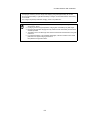
CAUTION
•Do not connect or disconnect equipment with wet hands, you are at risk of electric shocks if you
do!
•Risk of injury by overturn the carrying case.
Do not stand or sit on the carrying cases.
•Please note that the tips of tripod can be hazardous, be aware of this when setting up or carrying the tripod.
•Risk of injury by falling down the instrument or case.
Do not use a carrying case with a damaged which belts, grips or latches .
•Do not allow skin or clothing to come into contact with acid from the batteries, if this does occur
then wash off with copious amounts of water and seek medical advice.
•A plumb bob can cause an injury to a person if used incorrectly.
•It could be dangerous if the instrument falls over, please ensure you attach a handle to the instrument securely.
•Ensure that you mount the tribrach correctly, failing to do so may result in injury if the tribrach
were to fall over.
•It could be dangerous if the instrument falls over, please check that you fix the instrument to
the tripod correctly.
•Risk of injury by falling down a tripod and an instrument.
Always check that the screws of tripod are tightened.
4
FOREWORD
User
1)This product is for professional use only!
The user is required to be a qualified surveyor or have a good knowledge of surveying, in order to
understand the user and safety instructions, before operating, inspecting or adjusting.
2)Wear the required protectors (safety shoes, helmet, etc.) when operating.
Exceptions from Responsibility
1)The user of this product is expected to follow all operating instructions and make periodic checks of the
product’s performance.
2)The manufacturer, or its representatives, assumes no responsibility for results of a faulty or intentional
usage or misuse including any direct, indirect, consequential damage, and loss of profits.
3)The manufacturer, or its representatives, assumes no responsibility for consequential damage, and
loss of profits by any disaster, (an earthquake, storms, floods etc.).
A fire, accident, or an act of a third party and/or a usage any other usual conditions.
4)The manufacturer, or its representatives, assumes no responsibility for any damage, and loss of profits
due to a change of data, loss of data, an interruption of business etc., caused by using the product or
an unusable product.
5)The manufacturer, or its representatives, assumes no responsibility for any damage, and loss of profits
caused by usage except for explained in the user manual.
6)The manufacturer, or its representatives, assumes no responsibility for damage caused by wrong
movement, or action due to connecting with other products.
5
FOREWORD
Safety Standard for Laser Beam of Laser Plummet
GTS-720 series Laser plummet type use a visible laser beam to perform the plumb laser function. The
GTS-720 series Laser plummet type products are manufactured and sold in accordance with
"Radiation Safety of Laser Products, Equipment Classification, Requirements and User`s Guide" (IEC
Publication 825) or "Performance Standards for Light-Emitting Products" (FDA/BRH 21 CFR 1040)
regarding the safety standard for laser products.
As per these standards, the GTS-720 series Laser plummet type is classified as "Class II (2) Laser
Products".
Since Laser radiation is emitted from the GTS-720 series Laser plummet type instruments, please refer
to the "Laser Safety" bulletin which accompanies the instrument in the United States as well as the
"Safety Standard for Users" that is mentioned in the instruction manual.
In the case of any technical failure, do not disassemble the instrument. Contact either TOPCON or your
authorized TOPCON dealer.
Labels
The following labels are found on the instruments which describe the GTS-720 series Laser plummet
type:Precautions and safety information about the laser beam.
If, at any time, any of these labels are damaged and become illegible, please replace these important
labels. Please the new labels in exactly the same position as the original labels.
Replacement labels can be obtained from Topcon or your authorized Topcon dealer.
GTS-720 series Laser
Plummet type
Warning Label
Explanatory Label
CAUTION
LASER RADIATION-DO NOT
STARE INTO BEAM
WAVE LENGTH 633nm
1mW MAXIMUM OUTPUT
CLASS II LASER PRODUCT
Aperture Label
LASER RADIATION
AVOID EXPOSURE
DO NOT STARE INTO BEAM
LASER LIGHT IS EMITTED
FROM THIS APERTURE
Maximum output 1mW
CLASS 2
Wave length 633nm
LASER PRODUCT
Beam aperture
Depending on the country where the instrument is sold, either of these labels may be
found on the GTS-720 series laser plummet type.
Symbol Mark while the Laser is Emitting.
The following symbol mark will appear at the right side of the second line.
The symbol mark will come on while the laser
plummet is working
6
FOREWORD
Contents
FOREWORD. . . . . . . . . . . . . . . . . . . . . . . . . . . . . . . . . . . . . . . . . . . . . . . . . . . 1
General Handling Precautions . . . . . . . . . . . . . . . . . . . . . . . . . . . . . . . . . . . . . . . . . . . . . . . 2
Display for Safe Use . . . . . . . . . . . . . . . . . . . . . . . . . . . . . . . . . . . . . . . . . . . . . . . . . . . . . . . . 3
Safety Cautions . . . . . . . . . . . . . . . . . . . . . . . . . . . . . . . . . . . . . . . . . . . . . . . . . . . . . . . . . . . . 3
User. . . . . . . . . . . . . . . . . . . . . . . . . . . . . . . . . . . . . . . . . . . . . . . . . . . . . . . . . . . . . . . . . . . . . 5
Exceptions from Responsibility . . . . . . . . . . . . . . . . . . . . . . . . . . . . . . . . . . . . . . . . . . . . . . . . 5
Safety Standard for Laser Beam of Laser Plummet . . . . . . . . . . . . . . . . . . . . . . . . . . . . . . . . 6
Symbol Mark while the Laser is Emitting. . . . . . . . . . . . . . . . . . . . . . . . . . . . . . . . . . . . . . . . . 6
Contents . . . . . . . . . . . . . . . . . . . . . . . . . . . . . . . . . . . . . . . . . . . . . . . . . . . . . . . . . . . . . . . . . 7
Standard Set Composition . . . . . . . . . . . . . . . . . . . . . . . . . . . . . . . . . . . . . . . . . . . . . . . . . . . 9
1 NOMENCLATURE AND FUNCTIONS. . . . . . . . . . . . . . . . . . . . . . . . . . . 1-1
1.1 Nomenclature. . . . . . . . . . . . . . . . . . . . . . . . . . . . . . . . . . . . . . . . . . . . . . . . . . . . . . . . 1-1
1.2 Display . . . . . . . . . . . . . . . . . . . . . . . . . . . . . . . . . . . . . . . . . . . . . . . . . . . . . . . . . . . . . 1-3
1.2.1 Main Menu Contains . . . . . . . . . . . . . . . . . . . . . . . . . . . . . . . . . . . . . . . . . . . . . . 1-3
1.2.2 Measurement Menu . . . . . . . . . . . . . . . . . . . . . . . . . . . . . . . . . . . . . . . . . . . . . . 1-4
1.2.3 Display Marks . . . . . . . . . . . . . . . . . . . . . . . . . . . . . . . . . . . . . . . . . . . . . . . . . . . 1-4
1.2.4 Display keys . . . . . . . . . . . . . . . . . . . . . . . . . . . . . . . . . . . . . . . . . . . . . . . . . . . . 1-4
1.2.5 Shortcut Keys . . . . . . . . . . . . . . . . . . . . . . . . . . . . . . . . . . . . . . . . . . . . . . . . . . . 1-5
1.3 Backlight Adjustment . . . . . . . . . . . . . . . . . . . . . . . . . . . . . . . . . . . . . . . . . . . . . . . . . . 1-6
1.3.1 How to Adjust Reducing Time of Backlight . . . . . . . . . . . . . . . . . . . . . . . . . . . . 1-6
1.3.2 Adjust the Backlight Brightness by Manual . . . . . . . . . . . . . . . . . . . . . . . . . . . . . 1-8
1.3.3 Selecting the Automatic Lighting Option . . . . . . . . . . . . . . . . . . . . . . . . . . . . . . . 1-9
1.4 RAM Data Backup . . . . . . . . . . . . . . . . . . . . . . . . . . . . . . . . . . . . . . . . . . . . . . . . . . . 1-10
1.4.1 Execute the Backup Function . . . . . . . . . . . . . . . . . . . . . . . . . . . . . . . . . . . . . . 1-10
1.4.2 Set the Automatic Backup for Every Suspension . . . . . . . . . . . . . . . . . . . . . . . 1-12
1.4.3 Set the Restoration Disabled after Hardware Reset . . . . . . . . . . . . . . . . . . . . . 1-12
1.5 Hardware Reset . . . . . . . . . . . . . . . . . . . . . . . . . . . . . . . . . . . . . . . . . . . . . . . . . . . . . 1-13
1.6 Cover Sensor . . . . . . . . . . . . . . . . . . . . . . . . . . . . . . . . . . . . . . . . . . . . . . . . . . . . . . . 1-13
1.7 Touch Panel Calibration. . . . . . . . . . . . . . . . . . . . . . . . . . . . . . . . . . . . . . . . . . . . . . . 1-14
1.8 Operating Panel Key . . . . . . . . . . . . . . . . . . . . . . . . . . . . . . . . . . . . . . . . . . . . . . . . . 1-16
1.8.1 Operating Key . . . . . . . . . . . . . . . . . . . . . . . . . . . . . . . . . . . . . . . . . . . . . . . . . . 1-16
1.9 Power OFF. . . . . . . . . . . . . . . . . . . . . . . . . . . . . . . . . . . . . . . . . . . . . . . . . . . . . . . . . 1-17
1.10 Function Key (Soft Key) . . . . . . . . . . . . . . . . . . . . . . . . . . . . . . . . . . . . . . . . . . . . . . 1-18
1.11 Star Key Mode . . . . . . . . . . . . . . . . . . . . . . . . . . . . . . . . . . . . . . . . . . . . . . . . . . . . . 1-20
1.11.1 Setting by Using Star Key . . . . . . . . . . . . . . . . . . . . . . . . . . . . . . . . . . . . . . . . 1-22
1.12 Auto Power Off. . . . . . . . . . . . . . . . . . . . . . . . . . . . . . . . . . . . . . . . . . . . . . . . . . . . . 1-23
2 PREPARATION FOR MEASUREMENT . . . . . . . . . . . . . . . . . . . . . . . . . 2-1
2.1
2.2
2.3
2.4
2.5
Power Connection . . . . . . . . . . . . . . . . . . . . . . . . . . . . . . . . . . . . . . . . . . . . . . . . . . . . 2-1
Setting Instrument Up For Measurement. . . . . . . . . . . . . . . . . . . . . . . . . . . . . . . . . . . 2-2
Power Switch Key ON . . . . . . . . . . . . . . . . . . . . . . . . . . . . . . . . . . . . . . . . . . . . . . . . . 2-3
Battery Power Remaining Display . . . . . . . . . . . . . . . . . . . . . . . . . . . . . . . . . . . . . . . . 2-4
Vertical and Horizontal Angle Tilt Correction . . . . . . . . . . . . . . . . . . . . . . . . . . . . . . . . 2-5
2.5.1 Setting Tilt Correction by Soft Key . . . . . . . . . . . . . . . . . . . . . . . . . . . . . . . . . . . 2-6
2.6 Compensation of Systematic Error of Instrument . . . . . . . . . . . . . . . . . . . . . . . . . . . . 2-7
2.7 How to Enter Numerals and Alphabet Letters . . . . . . . . . . . . . . . . . . . . . . . . . . . . . . . 2-8
2.8 Data Memory Card. . . . . . . . . . . . . . . . . . . . . . . . . . . . . . . . . . . . . . . . . . . . . . . . . . . 2-12
2.9 Active Sync . . . . . . . . . . . . . . . . . . . . . . . . . . . . . . . . . . . . . . . . . . . . . . . . . . . . . . . . 2-13
2.9.1 Getting Connected . . . . . . . . . . . . . . . . . . . . . . . . . . . . . . . . . . . . . . . . . . . . . . 2-13
3 STANDARD MEASUREMENT MODE. . . . . . . . . . . . . . . . . . . . . . . . . . . 3-1
3.1 Angle Measurement . . . . . . . . . . . . . . . . . . . . . . . . . . . . . . . . . . . . . . . . . . . . . . . . . . .
3.1.1 Measuring Horizontal Angle Right and Vertical Angle. . . . . . . . . . . . . . . . . . . . .
3.1.2 Switching Horizontal Angle Right/Left . . . . . . . . . . . . . . . . . . . . . . . . . . . . . . . . .
3.1.3 Measuring from the Required Horizontal Angle . . . . . . . . . . . . . . . . . . . . . . . . .
3.1.4 Vertical Angle Percent Grade(%) Mode . . . . . . . . . . . . . . . . . . . . . . . . . . . . . . .
3.2 Distance Measurement . . . . . . . . . . . . . . . . . . . . . . . . . . . . . . . . . . . . . . . . . . . . . . . .
3.2.1 Setting of the Atmospheric Correction. . . . . . . . . . . . . . . . . . . . . . . . . . . . . . . . .
3.2.2 Setting of the Correction for Prism Constant. . . . . . . . . . . . . . . . . . . . . . . . . . . .
3.2.3 Distance Measurement (Continuous Measurement). . . . . . . . . . . . . . . . . . . . . .
3.2.4 Distance Measurement (Single/N-times Measurement) . . . . . . . . . . . . . . . . . . .
3.2.5 Fine/ Tracking / Coarse Measuring Mode . . . . . . . . . . . . . . . . . . . . . . . . . . . . . .
7
3-1
3-1
3-2
3-3
3-4
3-5
3-5
3-5
3-5
3-6
3-7
FOREWORD
3.2.6 Stake Out (S.O). . . . . . . . . . . . . . . . . . . . . . . . . . . . . . . . . . . . . . . . . . . . . . . . . . 3-8
3.3 Coordinate Measurement. . . . . . . . . . . . . . . . . . . . . . . . . . . . . . . . . . . . . . . . . . . . . . . 3-9
3.3.1 Setting Coordinate Values of Occupied Point . . . . . . . . . . . . . . . . . . . . . . . . . . . 3-9
3.3.2 Setting of the Instrument Height / Reflector(Prism) Height . . . . . . . . . . . . . . . . 3-11
3.3.3 Execution of Coordinate Measuring . . . . . . . . . . . . . . . . . . . . . . . . . . . . . . . . . 3-12
3.4 Data Output . . . . . . . . . . . . . . . . . . . . . . . . . . . . . . . . . . . . . . . . . . . . . . . . . . . . . . . . 3-13
3.5 Data Output by [REC] Key . . . . . . . . . . . . . . . . . . . . . . . . . . . . . . . . . . . . . . . . . . . . . 3-14
4 PARAMETERS SETTING MODE . . . . . . . . . . . . . . . . . . . . . . . . . . . . . . 4-1
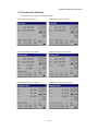
4.1 Parameter Setting Options. . . . . . . . . . . . . . . . . . . . . . . . . . . . . . . . . . . . . . . . . . . . . .
4.1.1 Measurement . . . . . . . . . . . . . . . . . . . . . . . . . . . . . . . . . . . . . . . . . . . . . . . . . . .
4.1.2 Communication . . . . . . . . . . . . . . . . . . . . . . . . . . . . . . . . . . . . . . . . . . . . . . . . . .
4.1.3 Value Input . . . . . . . . . . . . . . . . . . . . . . . . . . . . . . . . . . . . . . . . . . . . . . . . . . . . .
4.1.4 Unit . . . . . . . . . . . . . . . . . . . . . . . . . . . . . . . . . . . . . . . . . . . . . . . . . . . . . . . . . . .
4.2 Setting Parameters . . . . . . . . . . . . . . . . . . . . . . . . . . . . . . . . . . . . . . . . . . . . . . . . . . .
4-1
4-1
4-2
4-2
4-2
4-3
5 CHECK AND ADJUSTMENT. . . . . . . . . . . . . . . . . . . . . . . . . . . . . . . . . . 5-1
5.1 Checking and Adjusting of Instrument Constant . . . . . . . . . . . . . . . . . . . . . . . . . . . . . 5-1
5.2 Checking the Optical Axis . . . . . . . . . . . . . . . . . . . . . . . . . . . . . . . . . . . . . . . . . . . . . . 5-2
5.3 Checking/Adjusting the Theodolite Functions . . . . . . . . . . . . . . . . . . . . . . . . . . . . . . . 5-3
5.3.1 Checking /Adjusting the Plate Level . . . . . . . . . . . . . . . . . . . . . . . . . . . . . . . . . . 5-4
5.3.2 Checking /Adjusting the Circular Level . . . . . . . . . . . . . . . . . . . . . . . . . . . . . . . . 5-4
5.3.3 Adjustment of the Vertical Cross-hair . . . . . . . . . . . . . . . . . . . . . . . . . . . . . . . . . 5-5
5.3.4 Collimation of the Instrument. . . . . . . . . . . . . . . . . . . . . . . . . . . . . . . . . . . . . . . . 5-6
5.3.5 Checking / Adjusting the Optical Plummet Telescope. . . . . . . . . . . . . . . . . . . . . 5-7
5.3.6 Adjustment of Vertical Angle 0 Datum. . . . . . . . . . . . . . . . . . . . . . . . . . . . . . . . . 5-8
5.4 How to Set the Instrument Constant Value . . . . . . . . . . . . . . . . . . . . . . . . . . . . . . . . . 5-9
5.5 Compensation Systematic Error of Instrument . . . . . . . . . . . . . . . . . . . . . . . . . . . . . 5-10
5.5.1 Adjustment of Compensation Systematic Error of Instrument. . . . . . . . . . . . . . 5-10
5.5.2 Showing Compensation Systematic Error of Instrument. . . . . . . . . . . . . . . . . . 5-12
5.6 Reference Frequency Check Mode . . . . . . . . . . . . . . . . . . . . . . . . . . . . . . . . . . . . . . 5-13
6 SETTING ATMOSPHERIC CORRECTION. . . . . . . . . . . . . . . . . . . . . . . 6-1
6.1 Calculation of Atmospheric Correction. . . . . . . . . . . . . . . . . . . . . . . . . . . . . . . . . . . . . 6-1
6.2 Setting of Atmospheric Correction Value . . . . . . . . . . . . . . . . . . . . . . . . . . . . . . . . . . . 6-2
7 CORRECTION FOR REFRACTION AND EARTH CURVATURE. . . . . . 7-1
7.1 Distance Calculation Formula . . . . . . . . . . . . . . . . . . . . . . . . . . . . . . . . . . . . . . . . . . . 7-1
8 POWER SOURCE AND CHARGING. . . . . . . . . . . . . . . . . . . . . . . . . . . . 8-1
8.1 On-board Battery BT-61Q . . . . . . . . . . . . . . . . . . . . . . . . . . . . . . . . . . . . . . . . . . . . . . 8-1
9 DETACH/ATTACH OF TRIBRACH . . . . . . . . . . . . . . . . . . . . . . . . . . . .
10 SPECIAL ACCESSORIES . . . . . . . . . . . . . . . . . . . . . . . . . . . . . . . . . .
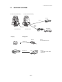
11 BATTERY SYSTEM . . . . . . . . . . . . . . . . . . . . . . . . . . . . . . . . . . . . . . .
12 PRISM SYSTEM. . . . . . . . . . . . . . . . . . . . . . . . . . . . . . . . . . . . . . . . . .
13 PRECAUTIONS . . . . . . . . . . . . . . . . . . . . . . . . . . . . . . . . . . . . . . . . . .
14 ERROR DISPLAYS . . . . . . . . . . . . . . . . . . . . . . . . . . . . . . . . . . . . . . .
. 9-1
10-1
11-1
12-1
13-1
14-1
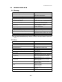
14.1 Message. . . . . . . . . . . . . . . . . . . . . . . . . . . . . . . . . . . . . . . . . . . . . . . . . . . . . . . . . . 14-1
14.2 Error . . . . . . . . . . . . . . . . . . . . . . . . . . . . . . . . . . . . . . . . . . . . . . . . . . . . . . . . . . . . . 14-1
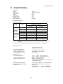
15 SPECIFICATIONS . . . . . . . . . . . . . . . . . . . . . . . . . . . . . . . . . . . . . . . . 15-1
APPENDIX . . . . . . . . . . . . . . . . . . . . . . . . . . . . . . . . . . . . . . . . . . . Appendix-1
Dual Axis Compensation........................................................................................ Appendix-1
8
FOREWORD
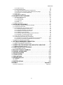
Standard Set Composition
The numerical value in parentheses shows the quantity.
GTS-720 series (with lens cap) (1)
Plastic carrying case(1)
Battery charger BC-30, AC-Cable (1)
Stylus penÅi2)
(1) (For GTS-725)
Sun shade(1)
Battery BT-61Q(1)
Plumb bob set(1)
Tool kit with case (1)
[ rod pin(2), screwdriver, hexagonal wrench(2),
cleaning brush ]
Plumb bob hanger is including
in the tool kit case.
Silicon cloth(1)
Plastic rain cover(1)
USB Cable F-25(1)
Display protect sheet(10)
Instruction manual (Standard Measurement) (1)
(Program)(1)
Instruction manual (TopSURV) (1)
CD-ROM (1)
Shoulder belt (2)
(Make sure that all of the above items are with the instrument when purchased.)
9
1 NOMENCLATURE AND FUNCTIONS
1
NOMENCLATURE AND FUNCTIONS
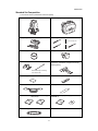
1.1 Nomenclature
Carrying handle
Sighting collimator
Handle fixing screw
Point guide
Objective lens
Instrument
center mark
Optical plummet
telescope
Display window
(With touch panel)
GTS-721/722/723
Power supply
connector
Operation keys
GTS-721/722/723
Communication port
(Serial signal connector RS-232C)
Stylus pen
Leveling screw
Base
GTS-721/722/723
1-1
1 NOMENCLATURE AND FUNCTIONS
Vertical tangent screw *1)
2speed way:
GTS-721/722/723
1speed way:
GTS-725
Power switch
Telescope focusing knob
Vertical motion clamp
Instrument
center mark
Telescope grip
Card cover
Hardware reset switch
Telescope eyepiece
(Inside the cover)
Card cover lever
Horizontal
tangent screw
2speed way:
GTS-721/722/723
Plate level
1speed way:
GTS-725
Display window
(With touch panel)
Horizontal
motion clamp
Operation keys
Circular level
Battery cover lever
Adjusting screw
for circular level
Battery cover
Cover sensor
USB port
Tribrach fixing lever
(Inside the cover)
Stylus pen
*1) The position of vertical motion clamp and tangent screw will differ depend on the markets.
1-2
1 NOMENCLATURE AND FUNCTIONS
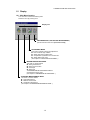
1.2 Display
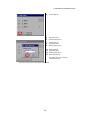
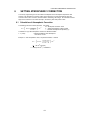
1.2.1 Main Menu Contains
The main menu contains as following items.
Select the menu by pressing icons.
Display icon
PROGRAM MODE ( APPLICATION MEASUREMENT)
(See the instruction manual of [PROGRAM MODE])
ADJUSTMENT MODE
This mode is used for checking and adjustment.
● Error of vertical angle 0 datum
● Setting instrument constant value
● Compensation systematic error of Instrument
● Setting FRQ check mode
(see Chapter 5 “CHECK AND ADJUSTMENT” .)
PARAMETERS SETTING MODE
This mode is used for follows
● Setting measurement
● Setting communication
● Value input
● Setting unit
The PARAMETERS SETTING MODE settled is
memorized even power is off.
(see Chapter 4 “PARAMETERS SETTING MODE” .)
STANDARD MEASUREMENT MODE
This mode is used for follows
● Angle measurement
● Distance measurement
● Coordinate measurement
(see Chapter 3 “STANDARD MEASUREMENT MODE” .)
1-3
1 NOMENCLATURE AND FUNCTIONS
1.2.2 Measurement Menu
Example:Distance Mode
V-angle: 90°30’35”
H-angle:120°00’00”
Horizontal distance: 0.150m
Relative elevation : -0.001m
Soft keys
1.2.3 Display Marks
Display
Contents
Display
Contents
V
V-angle
m
Meter unit
V%
Percent grade
ft
Feet unit
HR
H-angle right
F
Fine mode
HL
H-angle left
C
Coarse mode
HD
Horizontal distance
T
Tracking mode
VD
Relative elevation
R
Repeat measurement
SD
Slope distance
S
Single measurement
N
N coordinate
N
N-times measurement
E
E coordinate
PPM
Atmospheric correction value
Z
Z coordinate
PSM
Prism constant value
✻
EDM working
1.2.4 Display keys
Keys
Name of Key
Function
F1~F4
Soft key
ESC
Escape key
ANG
Angle
measuring key
To be angle measuring mode.
Distance
measuring key
To be distance measuring mode.
Coordinate
measuring key
To be coordinate measuring mode.
REC
REC key
Functions are according to the displayed message.
Returning to the previous mode or display.
Result of measurement is transferred.
1-4
1 NOMENCLATURE AND FUNCTIONS
1.2.5 Shortcut Keys
Software Reset
[Shift]+[Func]+[ESC]
Windows Start Menu
[Ctrl]+[ESC]
Shortcut Commands
Continue tapping on an item
or
[Alt]+Tap on an item
Windows CE
Task Manager
[Alt]+[TAB]
to switch to another active program or to END Task on running program(s).
1-5
1 NOMENCLATURE AND FUNCTIONS
1.3 Backlight Adjustment
To conserve battery power, this instrument would automatically turn the backlight off or reduce the
backlight brightness by itself when it’s not in use.
In addition, the instrument can control the backlight brightness automatically by an equipped
illuminometer.
You can adjust the settings of this function to conserve more battery power or set your liking.
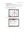
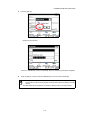
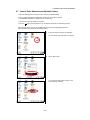
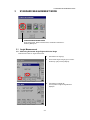
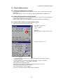
1.3.1 How to Adjust Reducing Time of Backlight
1
Press the icon [Start]-[Settings]-[Control Panel]-[Power].
You can see the "Power Properties" screen on Display.
2
Press the tab [Backlight].
You can see the "Backlight" screen on Display.
1-6
1 NOMENCLATURE AND FUNCTIONS
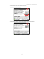
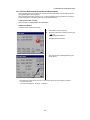
3
Press the time-menu down arrow to select the reducing time.
Factory setting is ‘3 minutes' as default.
4
Press the [OK] key on title bar. After that "Power Properties" screen will close automatically.
1-7
1 NOMENCLATURE AND FUNCTIONS
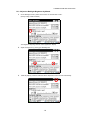
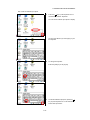
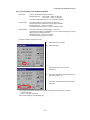
1.3.2 Adjust the Backlight Brightness by Manual
1
On the "Backlight" screen, please check it 'OFF' "An illuminometer is used.”.
(Factory setting is 'ON' as default)
The "Brightness adjusting slide bar” will be appeared on Display.
2
Adjust the brightness by pressing [UP-DOWN] button.
3
Press the [OK] key on title bar. After that "Power Properties" screen will close automatically.
1-8
1 NOMENCLATURE AND FUNCTIONS
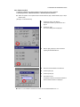
1.3.3 Selecting the Automatic Lighting Option
1
On the "Backlight" screen, select a Radio button from “Automatic lighting” column.
(Factory setting is “The light is switched on with an illuminometer.” as default)
2
Press the [OK] key on title bar. After that "Power Properties" screen will close automatically.
The “Time until it switches off a backlight.” time-menu is not activate if “The light is
switched on with an illuminometer.” option is selected.
1-9
1 NOMENCLATURE AND FUNCTIONS
1.4 RAM Data Backup
If your device had not recharged during several days, the battery will be running down, and you would
lose all of data on the device other than that in the "Internal Disk (internal SD card)".
In addition, you might perform hardwarereset by the hardware problem or software problem. In this
case, you would lose all data same as the above.
You can use Backup function of the instrument in order to evade such kind of uneasiness.Your data will
be restored to latest condition* automatically when rebooting by using the Backup function.
The Backup function saves all data files of RAM (except for OS files), registry file and additionally
installed programs into named "Backup" folder in the "Internal Disk".
* Restoring former backup data may be incomplete if you upgrade OS version.
* The conditions that you executed the backup function last.
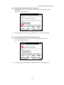
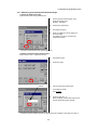
1.4.1 Execute the Backup Function
Make sure the mode is Windows CE mode.
1
Press the icon [Start]-[Settings]-[Control Panel]-[Backup].
You can see the "RAM Backup" screen on Display.
2
Press the [RAM data backup] key.
You can see the "Confirmation screen" on display.
1-10
1 NOMENCLATURE AND FUNCTIONS
3
Press the [YES] key.
Backup function will start.
Return to "RAM Backup" screen automatically, when the data back up has been completed.
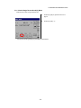
4
Press the [OK] key on title bar. After that "RAM Backup" screen will close automatically.
● Backing up data may be incomplete if remaining capacity of "Internal Disk" is not enough.
Please make sure the remaining capacity of "Internal Disk" before proceeding to the data
back up.
● Restoration will be impossible if you delete the "Backup" folder in the "Internal Disk".
1-11
1 NOMENCLATURE AND FUNCTIONS
1.4.2 Set the Automatic Backup for Every Suspension
1 On the "RAM Backup" Screen, please check it 'ON' the "RAM data will be backed up before
suspension.".
(Factory setting is 'ON' as default)
2
Press the [OK] key on title bar. After that, "RAM Backup" screen will close automatically.
1.4.3 Set the Restoration Disabled after Hardware Reset
1 On the "RAM Backup" Screen, check it 'OFF' the "Data restoration after hard reset.".
(Factory setting is 'ON' as default)
2
Press the [OK] key on title bar. After that, "RAM Backup" screen will close automatically.
1-12
1 NOMENCLATURE AND FUNCTIONS
1.5 Hardware Reset
If your instrument not responding or an application hangs, please try to perform a software reset first.
Still, when useless, please perform hardware reset.
You will lose all of data on the device other than that in the "Internal Disk" after hardware reset
and will need to reinstall the applications and the data you install on your instrument.
Card cover lever
Stylus pen
1
Pull the card cover lever to open the card cover.
2
Insert the stylus into the unit of hardware reset
switch.
3
Press the switch for two seconds.
The instrument will reboot.
Hardware reset switch
1.6 Cover Sensor
Completely close the battery cover before using the GTS-720.
Battery cover
Battery
Cover sensor
● If the battery cover is not completely closed, the GTS-720 will not operate normally,
regardless of whether the battery or the external power source is used.
● If the battery cover is opened while the GTS-720 is in operation, operation will
automatically be suspended.
1-13
1 NOMENCLATURE AND FUNCTIONS
1.7 Touch Panel Calibration
If your instrument is not responding properly to your taps, you may need to calibrate the touch panel.
● How to calibrate the touch panel
1
Press the icon [Start]-[Settings]-[Control Panel][Stylus].
You can see the "Stylus Properties" screen on
Display.
2
Press the tab “Calibration”.
3
Press the [Recalibrate] key.
1-14
1 NOMENCLATURE AND FUNCTIONS
4
Using the stylus pen, press the center of the
targets on the screen.
5
After pressing all targets (5 points), press the
[ENT] key.
6
Press the [OK] key.
The display returns to previous menu.
1-15
1 NOMENCLATURE AND FUNCTIONS
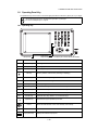
1.8 Operating Panel Key
To operate the keys on the screen, touch them lightly with either the accessory stylus pen or your finger.
To operate the touch panel, use either the stylus pen or your finger.
Do not use a ballpoint pen or a pencil.
1.8.1 Operating Key
Microphone
Light sensor:
adjust backlight
Keys
Name of Key
0~9
Numeric key
Entering numerals.
A ~/
Alpha key
Entering Alphabets.
Esc
Escape key
The stylus pen is stored beside the display.
Function
Returning to the previous mode or display.
Star key
Star key mode is used for each presetting or displaying.
ENT
Enter key
Press at the end of inputting values.
Tab
Tab key
B.S.
Back space key
Shift
Shift key
Used with other keys. Refer to "1.2.5 Shortcut Keys".
Ctrl
Control key
Used with other keys. Refer to "1.2.5 Shortcut Keys".
Alt
Alt key
Used with other keys. Refer to "1.2.5 Shortcut Keys".
Func
Function key
Used with other keys. Refer to "1.2.5 Shortcut Keys".
¿
Alphabet key
Switches the keys to alphabet input mode.
Cursor
S.P.
Space key
Input panel key
Moves the cursor to the right or downwards.
When inputting numbers or characters, return the cursor to the left.
Moves the selected item or the cursor laterally and vertically.
Inputs a space.
Displays the software input panel.
1-16
1 NOMENCLATURE AND FUNCTIONS
1.9 Power OFF
When turning off the power, be sure to turn off the GTS-720‘s power switch.
● Do not turn off the power by removing the battery.
Before removing the battery, press the power switch and confirm that the power is off.
Then remove the battery.
● While using the external power source, do not turn off the GTS-720 with the switch on the
external power source.
If the above-mentioned operating procedure is not followed, then, the next time that power
is turned on, it will be necessary to reboot the GTS-720.
1-17
1 NOMENCLATURE AND FUNCTIONS
1.10 Function Key (Soft Key)
The functions are according to the displayed message.
Angle measuring mode (Page 1)
Distance measuring mode (Page 1)
Coordinate measuring mode (Page 1)
Angle measuring mode (Page 2)
Distance measuring mode (Page 2)
Coordinate measuring mode (Page 2)
1-18
1 NOMENCLATURE AND FUNCTIONS
Angle measuring mode
Page
Soft
key
Display
F1
0SET
Angle of horizontal is set to 0° 00'00".
F2
HOLD
Holds the horizontal angle.
F3
HSET
Sets the horizontal angle by input value.
F4
P1
F1
TILT
Sets the tilt function, ON/OFF.
If ON, the display shows tilt correction value.
F2
V/%
Switches the vertical angle and percent grade.
F3
R/L
Switches R/L rotation of horizontal angle.
F4
P2
The function of soft keys on next page (P1).
Function
1
2
The function of soft keys on next page (P2).
Distance measuring mode
F1
MEAS
Distance measuring starts.
F2
MODE
Sets to the mode for Tracking , Coarse or Fine.
F3
---
---
F4
P1
The function of soft keys on next page (P2).
F1
S.O
To be stake out measurement mode.
F2
---
---
F3
---
---
F4
P2
The function of soft keys on next page (P1).
1
2
Coordinate measuring mode
F1
MEAS
Coordinate measuring starts.
F2
MODE
Sets to the mode for Tracking , Coarse or Fine.
F3
---
---
F4
P1
The function of soft keys on next page (P2).
F1
R.HT
F2
INSHT
F3
OCC
F4
P2
1
Sets a Reflector Height by input value.
Sets an Instrument Height by input value.
2
Sets an occupied point by input values.
The function of soft keys on next page (P1).
1-19
1 NOMENCLATURE AND FUNCTIONS
1.11 Star Key Mode
Press the star(
) key to view the instrument options.
The following instrument options can be selected from the star key:
Reticle illumination icon
Point guide icon
Set audio icon
Laser plummet icon
(Only for Laser Plummet type)
Prism constant value,
Atmospheric correction icon
Electric circular level icon
● Electric circular level graphic display
Electric circular level can be displayed by graphic. This function is good for level the instrument
when the circular level is difficult to see directly.
In the displays of reverse side, the graphic bubble moves in reverse.
Rotate the leveling screws while observing the display.
1-20
1 NOMENCLATURE AND FUNCTIONS
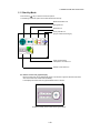
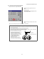
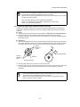
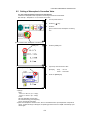
● Point guide ON/OFF
This feature is most useful when doing stake out work. The Point Guide's red LEDs on the GTS-720
Series telescope assist the rod person in getting on-line. The Point Guide feature is fast and simple
to use.
The Point Guide should be used within a distance of
100 meters (328 ft.). The quality of its results will
depend on the weather conditions and the user's
eyesight.
The goal of the rod person is to look at both LEDs
on the instrument and move the prism on-line until
both LEDs become equally bright . If the solid LED
is brighter, move to the right. If the blinking LED is
brighter, move to the left.
Instrument
Illuminate
Blink
Prism
● Set audio mode (S/A mode)
The light acceptance quantity level (Signal level) is displayed in this mode.
When reflected light from the prism is received, a buzzer sounds. This function is good for easy
collimation when the target is difficult to find.
The received return signal level is displayed with bar graph as follows.
● Reticle illumination
Select the brightness by sliding [UP-DOWN] slider.
The brightness setting is stored in memory after power is turned off.
To turn on or off the reticle illumination, press the [reticle illumination] icon.
[OFF]
Reticle illumination icon
[UP-DOWN] slider
[ON]
Reticle illumination icon
[UP-DOWN] slider
1-21
1 NOMENCLATURE AND FUNCTIONS
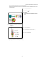
● Laser Plummet ( Only for Laser Plummet type)
Laser plummet option will help you to center the instrument easily onto the measurement point.
The following symbol mark will indicate that the laser is emitting.
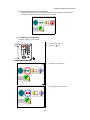
1.11.1 Setting by Using Star Key
[Example] : Switch on the point guide
1
2
Turn the power switch on.
3
Press the [Point Guide] icon.
Press the [
] key.
The point guide will be turned on.
1-22
1 NOMENCLATURE AND FUNCTIONS
1.12 Auto Power Off
To save battery power, the GTS-720 would automatically turn the power off (suspend) by itself
when it’s not in use. You can adjust the settings of this function.
●
How to adjust the settings of auto power off function
1
Press the icon [Start]-[Settings][Control Panel]-[Power].
You can see the "Power Properties" screen on
Display.
2
Press the tab “Power Off”.
3
Press the time-menu down arrow to select the
auto power off time.
(Factory setting is '10 minutes' as default)
1-23
1 NOMENCLATURE AND FUNCTIONS
4
Press the [OK] key on title bar.
After that "Power Properties" screen will close
automatically.
While on external power, the auto power off function can be enabled too.
To set this function, please check it 'ON' the "Enable suspend while on external power” on
the "Power Off " screen, and select the auto power off time.
(Factory setting is 'OFF' as default)
1-24
2 PREPARATION FOR MEASUREMENT
2
PREPARATION FOR MEASUREMENT
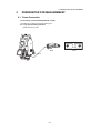
2.1 Power Connection
(unnecessary if on-board battery BT-61Q is used)
See below for connecting the external battery pack.
● Large capacity battery pack BT-3L
Power cord PC-6 is used.
BT-3L
PC-6
2-1
PC-6
2 PREPARATION FOR MEASUREMENT
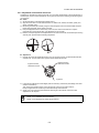
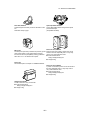
2.2 Setting Instrument Up For Measurement
Mount the instrument to the tripod. Level and center the instrument precisely to insure the best
performance. Use tripods with a tripod screw of 5/8 in. diameter and 11 threads per inch, such as the
Type E TOPCON wide- frame wooden tripod.
Reference: Leveling and Centering the Instrument
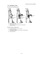
1. Setting up the Tripod
First, extend the extension legs to suitable lengths
and tighten the screws on their midsections.
2. Attaching the Instrument on the Tripod
Head
Place the instrument carefully on the tripod head
and slide the instrument by loosening the tripod
screw. If the plumb bob is positioned right over the
center of the point, slightly tighten the tripod
screw.
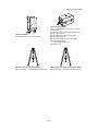
3. Roughly Leveling the Instrument by Using
the Circular Level
1 Turn the leveling screws A and B to move the
bubble in the circular level. The bubble is now
located on a line perpendicular to a line
running through the centers of the two leveling
screws being adjusted.
Leveling screw C
Leveling
screw A
2
Rotate the instrument 90° (100g) around its
vertical axis and turn the remaining leveling
screw or C to center the bubble once more.
Leveling screw C
90
3
Repeat the procedures 1 and 2 for each 90°
(100g) rotation of the instrument and check
whether the bubble is correctly centered for all
four points.
5. Centering by Using the Optical Plummet
Telescope
Adjust the eyepiece of the optical plummet
telescope to your eyesight.
Slide the instrument by loosening the tripod
screw, place the point on the center mark, and
then tighten the tripod screw. Sliding the
instrument carefully not to rotate that allows you
to get the least dislocation of the bubble.
Leveling screw B
Point
2
Turn the leveling screw C to bring the bubble
to the center of the circular level.
4. Centering by Using the Plate Level
1 Rotate the instrument horizontally by using
the Horizontal motion/clamp screw and place
the plate level parallel with the line connecting
leveling screws A and B, and then bring the
bubble to the center of the plate level by
turning leveling screws A and B.
Center mark
6. Completely Leveling the Instrument
Leveling the instrument precisely in a similar way
to 4. Rotate the instrument and check to see that
the bubble is in the center of the plate level
regardless of telescope direction, then tighten the
tripod screw hard.
Leveling
screw A
Leveling
screw B
2-2
2 PREPARATION FOR MEASUREMENT
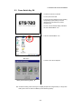
2.3 Power Switch Key ON
1
Confirm the instrument is leveled.
Turn the power switch ON.
Progress bar will be displayed during reloading
the Operating System, after you turn the
instrument on at the first time or perform
hardware reset.
You will see the Desktop display of Windows
CE with “Standard Meas.” icon.
2
Press the “Standard Meas.” icon.
Main menu
The main menu will be displayed.
Battery Power Remaining Display
● Confirm the battery power remaining on the display. Replace with charged battery or charge when
battery level is low. see section 2.4“Battery Power Remaining Display” .
2-3
2 PREPARATION FOR MEASUREMENT
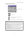
2.4 Battery Power Remaining Display
Battery power remaining display indicates the power condition.
Battery Power Remaining Display
Measurement is possible.
The power is poor. The battery should be recharged or replaced
with a fully charged battery.
Measurement is impossible -- need to recharge or replaces the battery.
Note:
1) The battery operating time will vary depending on the environmental conditions such as
ambient temperature, charging time, the number of times of charging and discharging etc. It
is recommended for safety to charge the battery beforehand or to prepare spare full charged
batteries.
2) For general usage of the battery, see Chapter 8 “POWER SOURCE AND CHARGING” .
3) The battery power remaining display shows the power level regarding to the measurement
mode now operating.
The safety condition indicated by the battery power remaining display in the angle
measurement mode does not necessarily assure the battery‘s ability to be used in the
distance measurement mode.
It may happen that the mode change from the angle mode to the distance mode will stop the
operation because of insufficient battery power for the distance mode which consumes more
power than angle mode.
4) When the measurement mode is changed, it rarely may happen that the Battery Power
Remaining Display will decrease or increase two steps momentarily because of the
accuracy of the battery checking system is rough. It is not trouble with the instrument.
2-4
2 PREPARATION FOR MEASUREMENT
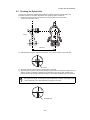
2.5 Vertical and Horizontal Angle Tilt Correction
When the tilt sensors are activated, automatic correction of vertical and horizontal angle for
mislevelment is displayed.
To ensure a precise angle measurement, tilt sensors must be turned on. The display can also be used
to fine level the instrument. If the (TILT OVER) display appears the instrument is out of automatic
compensation range and must be leveled manually.
Zenith
Standing axis
Zenith
Standing axis
Inclination of the standing
axis in the Y direction
Inclination of the standing
axis in the X direction
Trunnion axis
Horizontal
NT
2-FRO
● GTS-720 compensates both the vertical angle and the horizontal angle readings due to inclination
of the standing axis in the X and Y directions .
● For more information about dual axis compensation, see Chapter “APPENDIX” .
When the instrument is out of compensation. (TILT OVER)
Standing Axis in the X direction
out of range
Standing Axis in the Y direction
out of range
Standing Axis in the X and Y
directions out of range
● The display of Vertical or Horizontal angle is unstable when instrument is on an unstable stage or a
windy day. You can turn off the auto tilt correction function of V/H angle in this case.To set TILT
correction mode ON/OFF, refer to section 2.5.1 “Setting Tilt Correction by Soft Key”or Chapter 4
“PARAMETERS SETTING MODE”
2-5
2 PREPARATION FOR MEASUREMENT
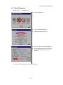
2.5.1 Setting Tilt Correction by Soft Key
[Example] Setting Tilt OFF
1
Press the [F4] key to get the function page 2.
2
Press the [F1] key.
Current setting is displayed.
3
Press [OFF] key.
4
Press [EXIT] key.
The display returns previous mode.
● The setting performed here will be interlocked with setting in Chapter 4 “PARAMETERS SETTING
MODE”
2-6
2 PREPARATION FOR MEASUREMENT
2.6 Compensation of Systematic Error of Instrument
1) Error of vertical axis (X,Y tilt sensor offset)
2) Collimation error
3) Error of vertical angle 0 datum
4) Error of horizontal axis
The above mentioned errors can be compensated by software, which calculated internally
according to each compensation value.
Also these errors can be compensated by software collimating one side of the telescope that is
carried out to delete the error by turning in normal and reverse both sides of telescope so far.
● To adjust or reset the above compensation value, see Chapter 5 “CHECK AND ADJUSTMENT” .
● Enable you to stop this function, see Chapter 4 “PARAMETERS SETTING MODE” or Chapter 5
“CHECK AND ADJUSTMENT”
2-7
2 PREPARATION FOR MEASUREMENT
2.7 How to Enter Numerals and Alphabet Letters
This instrument supports two ways to enter numerals and alphabet letters.
One is by physical(hardware) keyboard that is similar to cellular phone method.
Three alphabet characters are assigned to one numeral key.
The other is by using the software input panel.
Press the [
] key or press keyboard icon on the task bar will invoke the software input panel.
● [Example] : Enter “job_104” as the New Folder name by physical(hardware) keyboard.
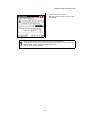
Make sure the mode is Windows CE desktop screen.
1
Press and hold the background of Desktop.
You can see the "Pull down menu" on Display.
2
Select “New Folder”.
You can see the "New Folder" waiting a new
name inputting on Display.
2-8
2 PREPARATION FOR MEASUREMENT
3
Press the [
letter mode.
¿ ] key to be entering alphabet
Alphabet letter mode indicator will be appeared
on the task bar.
Alphabet letter mode indicator
4
Enter Alphabets.
Input 'j',
Press [4](JKL)key. then the sub window
featuring 'j' character will appear on the display
which indicate a entering character.
Then ‘j’ will be displayed.
5
Input 'o',
Press [5](MNO),[5],[5].
The character in the sub window will be altered
'm', 'n', 'o'.
Then ‘o’ will be appended after ‘j’.
m
n
6
Input ‘b’,
Press [7](ABC), [7].The character in the sub
window will be altered 'a', 'b'.
Then ‘b’ will be appended after ‘jo’.
7
Input ‘_’,
Press [3](YZ_), [3], [3].
The character in the sub window will be altered
'y', 'z', ‘_’.
Then ‘_’ will be appended after ‘job’.
o
2-9
2 PREPARATION FOR MEASUREMENT
8
Press the [ ¿ ] key to be returning numeric
mode.
Alphabet letter mode indicator will be
disappeared on the task bar.
9
Input ‘104’,
Press [1], [0], [4].
Then ‘104’ will be appended after ‘job_’.
10 Press [ENT] key.
In alphabet letter mode, [Shift] + [0-9,.-] keys perform uppercase character.
2-10
2 PREPARATION FOR MEASUREMENT
● Invoke the software input panel.
1
Press the [ ] key or press keyboard icon on
the task bar and select “Keyboard”
You can see the software input panel on display.
You can input data as if you were typing on your
PC keyboard.
2
To change the keyboard:
Press the [CAP] key or the [au] key.
3
2-11
To hide the software input panel, press the [ ]
key or press keyboard icon on the task bar and
select “Hide Input Panel”.
2 PREPARATION FOR MEASUREMENT
2.8 Data Memory Card
● How to insert a memory card
Card cover
Card cover
lever
1
2
3
Card guide
Data memory
card
Pull the card cover lever to open the card cover.
Insert a memory card.
Make sure the card is inserted firmly in the correct direction.
Close the card cover.
● How to extract a memory card
1
2
3
4
Pull the card cover lever to open the card cover.
Pull down the card guide.
Note: Hold the card with your hand to protect the card against falling.
Extract the memory card.
Close the card cover.
2-12
Card guide
2 PREPARATION FOR MEASUREMENT
2.9 Active Sync
Microsoft ActiveSync is the data synchronization softwaresoftware: it synchronizes data between
Windows CE devices (such as the GTS-720) and PCs.
Using ActiveSync, the GTS-720 can exchange data to a PC via USB cable.
To establish a connection between the GTS-720 and your PC, you first need to install ActiveSync in
your PC.
For downloading ActiveSync, access the following website.
http://www.microsoft.com/windowsmobile/
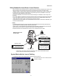
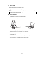
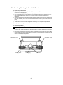
2.9.1 Getting Connected
1
Install ActiveSync in your PC (if it is not already installed).
2
Connect the GTS-720 to your PC with an interface cable F-25 as shown below.
GTS-720
PC
Interface(USB) cable F-25
USB Port (mini B)
USB Port (A)
3
The GTS-720 will give the prompt, “Conneting to Host”.
4
The PC will prompt you to set up a partnership or set up as a guest.
5
Select the [NO] key to setting up as a guest.
6
Press the [Next] key.
Once a connection has been established, the ActiveSync window will appear on your PC.
7
Click the [Explore] icon. You will then see the GTS-720 file structure.
2-13
3 STANDARD MEASUREMENT MODE
3
STANDARD MEASUREMENT MODE
STANDARD MEASUREMENT MODE
Angle measurement, Distance measurement, Coordinate measurement .
Press the [MEAS] icon.
3.1 Angle Measurement
3.1.1 Measuring Horizontal Angle Right and Vertical Angle
Make sure the mode is in angle measurement.
3-1
1
Collimate the 1st target (A).
2
Set horizontal angle of target (A) at 0° 00' 00".
Press the [F1] key and the [YES] key.
3
Collimate the 2nd target (B).
The required H/V angle to target B will be
displayed.
3 STANDARD MEASUREMENT MODE
3.1.2 Switching Horizontal Angle Right/Left
Make sure the mode is angle measurement.
1
Press the [F4] key to get the function as on
page 2.
2
Press the [F3] key.
The mode Horizontal angle Right(HR) switches
to angle Left(HL) mode.
3
Measure the target in the same manner as HR
mode.
● Every time pressing the [F3] key is pressed, HR/HL mode switches.
.
Reference : How to Collimate
1
2
3
Point the telescope toward the light.Turn the diopter ring and adjust the diopter so that the cross
hairs are clearly observed.
(Turn the diopter ring toward you first and then backward to focus.)
Aim the target at the peak of the triangle mark of the sighting collimator. Allow a certain space
between the sighting collimator and yourself for collimating.
Focus the target with the focusing knob.
*If parallax is created between the cross
hairs and the target when viewing
vertically or horizontally while looking
into the telescope, focusing is incorrect
or diopter adjustment is poor.
This adversely affects precision in
measurement or survey.
Eliminate the parallax by carefully
focusing and using diopter adjustment.
Focusing knob
Telescope eyepiece (Diopter ring)
Åá
Åá
3-2
Åá
Åá
3 STANDARD MEASUREMENT MODE
3.1.3 Measuring from the Required Horizontal Angle
1) Setting by Holding the Angle
Make sure the mode is angle measurement.
1
Set the required horizontal angle, using
Horizontal tangent screw.
Example : 120°00'00"
2
Press the [F2] (HOLD) key .
3
Collimate the target.*1)
4
Press the [YES] key to finish holding the
horizontal angle.
The display turns back to normal angle
measurement mode.
*1)To return to the previous mode, press the [NO] key.
2) Setting a Horizontal Angle from the Keys
Make sure the mode is angle measurement.
70.2030
1
Collimate the target.
2
Press the [F3] key .
3
Input the required horizontal angle.
For example:70°20'30"
Input 70.2030
4
Press the [SET] key. *1)
When completed, normal measuring from the
required Horizontal angle is possible.
*1)With wrong input value(for example 70'), setting will not be completed. Input again from step 3.
3-3
3 STANDARD MEASUREMENT MODE
3.1.4 Vertical Angle Percent Grade(%) Mode
Make sure the mode is angle measurement.
1
Press the [F4] key to get the function as on
page 2.
2
Press the [F2] key. *1)
*1) Every time pressing the [F2] key, the display mode switches.
3-4
3 STANDARD MEASUREMENT MODE
3.2 Distance Measurement
3.2.1 Setting of the Atmospheric Correction
When setting the atmospheric correction, obtain the correction value by measuring the temperature
and pressure.
Setting the atmospheric correction, see Chapter 6 “SETTING ATMOSPHERIC CORRECTION” .
3.2.2 Setting of the Correction for Prism Constant
Topcon's prism constant value is 0. Set correction for prism at 0. If the prism is of another manufacture,
the appropriate constant shall be set beforehand.
Setting the prism constant value, see Chapter 6 “SETTING ATMOSPHERIC CORRECTION” .
3.2.3 Distance Measurement (Continuous Measurement)
Make sure the mode displays angle measurement.
1
2
Collimate the center of prism.
Press the [
*1),*2)
] key.
[Example]:
Horizontal distance / Relative elevation mode
The result are shown.*3) ~ *7)
*1)ÅA*
*1)The following characters will be shown on the 4th line right hand of the display to represent
measurement mode.
F=Fine; C=Coarse; T=Tracking; R=Continuous (Repeat); S=Single; N=N-times
*2)When EDM is working, the " *" mark appears in the display.
*3)The result is shown with buzzer sound.
*4)Measurement may repeat automatically if the result is affected by shimmer etc..
*5)To change single measuring, press the [F1] key.
*6)To change SD/HD&VD, press the [
] key.
*7)To return to the angle measurement mode, press the [ANG] key.
3-5
3 STANDARD MEASUREMENT MODE
3.2.4 Distance Measurement (Single/N-times Measurement)
When presetting the number of times, the instrument measures the distance as the setting times and
the average distance will be displayed.
When presetting the number of times as 1 or 0, it does not display the average distance, because of
single measurement. It has been set at single measurement at factory.
1)Setting the number of times
Refer to Chapter 4 “PARAMETERS SETTING MODE” .
2)Measuring Method
Confirm the angle measurement mode.
1
2
Collimate the center of the prism.
Select the measurement mode by pressing the
[
] key.
Example:Horizontal distance
N-times measurement starts.
The average value is displayed following with
buzzer sound.
*1)
*1)The following characters will be shown on the 4th line right hand of the display to represent
measurement mode.
R=Continuous (Repeat); S=Single; N=N-times
3-6
3 STANDARD MEASUREMENT MODE
3.2.5 Fine/ Tracking / Coarse Measuring Mode
•Fine mode
: This is a normal distance measuring mode.
Measurement time
0.2mm mode : approx.2.8 seconds
1 mm mode : approx.1.2 seconds
The unit to be displayed is 0.2mm or 1mm. (0.001ft or 0.005ft)
•Coarse mode
: This mode measures in shorter time than in fine mode.
Use this mode for the objects which may be slightly unstable.
Measurement time : approx. 0.7seconds
The unit to be displayed is 1mm or 10mm. (0.005ft or 0.02ft)
•Tracking mode : This mode measures in shorter time than in fine mode.
Use this mode for stake out measurement. It is very useful when tailing the moving
object or carrying out stake-out work.
Measurement time : approx. 0.4 seconds
The unit to be displayed is 10mm. (0.02ft)
Confirm the distance measurement mode.
1
Collimate the center of prism.
2
Press the [F2] key.
The first letter of the current mode is
displayed.*1)
3
Select the measurement mode by pressing the
[F1], [F2] or [F3] key. *2)
The mode is set and distance measuring mode
reappears.
*1)The following characters will be shown on the 4th line right hand of the display to represent
measurement mode.
F=Fine; C=Coarse; T=Tracking
*2)To cancel the setting, press the [ESC] key.
3-7
3 STANDARD MEASUREMENT MODE
3.2.6 Stake Out (S.O)
The difference between the measured distance and the distance preset is displayed.
The displayed value = Measured distance - Standard (Preset) distance
● Stake out operation can be performed for horizontal distance (HD), relative elevation (VD) or slope
distance (SD)
[Example : Horizontal distance]
1
Press the [F4] key in the distance
measurement mode to get the function as in
page 2.
2
Press the [F1] key .
The current setting value is displayed.
3
With the [HD] - [SD] keys, select a mode for
inputting the standard distance.
4
Enter the horizontal distance for stake out.
5
Press the [SET] key.
6
Press the [EXIT] key.
7
Collimate the Prism.
The difference between the measured distance
and the standard distance is displayed.
●To return to normal distance measurement mode, reset the standard distance to “ 0 ”.
3-8
3 STANDARD MEASUREMENT MODE
3.3 Coordinate Measurement
3.3.1 Setting Coordinate Values of Occupied Point
Set the coordinates of instrument (occupied point) according to coordinate origin, and the instrument
automatically converts and displays the unknown point (reflector point) coordinates following the origin.
Reflector (n,e,z)
N
z
n
Inst.Point C
Origin(0,0,0)
E
e
Confirm the angle measurement mode.
3-9
1
Press the [
2
Press the [F4] key.
3
Press the [F3] key.
The previous data will be shown.
] key.
3 STANDARD MEASUREMENT MODE
4
Press the [N] key.
5
6
Input the N coord.
Press the [SET] key.*1)
7
8
9
Press the [E] key.
Input the E coord.
Press the [SET] key.*1)
10
11
12
13
Press the [Z] key.
Input the Z coord.
Press the [SET] key.*1)
Press the [EXIT] key.
The display returns to coordinate
measurement mode.
*1)To return to the previous mode, press the [EXIT] key.
3-10
3 STANDARD MEASUREMENT MODE
3.3.2 Setting of the Instrument Height / Reflector(Prism) Height
Measure the coordinates by entering the instrument height / reflector height, coordinates of unknown
point will be measured directly.
[Example] : Instrument height
Confirm the angle measurement mode.
1
Press the [
2
Press the [F4] key to get the function as in
page 2.
3
Press the [F2] key .
] key.
The previous data will be shown.
4
Press the [INPUT] key.
5
Input instrument height, and press [SET]
key.*1)
Press the [EXIT] key.
6
The display returns to coordinate
measurement mode.
*1)To return to the previous mode, press the [EXIT] key.
3-11
3 STANDARD MEASUREMENT MODE
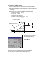
3.3.3 Execution of Coordinate Measuring
Measure the coordinates by entering the instrument height and reflector height, coordinates of
unknown point will be measured directly.
● When setting coordinate values of occupied point, see section 3.3.1“Setting Coordinate Values of
Occupied Point” .
● When setting the instrument height and reflector height, see section 3.3.2“Setting of the Instrument
Height / Reflector(Prism) Height” .
● The coordinates of the unknown point are calculated as shown below and displayed:
Coordinates of occupied point : (N0,E 0,Z0)
Instrument height : INST.HT
Reflector height
: R.HT
Vertical distance(Relative elevation) : z
Coordinates of the center of the reflector,
originated from the center point of the instrument : (n,e,z)
Coordinates of unknown point : (N1,E 1,Z1)
N1=N0+n
E1=E0+e
Z1=Z0+INST.HT+z - R.HT
Coordinates of the center of the reflector, originated from the center point of the instrument (n,e,z)
Center point of the instrument
(No, Eo, Zo+INST.HT)
Unknown point
(N 1, E1, Z1)
Occupied point (No, Eo, Zo)
Origin (o, o, o)
Confirm the angle measurement mode.
1
2
3
4
Set coordinates values of occupied point
and instrument/reflector height. *1)
Set the direction angle of known point A. *2)
Collimate the reflector.
Press the [
] key.
Measuring starts.
*1) In case the coordinate of occupied point is not entered, (0,0,0) will be used as the default for the
occupied point.
The instrument height will be calculated as 0 when the instrument height is not entered.
The reflector height will be calculated as 0 when the reflector height is not set.
*2) Refer to section 3.1.3“Measuring from the Required Horizontal Angle” .
3-12
3 STANDARD MEASUREMENT MODE
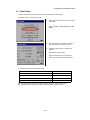
3.4 Data Output
Result of measurement is transferred from the GTS-720 series to Data Collector.
[Example: Distance measurement mode]
1
With the SETUP mode, set the communication
parameters.
Refer to Chapter 4 “PARAMETERS SETTING
MODE” .
2
After setting the communication parameters,
select the distance measurement mode.
3
Operate the data collector to measure the
distance.
Measurement will be started.
After the measurement, the result will be
shown and transferred to the Data Collector.
The following data will be output at each mode.
Mode
Output
Angle mode ( V,HR or HL) ( V in percent)
V, HR (or HL)
Horizontal distance mode (V,HR, HD, VD)
V, HR, HD, VD
Slope distance mode (V, HR,SD)
V, HR, SD,HD
Coordinate mode
N, E, Z, HR
● The display and the output at the coarse mode are the same as the contents above.
● Output at the tracking mode is displayed as distance data only (HD,VD or SD).
3-13
3 STANDARD MEASUREMENT MODE
3.5 Data Output by [REC] Key
It is also possible to output the result of measurement by pressing the [REC] key .
[Example: Distance measurement mode]
1
With the SETUP mode, set the communication
parameters.
Refer to Chapter 4 “PARAMETERS SETTING
MODE” .
2
After setting the communication parameters,
select the distance measurement mode.
3
Press the [REC] key.
Measurement will be started.
4
After the measurement, press the [Yes] key.
The data will be transferred to the Data
Collector.
3-14
4 PARAMETERS SETTING MODE
4
PARAMETERS SETTING MODE
PARAMETERS SETTING MODE
In this mode, setting of parameters regard with
measuring and communications will be done.
When a parameter is changed and set, the new
value is stored into the memory.
4.1 Parameter Setting Options
4.1.1 Measurement
Menu
Selecting Item
Contents
MINI ANG READING
NORM / MINI
Select the minimum display angle reading unit.
CRS READING
10mm / 1mm
Select 10mm/1mm for the minimum distance in coarse
mode.
FINE READING
1mm / 0.2mm
Select 1mm/0.2mm for the minimum distance in fine mode.
TILT
OFF/X-ON/XY-ON
Select the tilt sensor option for OFF, X-ON, XY-ON.
Select the error correction ON or OFF for collimation and
error adjustment.
3AXIS
CONPENSATION
POWER ON MODE
OFF/ON
ANGLE/DIST
Perform this item after complete Chapter 5.5 “ Compensation
Systematic Error of Instrument” .
For more information, refer to Chapter 5.3.6 “Adjustment of
Vertical Angle 0 Datum” and Chapter 5.5.2 “Showing
Compensation Systematic Error of Instrument” .
Select the measuring mode when the power is on to angle
measurement or distance measurement.
FINE/CRS/TRK
After turning on the power, select the same measuring mode
(FINE/CRS/TRK) as when distance measurement was
initially carried out.
HD&VD/SD
After turning on the power, select the same measuring mode
(HD&VD/SD) as when distance measurement was initially
carried out.
ZENITH/
HORIZONTAL
Select the vertical angle reading for Zenith 0 or Horizontal 0.
DIST MEAS
NUMBER
REPEAT/N TIME
After turning on the power, select the same measuring mode
(REPEAT/N TIME) as when distance measurement was
initially carried out.
NEZ / ENZ
NEZ / ENZ
DIST MODE
DIST DISPLAY
V ANGLE Z0/H0
W CORRECTION
OFF/0.14/0.20
Select the display format in the coordinate measurement
mode for NEZ or ENZ.
Select the coefficient correction for refraction and earth
curvature. Selections for the refraction coefficient are; OFF
(No correction), K=0.14 or K=0.20.
4-1
4 PARAMETERS SETTING MODE
REC TYPE
NEZ REC FORM
S/A BUZZER
REC-A/REC-B
Select the option to record the data.
REC-A : The measurement is started and new data is output.
REC-B : The data being displayed is output.
STANDARD/
WITH RAW
Select to record coordinates in standard or 11 digits with raw
data.
OFF/ON
Select the Audio tone OFF or ON for the Set Audio Mode.
4.1.2 Communication
Factory default settings are indicated with underlines.
Menu
BAUD RATE
Selecting Item
1200 / 2400 / 4800 /
9600/19200
DATA LENGTH
PARITY BIT
STOP BIT
7 BIT/ 8BIT
NON/EVEN/ODD
1 BIT/ 2BIT
Contents
Select the baud rate.
Select the data length seven digits or eight digits.
Select the parity bit.
Select the stop bit.
OFF/ON
Select the option OFF or ON for carriage return and line feed
when collecting measurement data with a computer.
OFF/ON
When communicating to an external device, the protocol for
handshaking can omit the [ACK] coming from the external
device so data is not sent again.
OFF : Omit the [ACK]
ON : Standard
Selecting Item
Contents
0~99
N-times measurement set.
Set N (number of times) for times of distance measurement.
When setting number of times as 1 or 0, it is single
measurement.
0~99
The time when EDM is cut off from distance measurement is
completed can be changed.
0
: After completing distance measurement,
EDM is cut off immediately.
1-98 : EDM is cut off after 1~98 minutes.
99
: EDM is always switched ON.
Selecting Item
Contents
TEMP
Celsius/Fahrenheit
Select the temperature unit for the atmospheric correction.
PRESS
hPa/mmHg/inHg
Select the air pressure unit for the atmospheric correction .
ANGLE
deg / gon / mil
Select degree(360°), gon(400G) or mil (6400M) for the
measuring angle unit to be shown on the display .
CR, LF
ACK MODE
4.1.3 Value Input
Menu
DIST MEAS
COUNT SET
EDM OFF TIME SET
4.1.4 Unit
Menu
DIST
FEET
m/ft
US/
INTERNATIONAL
Select the distance measuring unit Meter or Feet shown on
the display.
Select the meter / feet conversion factor.
US survey feet
1m=3.280833333333333 ft.
International feet
1m=3.280839895013123 ft.
4-2
4 PARAMETERS SETTING MODE
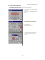
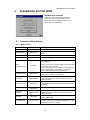
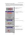
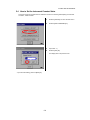
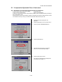
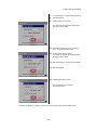
4.2 Setting Parameters
[Example setting]
S/A BUZZER: OFF
1
Press the [SETUP] icon.
2
Press the [MEASUREMENT] key.
3
Press the [NEXT] key three times.
4
Select the [OFF] button of S/A BUZZER.*1)
5
When the [SET] key is pressed, the setting will
be set and the SETUP MODE screen will
reappear.
*1)To return to the SETUP MODE screen, press the [EXIT] key.
4-3
5 CHECK AND ADJUSTMENT
5
CHECK AND ADJUSTMENT
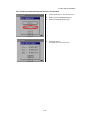
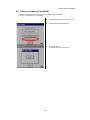
5.1 Checking and Adjusting of Instrument Constant
Normally, the instrument constant does not have discrepancy. It is recommended you measure and
compare with an accurately measured distance at a location where the precision is specifically
monitored on a consistent basis. If such a location is not available, establish your own base line over
20m (when purchasing the instrument) and compare the data measured with the newly purchased
instrument.
In both cases note that the setup displacement of the instrument position over the point, the prism,
baseline precision, poor collimation, atmospheric correction, and correction for refraction and earth
curvature determine the inspection precision. Please keep in mind these points.
Also, when providing a base line in a building, please note that differences in temperature greatly affect
the length measured.
If a difference of 5mm or over is the result from the comparative measurement, the following procedure
as shown below could be used to change the instrument constant.
1) Provide point C on a straight line, connecting straight line AB which is almost level and about 100m
long. Measure straight lines AB, AC and BC.
B
A
C
2) Obtain the instrument constant by repeating 1) above several times.
Instrument constant=AC+BC-AB
3) When there is error between written instrument constant value and calculated value, see section
5.4“How to Set the Instrument Constant Value” .
4) Once again, measure at a calibrated baseline and compare with the instrument base line the
length.
If using above procedure and no difference is found from the instrument constant at the factory or a
difference of over 5mm is found, contact TOPCON or your TOPCON dealer.
5-1
5 CHECK AND ADJUSTMENT
5.2 Checking the Optical Axis
To check if the optical axis of EDM and theodolite are matched, follow the procedure below. It is
especially important to check after adjustment of the eyepiece reticle is carried out.
1) Position the Instrument and prism with about 2m apart and face them at each other.
(At this time, the power is ON. )
Prism
about 2m
2) Sight through the eyepiece and focus to the prism. Then center the prism on the cross hairs.
Prism
3) Set to the measure mode to distance measurement or set audio.
4) Sight through the eyepiece and focus the (blinking) red light spot by turning the focusing knob in the
direction of infinity (clockwise). If displacement of the reticle cross hairs is within one-fifth of the
diameter of the round red light spot both vertically and horizontally, adjustment will not be required.
If displacement is more than one-fifth in the above case, and still remains so after rechecking
the original line of sight, the instrument must be adjusted by competent technicians. Please
contact TOPCON or your TOPCON dealer to adjust the instrument.
Red light spot
5-2
5 CHECK AND ADJUSTMENT
5.3 Checking/Adjusting the Theodolite Functions
● Pointers on the Adjustment
1) Adjust the eyepiece of the telescope properly prior to any checking operation which involves
sighting through the telescope.
Remember to focus properly, with parallax completely eliminated.
2) Carry out the adjustments in the order of item numbers, as the adjustments are dependent one
upon another. Adjustments carried out in the wrong sequence may even nullify previous
adjustment.
3) Always conclude adjustments by tightening the adjustment screws securely (but do not tighten them
more than necessary, as you may strip the threads, twist off the screw or place undue stress on the
parts).
Furthermore, always tighten by revolving in the direction of tightening tension.
4) The attachment screws must also be tightened sufficiently, upon completion of adjustments.
5) Always repeat checking operations after adjustments are made, in order to confirm results.
● Notes on the Tribrach
Note that the angle measuring precision may be effected directly if the tribrach has not been installed
firmly.
1) If any leveling screw becomes loose and slack or if collimation is unstable due to the looseness of
leveling screws, adjust by tightening the adjusting screws (in 2 places) installed over each leveling
screw with a screwdriver
2) If there is any slack between the leveling screws and the base, loosen the set screw of the holding
ring and tighten the holding ring with adjusting pin, until it is properly adjusted. Re-tighten the set
screw on completing the adjustment.
Adjustment screw
Leveling screw
Adjustment screw
Holding ring
Set screw
5-3
5 CHECK AND ADJUSTMENT
5.3.1 Checking /Adjusting the Plate Level
Adjustment is required if the axis of the plate level is not perpendicular to the vertical axis.
● Check
1) Place the plate level parallel to a line running through the centers of two leveling screws, say, A and
B. Use these two leveling screws only and place the bubble in the center of the plate level.
2) Rotate the instrument 180° or 200g around the vertical axis and check bubble movement of the
plate level. If the bubble has been displaced, then proceed with the following adjustment.
Plate level
Leveling screw B
Leveling screw A
● Adjustment
1) Adjust the level adjustment capstan screw, with the accessory adjusting pin and return the bubble
towards the center of the plate level. Correct only one-half of the displacement by this method.
2) Correct the remaining amount of the bubble displacement with the leveling screws.
3) Rotate the instrument 180° or 200g around the vertical axis once more and check bubble
movement. If the bubble is still displaced, then repeat the adjustment.
Level adjustment
capstan screw
Half amount of displacement
5.3.2 Checking /Adjusting the Circular Level
Adjustment is required if the axis of the circular level is also not perpendicular to the vertical axis.
● Check
1) Carefully level the instrument with the plate level only. If the bubble of the circular level is centered
properly, adjustment is not required. Otherwise, proceed with the following adjustment.
● Adjustment
1) Shift the bubble to the center of the circular level, by adjusting three capstan adjustment screws on
the bottom surface of the circular level, with the accessory adjusting pin.
Capstan adjustment
screws
Bottom of the base
5-4
5 CHECK AND ADJUSTMENT
5.3.3 Adjustment of the Vertical Cross-hair
Adjustment is required if the vertical cross-hair is not in a place perpendicular to the horizontal axis of
the telescope ( since it must be possible to use any point on the hair for measuring horizontal angles or
running lines).
● Check
1) Set the instrument up the tripod and carefully level it.
2) Sight the cross-hairs on a well defined Point A at a distance of, at least, 50 meters (160ft.) and
clamp horizontal motion.
3) Next swing the telescope vertically using the vertical tangent screw, and check whether the point
travels along the length of the vertical cross-hair.
4) If the point appears to move continuously on the hair, the vertical cross-hair lies in a plane
perpendicular to the horizontal axis ( and adjustment is not required ).
5) However, if the point appears to be displaced from the vertical cross-hair, as the telescope is swung
vertically, then proceed with the following adjustment.
● Adjustment
1) Unscrew the cross-hair adjustment section cover, by revolving it in the counterclockwise direction,
and take it off. This will expose four eyepiece section attachment screws.
Eyepiece section
attachment screws
Eyepiece section
attachment screws
Eyepiece
2) Loosen all four attachment screws slightly with the accessory screw-drive (while taking note of the
number of revolutions).
Then revolve the eyepiece section so that the vertical cross-hair coincides to Point A’.
Finally, re-tighten the four screws by the amount that they were loosened.
3) Check once more and if the point travels the entire length of the vertical cross-hair, further
adjustment is not required.
Perform following adjustment after completing the above adjustment .
Section 5.3.4 “Collimation of the Instrument”,
Section 5.3.6 “Adjustment of Vertical Angle 0 Datum”
5-5
5 CHECK AND ADJUSTMENT
5.3.4 Collimation of the Instrument
Collimation is required to make the line of sight of the telescope perpendicular to the horizontal axis of
the instrument, otherwise, it will not be possible to extend a straight line by direct means.
● Check
Eyepiece
1) Set the instrument up with clear
sights of about 50 to 60meters
(160 to 200 ft.) on both sides of the
instrument.
2) Level the instrument properly with the
plate level.
3) Sight Point A at approximately 50
meters (160 ft.) distance.
Telescope
4) Loosen the vertical motion clamp
only, and rotate the telescope 180° or
200g around the horizontal axis, so
that the telescope is pointed in the
opposite direction.
5) Sight Point B, at equal distance as
Point A and tighten the vertical
motion clamp.
6) Loosen the horizontal motion clamp
and rotate the instrument 180° or
200g around the vertical axis. Fix a
sight on Point A once more and
tighten the horizontal motion clamp.
7) Loosen the vertical motion clamp
only and rotate the telescope 180°
or 200g around the horizontal axis
once more and fix a sight on Point C,
which should coincide with previous
Point B.
8) If Points B and C do not coincide,
adjust in the following manner.
● Adjustment
1) Unscrew the cross-hair adjustment section cover.
2) Find Point D at a point between Points C and B, which should
be equal to 1/4th the distance between Points B and C and
measured from Point C. This is because the apparent error
between Points B and C is four times the actual error since
the telescope has been reversed twice during the checking
operation.
3) Shift the vertical cross-hair line and coincide it with
Point D, by revolving the left and right capstan
adjustment screws with the adjusting pin.Upon
completing the adjustment, repeat the checking
operation once more.
If Points B and C coincide, further adjustment is not
required. Otherwise , repeat the adjustment.
Capstan
adjustment
screws
Capstan
adjustment
screws
5-6
Eyepiece
5 CHECK AND ADJUSTMENT
First, loosen the capstan adjustment screw on the side to which the vertical cross-hair line
must be moved. Then tighten the adjustment screw on the opposite side by an equal amount
which will leave the tension of the adjustment screws unchanged.
Revolve in the counterclockwise direction to loosen and in the clockwise direction to tighten,
but revolve as little as possible.
Perform following adjustment after complete above adjustment .
Section 5.5.1 “Adjustment of Compensation Systematic Error of Instrument”.
Section 5.2 “Checking the Optical Axis”.
5.3.5 Checking / Adjusting the Optical Plummet Telescope
Adjustment is required to make the line of sight of the optical plummet telescope coincide with the
vertical axis ( otherwise the vertical axis will not be in the true vertical when the instrument is optically
plumbed).
● Check
1) Coincide the center mark and the point. (See Chapter 2 “PREPARATION FOR MEASUREMENT”.)
2) Rotate the instrument 180° or 200g around the vertical axis and check the center mark.
If the point is properly centered in the center mark, adjustment is not required. Otherwise, adjust in
the following manner.
● Adjustment
1) Take off the adjustment section cover of the optical plummet telescope eyepiece. This will expose
four capstan adjustment screws which should be adjusted with the accessory adjusting pin to shift
the center mark to the point. However, correct only one-half of the displacement in this manner.
Capstan
adjustment
screws
1/2 of displacement
Capstan
adjustment
screws
Eyepiece
Plummet telescope
2) Use the leveling screws and coincide the point and center mark.
3) Rotate the instrument 180° or 200g around the vertical axis once more and check the center mark.
If it is coincided to the point, then further adjustment is not required. Otherwise, repeat the
adjustment.
First, loosen the capstan adjustment screw on the side to which the center mark must be
moved. Then tighten the adjustment screw on the opposite side by an equal amount which
will leave the tension of the adjustment screws unchanged.
Revolve in the counterclockwise direction to loosen and in the clockwise direction to
tighten, but revolve as little as possible.
5-7
5 CHECK AND ADJUSTMENT
5.3.6 Adjustment of Vertical Angle 0 Datum
If when measuring the vertical angle of target A at telescope position normal (direct) and reverse
settings, the amount of normal and reverse measurements combined is other than 360° (ZENITH-0),
half of the difference from 360° is the error amount from corrected 0 setting. Carry out adjustment. As
adjustment for vertical angle 0 setting is the criteria for determining instrument coordinate origin, use
special care for adjustment.
1
5-8
2
Level the instrument properly with the
plate level.
Press the [ADJUST] icon.
3
Press the [V ANGLE 0 ADJUST] key.
4
Collimate target A from the telescope properly
in normal setting.
5
Press the [SET] key.
6
Collimate target A in reverse telescope setting.
7
Press the [SET] key.
Measured value is set and carry out
adjustment mode.
8
Check that the total amount of normal and
reverse angular travel is 360° collimating the
target A by normal and reverse positions.
5 CHECK AND ADJUSTMENT
5.4 How to Set the Instrument Constant Value
To set the Instrument constant which is obtained in section 5.1“Checking and Adjusting of Instrument
Constant” , follow as below.
1
Press the [ADJUST] icon from the main menu.
2
Press the [INST. CONSTANT] key.
3
4
Input value. * 1)
Press the [SET] key.
\
The display returns to previous menu.
*1)To cancel the setting, press the [EXIT] key.
5-9
5 CHECK AND ADJUSTMENT
5.5 Compensation Systematic Error of Instrument
5.5.1 Adjustment of Compensation Systematic Error of Instrument
1) Error of vertical axis (X,Y tilt sensor offset)
2) Collimation error
3) Error of vertical angle 0 datum
4) Error of horizontal axis
The above mentioned errors will be compensated by software, which calculated internally according to
each compensation value.
Also these errors can be compensated by software collimating one side of the telescope that is carried
out to delete the error by turning in normal and reverse both sides of telescope so far.
1
2
Level the instrument properly with the
plate level.
Press the [ADJUST] icon from the main menu.
3
Press the [3AXIS COMPENSATION] key.
4
Press the [ADJUST] key.
5
Collimate target A (around 0° in horizontal
within ±3°) in normal telescope setting.
6
Press the [SET] key ten times.
The number of measurements is displayed at
the top right of the display. *1)
5-10
5 CHECK AND ADJUSTMENT
7
8
Turn the telescope in reverse telescope setting.
Collimate target A.
9
Press the [SET] key ten times.
The number of measurements is displayed at
the top right of the display.
10 Collimate target B (more than ±10° from the
level ) in reverse telescope setting.
11 Press the [SET] key ten times.Å@
The number of measurements is displayed at
the top right of the display.
12 Turn the telescope in normal telescope setting.
13 Collimate target B.
14 Press the [SET] key ten times.
Then the display returns to 3AXIS
compensation menu.
*1)Pressing the [SKIP] key enables to set next step without changing the last compensated value.
5-11
5 CHECK AND ADJUSTMENT
5.5.2 Showing Compensation Systematic Error of Instrument
1
Press the [ADJUST] icon from the main menu.
2
3
Press the [3AXIS COMPENSATION] key.
Press the [CONSTANT DISPLAY] key.
4
Press the [EXIT] key.
The display returns to previous menu.
5-12
5 CHECK AND ADJUSTMENT
5.6 Reference Frequency Check Mode
The beam modulated by the reference frequency of EDM is emitted continuously.
This mode is used for frequency test mainly.
1
Press the [ADJUST] icon from the main menu.
2
Press the [FRQ CHECK MODE] key.
3
Press the [EXIT] key.
The display returns to previous menu.
5-13
6 SETTING ATMOSPHERIC CORRECTION
6
SETTING ATMOSPHERIC CORRECTION
The velocity of light through air is not constant and depends on the atmospheric temperature and
pressure. The atmospheric correction system of this instrument corrects automatically when the
correction value is set. 15°C/59°F, and 1013.25hPa / 760mmHg / 29.9 inHg is as a standard value for
0ppm in this instrument. The values are kept in the memory even after power is OFF.
6.1 Calculation of Atmospheric Correction
The followings are the correction formulas. Unit; meter
Ka: Atmospheric correction value
79.535 × P × 10 –6
P : Ambient atmospheric pressure (hPa)
K a = 279.67 – ------------------------273.15 + t
t : Ambient Atmospheric temperature (°C)
The distance L (m) after atmospheric correction is obtained as follow.
l :Measured distance when atmospheric
L = l (1+Ka)
correction is not set.
Example : In case Temperature +20°C, Air pressure 847hPa, l =1000 m
79.535 × 847 × 10 –6
Ka = 279.67 – ------------------------------
273.15 + 20
+ 50×10-6 (50 ppm)
L = 1000 (1+50×10-6 ) = 1000.050 m
6-1
6 SETTING ATMOSPHERIC CORRECTION
6.2 Setting of Atmospheric Correction Value
● How to Set Temperature and Pressure Value Directly
Measure the temperature and air pressure surrounding the instrument beforehand.
● Example : Temperature: +15°C, Pressure:1013.3 hPa
1
Turn the power switch on.
2
Press the [
3
Press the
[Prism constant value, Atmospheric correction]
icon.
4
Press the [TEMP.] icon.
5
Input Temp. value and Press. value.
] key.
[Prism constant value, Atmospheric correction] icon
[TEMP.] icon
[ENTER] key
[Example]
6
Temp. : +15.0°C
Press. : 1013.3hPa.
Press the [ENTER] key.
*1)Range :
Temp.
-30.0 °C to +60.0 °C (0.1 °C step) ,
-22.0 °F to +140.0 °F (0.1 °F step)
Press.
560.0 to 1066.0hPa (0.1hPa step) ,
420.0 to 800.0mmHg (0.1mmHg step) ,
16.5 to 31.5inHg (0.1inHg step)
*2)When the atmospheric correction value, which is calculated from the input temperature and pressure
values, exceeds the range ± 999.9ppm, the operating procedure returns to step 4 automatically. Input
values again.
6-2
6 SETTING ATMOSPHERIC CORRECTION
● How to Set the Atmospheric Correction Value Directly
Measure the temperature and air pressure to find atmospheric correction value(PPM) from the chart or
correction formula.
1
Turn the power switch on.
2
Press the [
3
Press the
[Prism constant value, Atmospheric correction]
icon.
4
Press the [PPM] icon.
5
Input atmospheric correction value. *1)
6
Press the [ENTER] key.
] key.
[Prism constant value, Atmospheric correction] icon
[PPM] icon
*1)Input range : -999.9mm ~ +999.9mm (0.1mm step)
6-3
6 SETTING ATMOSPHERIC CORRECTION
Atmospheric Correction Chart (For your reference)
The atmospheric correction value is obtained easily with the atmospheric correction chart. Find the
measured temperature in horizontal, and pressure in vertical on the chart.
Read the value from the diagonal line, which represents the required atmospheric correction value.
Example:
The measured temperature is +26°C
The measured pressure is 1013 hPa
There fore,
The correction value is +10ppm
6-4
6 SETTING ATMOSPHERIC CORRECTION
6-5
6 SETTING ATMOSPHERIC CORRECTION
6-6
7 CORRECTION FOR REFRACTION AND EARTH CURVATURE
7
CORRECTION FOR REFRACTION AND EARTH
CURVATURE
The instrument measures distance, taking into account correction for refraction and earth curvature.
7.1 Distance Calculation Formula
Distance Calculation Formula; with correction for refraction and earth curvature taken into account.
Follow the Formula below for converting horizontal and vertical distances.
Horizontal distance D = AC(α) or BE(β)
Vertical distance Z =BC(α) or EA(β)
D = L{cosα–(2θ – γ ) sinα}
Z = L{sinα+(θ – γ ) cosα}
θ = L.cosα/2R........... Earth curvature
correcting item
γ =K•Lcosα/2R....... Atmospheric
refraction
correcting item
K =0.14 or 0.2.......... Coefficient of
refraction
R =6372km.............. Radius of earth
α ( or β)................... Altitude angle
L .............................. Slope distance
● The conversion formula for horizontal and vertical distances is as follows when correction for
refraction and earth curvature is not applied.
D=L•cosα
Z=L•sinα
The coefficient of the instrument has been set at 0.14 before shipment (K=0.14).
if the "K" value is to be changed, refer to 4 “PARAMETERS SETTING MODE”.
7-1
8 POWER SOURCE AND CHARGING
8
POWER SOURCE AND CHARGING
8.1 On-board Battery BT-61Q
● To remove
1 Pull the battery cover lever and open the cover.
2 Remove the battery.
CHARGE LED
POWER LED
BT-61Q
Battery cover lever
AC-cable
BC-30
Battery
● To charge
1 Connect the AC-Cable to the charger.
2 Plug the AC-Plug into the outlet. (The POWER LED will light.)
3 Attach the battery in the charger. Charging will start. (The CHARGE LED will light.)
Charging will take approximately 4 hours. (The CHARGE LED will go out.)
4 After charging, remove the battery from the charger.
Remove the charger from the outlet.
The POWER LED
Red ON
:
Power is on.
The CHARGE LED will indicate charging status;
On Solid
: Wait for charging.
Red ON
: Charging.
On Solid
: Charging completed.
Red Flashing : Charging error.
CHARGE LED will flash when the battery life is over or the battery is
broken down. Replace the battery to new one.
● To install
1 Place the battery to the instrument.
2 Shut the battery cover until click sound can be heard.
8-1
8 POWER SOURCE AND CHARGING
● Do not charge continuously, otherwise the battery and the charger may be deteriorated.
If charging is necessary, use the charger after stopping charge for approximately 30 minutes.
● Do not charge the battery in right after the battery is charged, it causes deterioration of the battery
in rare cases.
● The charger may develop heat while charging, there is no problem of it.
1
2
3
4
5
Recharging should take place in a room with an ambient temperature range of 10°C to
40°C (50°F to 104°F).
If charging is done at high temperature, charging time of the battery may take longer.
Exceeding the specified charging time may shorten the life of the battery and should be
avoided if possible.
The battery source will discharge when stored and should be checked before using with
instrument .
If you allow the battery to be completely discharged, it will have an effect on the overall
performance for proper charging in the future.
Keep batteries charged at all times..
8-2
9 DETACH/ATTACH OF TRIBRACH
9
DETACH/ATTACH OF TRIBRACH
The instrument is easily detached or attached to the tribrach, with a tribrach locking lever loosened or
tightened for this purpose.
● Detachment
1) Loosen the tribrach locking lever, by revolving it 180° or 200g in the counterclockwise direction
(which will point the triangle mark upwards).
2) Grip the carrying handle firmly with one hand while holding the tribrach with the other. Then lift the
instrument straight upwards and off.
● Attachment
1) Hold the instrument by the carrying handle, with one hand, and carefully lower it on top of the
tribrach while, at the same time, coinciding the alignment piece with the tribrach alignment groove
on the instrument and tribrach respectively.
2) When fully seated, revolve the tribrach locking lever 180° or 200g clockwise ( which will point the
triangle mark downwards again).
Alignment piece
Alignment groove
Securing screw
Tribrach locking lever
● Locking the Tribrach Locking Lever
The tribrach locking lever can be locked, to prevent it be accidentally removed, especially if the upper
instrument section is not being detached very often. Simply tighten the securing screw on the locking
lever with the accessory screwdriver, found in the case.
9-1
10 SPECIAL ACCESSORIES
10
SPECIAL ACCESSORIES
Battery charger BC-6 (for BT-3L)
● Input voltage:100, 120, 220, 240V
AC: ±10% 50/60 Hz
● Power consumption: 15VA approx.
● Charging time:
approx. 15 hour (+20°C) to charge BT-3L
● Operation temperature range:
+10°C to +40°C (+50 to +104°F)
● External dimensions:
142(L) × 96(W) × 64(H) mm
● Weight:1.0kg
Auto converter AC-6
● Input voltage:12V DC
● Output voltage :DC 8.4V
● Cable length:3m approx.
● External dimensions:
100(L)×50(W)×52(H) mm
● Weight:0.3kg
Power cord PC-5
(For AC-6 and TOPCON FC series Data collector)
● L-shape plug provided
● Cord length: 2m approx.
Large capacity battery pack BT-3L
● Output voltage : DC 8.4V
● Capacity: 6Ah
● External dimensions:
190(L) × 106(W) × 74(H) mm
● Weight:2.8kg
Diagonal eyepiece, Model 10
Power cord PC-6 (For AC-6 and BT-3L)
Observation in an easy posture will be provided up to the ● L-shape plug provided
zenith position
● Cord length: 2m approx.
Trough compass, Model 6
Shock proof construction. No clamp is necessary when
carrying the instrument.
10-1
Solar reticle, Model 6
A reticle designed for collimation of the sun.
Can be used together with Solar Filter.
10 SPECIAL ACCESSORIES
Solar filter, Model 6
A filter designed exclusively for direct collimation of the
sun.
Solar filter of flap-up type.
Optical plummet tribrach
This is detachable tribrach having built-in optical
plummet telescope.
(Compatible with Wild)
Mini prism
The mini prism (25.4mm) is made from precision ground
glass and mounted in high impact plastic housings.
The mini has the unique capability of being positioned
either at a "0" or "–30" with the same prism.
Prism unit case, Model 6
Fixed 9 prisms unit or tilting 3 prisms unit can be
stored in this case. Especially, this is a very easy
case to carry. Soft material is used.
● External dimensions:
250(L)×120(W)×400(H) mm
● Weight:0.5kg
Prism sets
See the description on Chapter 12 “PRISM SYSTEM”
Prism unit case, Model 5
1 prisms unit or fixed 3 prisms unit can be stored in
this case. Especially, this is a very easy case to
carry. Soft material is used.
● External dimensions:
200(L)×200(W)×350(H) mm
● Weight:0.5kg
Gadget case, Model 1
A case to store and carry accessories.
● External dimensions:
300(L)×145(W)×220(H) mm
● Weight:1.4kg
10-2
10 SPECIAL ACCESSORIES
Back pack, Model 2
Convenient for use in mountainous terrain.
Prism unit case, Model 3
This is the plastic case to store and carry various
sets of prisms.
The case covers one of the following prism sets:
● Tilt single prism set
● Tilt single prism set with a target plate
● Fixed triple prism unit
● Fixed triple prism unit with a target plate
● External dimensions:
427(L)×254(W)×242(H) mm
● Weight:3.1kg
Aluminum extension leg tripod, Type E
● Flat head 5/8" × 11 threads with adjustable legs.
Wide-frame extension leg tripod, Type E (Wood)
● Flat head 5/8" × 11 threads with adjustable legs.
10-3
11 BATTERY SYSTEM
11
BATTERY SYSTEM
In case of On-board battery
In case of External battery
BT-3L
PC-6
PC-5
PC-6
BT-61Q
GTS-720 series
Car battery
GTS-720 series
AC-6
Charging
Charging time
BC-30
Approx. 4h
Quick
For AC100V~240V use
BT-61Q
Approx.15h
BC-6
BT-3L
11-1
Normal
for AC 100V / 120V / 220V
/ 240V use
12 PRISM SYSTEM
12
PRISM SYSTEM
Arrangement according to your needs is possible.
Target pole-2
(not used with 9 prisms)
Prism-2
Tilting prism
holder-2
with target
plate-2
Tilting prism Single prism
holder-3
holder-2
Triple prism
holder-2
Tribrach
adaptor-2
Tilting triple
prism holder-1 9 prism
holder-2
Tribrach
adaptor-S2
Pole adaptor- A
Pole adaptor- F2
Tribrach
Optical plummet tribrach
It is possible to change the combination according purpose.
Tilt single prism unit
Fixed 3 prisms unit
Fixed 9 prisms unit
Tripod
Use the above prisms after setting them at the same height as the instruments.To adjust the height of
prism set, change the position of 4 fixing screws.
12-1
13 PRECAUTIONS
13
PRECAUTIONS
1) For transportation, hold by the handle or yoke of the instrument. Never hold by the lens barrel as it
can affect the fixing bracket inside and reduce the accuracy of the instrument.
2) Never expose the instrument without a filter to direct sunlight. It may damage the components
inside the instrument.
3) Never leave the instrument unprotected in high temperature. The temperature inside instrument
may easily reach up to 70°C or above and will reduce the service life.
4) When a high degree of precision is required for measurement, provide shade against direct sunlight
for the instrument and tripod.
5) Any sudden change of temperature to the instrument or prism may result in a reduction of
measuring distance range, i.e. when taking the instrument out from a heated vehicle.
6) When opening the carrying case and taking out the instrument, place the case horizontally, then
open the case.
7) When returning the instrument to its case, be sure to match the white positioning marks provided
with the case and place the instrument.
8) For transportation, provide dampening or a cushion appropriately to avoid sudden shock or
vibration.
9) For cleaning the instrument after use, remove dust using a cleaning brush, then wipe off with a
cloth.
10) For cleaning the lens surface, use a cleaning brush to remove the dust, then use a clean lintless
cotton cloth. Moisten it with alcohol ( or mixture with ether ) to wipe gently in a rotational motion
from the center out.
11) Even if any abnormality occurs, never attempt to disassemble or lubricate the instrument yourself.
Always consult with TOPCON or your dealer.
12) To remove the dust on the case, never use thinner or benzine. Use a clean cloth moistened with
neutral detergent.
13) Check each part of the tripod after extended use. Parts (screws or clamps) may work themselves
free.
13-1
14 ERROR DISPLAYS
14
ERROR DISPLAYS
14.1 Message
Description
Countermeasures
[Please Input Value!]
Input numerical value.
[Please Input Exact Value!]
Input exact numerical value.
[Please Input Exact Command!]
Input exact command.
[V Angle 0Set Error(Step1)]
V angle 0-set is over. (in normal telescope)
[V Angle 0Set Error(Step2)]
V angle 0-set is over. (in reverse telescope)
[V Angle 0Set Over(Total)]
V angle 0-set is over.
(in normal and reverse telescope)
[V Angle Range Over]
Press the [Yes] key : Data is outputted
Press the [No] key : Cancel
V angle range is over.
[V Angle Offset Range Over]
V angle offset range is over.
[V Angle Tilt Offset Range Over]
V angle tilt offset range is over.
[Collimation constant Range Over]
Collimation constant range is over.
[Horizontal angle axis constant Range Over]
Horizontal angle axis constant range is over.
[The unit of an angle is wrong]
The unit of a set angle is wrong.
[DATA OUT?]
● If error still persist after attempting to clear them, contact your local Topcon dealer or Topcon head
office.
14.2 Error
Description
Contents
[Data Read Error 01~19]
The data could not be loaded.
[Data Set Error 01~10]
The data could not be set.
[EDM Offset Read Error]
The EDM offset could not be loaded.
[EDM Offset Set Error]
The EDM offset could not be set.
[XTILT OVER]
The external communication could not be
accomplished.
X tilt is over. ( ±4’ )
[YTILT OVER]
Y tilt is over. ( ±4’ )
[Ext Communication Retry Error]
Displayed when the instrument rotated too
fast or any abnormality occurs in angle
measuring system .
Displayed when the telescope rotated too
fast or any abnormality occurs in angle
measuring system.
[H-Angle Error]
[V-Angle Error]
Any abnormality occurs with Tilt sensor.
Repair is required.
Any abnormality occurs with EDM (distance
measuring system).
Repair is required.
Restart and confirm the operation procedure
is correct.
Repair is required.
[Tilt Error]
[E-60’]
[E-86]
[E-99]
14-1
15 SPECIFICATIONS
15
SPECIFICATIONS
Telescope
Length
Objective lens
Magnification
Image
Field of view
Resolving power
Minimum focus
Reticle illumination
:
:
:
:
:
:
:
:
150mm
45mm (EDM 50mm)
30×
Erect
1°30'
2.5"
1.3m
Provided
Distance measurement
Measurement range
Atmospheric conditions
Model
Prism
Condition 1
Mini prism
GTS-721
GTS-722
GTS-723
----
1 prism
3,000m (9,900ft)
3,500m (11,500ft)
3 prisms
4,000m (13,200ft)
4,700m (15,400ft)
9 prisms
5,000m (16,400ft)
5,800m (19,000ft)
Mini prism
GTS-725
1,000m (3,300ft)
Condition 2
1 prism
900m (3,000ft)
2,000m (6,600ft)
---2,300m (7,500ft)
3 prisms
2,700m (8,900ft)
3,100m (10,200ft)
9 prisms
3,400m (11,200ft)
4,000m (13,200ft)
Condition 1: Sight haze with visibility about 20km (12.5miles) moderate sunlight with light heat
shimmer.
Condition 2: No haze with visibility about 40km(25 miles), overcast with no heat shimmer.
Measurement accuracy
: ±(2mm +2ppm × D) m.s.e.
D:Measuring distance (mm)
Least Count in Measurement
Fine measurement mode
Coarse measurement mode
Tracking measurement mode
Measurement Time
Fine measurement mode
Coarse measurement mode
Tracking measurement mode
Atmospheric Correction Range
Prism Constant Correction Range
Coefficient Factor
: 1mm (0.005ft.) / 0.2mm (0.001ft.)
: 1mm (0.005ft.) /10mm (0.02ft.)
: 10mm (0.02ft.)
: 1mm
: Approx. 1.2sec. (Initial 4 sec.)
0.2mm : Approx. 2.8 sec. (Initial 5 sec.)
: Approx. 0.7sec. (Initial 3 sec.)
: Approx. 0.4sec. (Initial 3 sec.)
(The initial time will be different by a condition and
setting EDM off time. )
: –999.9 ppm to +999.9 ppm, in 0.1 ppm increments
: –99.9 mm to +99.9 mm, in 0.1 mm increments
: Meter / Feet
International feet
1meter = 3.2808398501 ft.
US SURVEY feet
1meter = 3.2808333333 ft.
15-1
15 SPECIFICATIONS
Electronic Angle Measurement
Method
Detecting system :
Horizontal
Vertical
: Absolute reading
: 2 sides
: 2 sides
Minimum reading
GTS-721
GTS-722/723/725
: 1"/0.5" (0.5mgon/0.1mgon, 5mmil/2mmil) reading
: 5"/1" (1mgon/0.2mgon, 20mmil/ 5mmil) reading
Accuracy(Standard deviation based on DIN 18723 )
GTS-721
: 1"(0.3mgon )
GTS-722
: 2"(0.6mgon )
GTS-723
: 3"(1.0mgon )
GTS-725
: 5"(1.5mgon )
Diameter of circle
: 71 mm
Tilt Correction
Type
Method
Compensating Range
Correction unit
:
:
:
:
Computer unit
Microprocessor
Processor speed
Operating system
Memory
:
:
:
:
Display
LCD
Automatic vertical and Horizontal index
Liquid type
±4'
1"(0.1mgon)
SH7750R
177MHz
Microsoft Windows CE.NET 4.2
64MB / RAM
64MB Flash disk (Internal)
: 3.5 inch TFT color LCD
(240x320 dots )
: Electrical analog resistor thin film system
Touch panel
Others
Instrument height
: 182mm (7.2in) Base unit detachable
(Height from the tribrach dish to the center of
telescope)
Level sensitivity
Circular level
Plate level
: 10'/2mm
: 30"/2 mm
Optical Plummet Telescope
Magnification
Focusing range
Image
Field of view
:
:
:
:
3×
0.5m to infinity
Erect
4°
Laser Plummet (only for Laser plummet type)
Light source
Wave length
Out put
Laser class
:
:
:
:
LD (Visible laser)
633nm
1mW maximum
CLASS 2 (ll) laser product
CompactFlash* Card Slot
: Based on CompactFlash (Type I/II)*
*CompactFlash is a trademark of SanDisk corporation.
15-2
15 SPECIFICATIONS
Dimension
Weight
Instrument
(GTS-721, 722, 723)
: 343 (H) × 245 (W)× 219 (L) mm
(13.5 (H) × 9.6 (W) × 8.6 (L) in)
(GTS-725)
: 343 (H) × 245 (W)× 199 (L) mm
(13.5 (H) × 9.6 (W) × 7.8 (L) in)
(GTS-721, 722, 723)
: 6.2 kg (13.6 lbs) (With battery)
(GTS-725)
: 6.1 kg (13.4 lbs) (With battery)
Carrying case
Durability
Protection against water and dust
Ambient Temperature Range
: 4.7kg (10.3 lbs)
: IP54 (Based on the standard IEC60529)
: –20°C to +50°C (–4°F to +122°F)
Rechargeable Battery BT-61Q (This battery does not contain mercury.)
Out put voltage
: DC7.4 V
Capacity
: 4400mAh
Maximum operating time (when fully recharged) at +20°C (+68°F)
Including distance measurement
: 7.5hours
Angle measurement only
: 10hours
Weight
Battery Charger BC-30
Input voltage
Frequency
Recharging time (at +20°C /+68°F)
Battery BT-61Q
Operating temperature
Charging signal
Finishing signal
Weight
: 0.2kg ( 0.4 lbs)
: AC 100-240V
: 50/60Hz
:
:
:
:
:
4 hours
+10°C to +40°C ( +50°F to 104°F)
Red charge lamp should glow
Red charge lamp should go out
0.15kg (0.3 lbs)
● Battery using time will vary depending on environmental conditions and operations done with
GTS-720 series.
15-3
APPENDIX
APPENDIX
1
Dual Axis Compensation
Inclination of the vertical axis with respect to true vertical will result in incorrectly measured horizontal
angles. The extent of the error in horizontal angle measurement due to axis tilt depends on three
factors :
● the amount of the tilt of axis
● the elevation of the target
● the horizontal angle between the direction of till of the vertical axis and the target.
These factors are related by the following formula :
Hz err = V•sinα • tanh
where v = tilt of axis in arcseconds
α = azimuth angle between vert. axis direction and target
h = elevation of target
Hzerr = error in horizontal angle
Example: When the vertical axis is tilted by 30 arcseconds, the target is 10° above the horizon and
rotated 90 in azimuth from the direction of the vertical axis error.
Hzerr = 30" • sinα • tan10°
Hzerr = 30" • 1 • 0 .176326=5.29"
From the above example it can be seen that horizontal angle errors will increase with steeper vertical
sights (tangent will increase as vertical angle increases) and will be at a maximum when the target is at
right angles (sin 90°=1) to the direction of the vertical axis error. Errors will be at a minimum when the
sights are nearly horizontal (h=0, tan0=0) and in the same direction as the vertical axis error ( α =0,
sin0=0). Please refer to the table below to see the relationship between axis tilt (v) and elevation (h) and
the error in horizontal angles which results from these factors.
h
0°
1°
5°
10°
30°
45°
V
0"
0"
0"
0"
0"
0"
0"
5"
0"
0.09"
0.44"
0.88"
2.89"
5"
10"
0"
0.17"
0.87"
1.76"
5.77"
10"
15
0"
0.26"
1.31"
2.64"
8.66"
15"
30"
0"
0.52"
2.62"
5.29"
17.32"
30"
1'
0"
1.05"
5.25"
10.58"
34.64"
1'
APPENDIX-1
APPENDIX
It is clear from the table that dual axis compensation has the most benefit when the elevation
of the target is greater then 30° and the axis is tilted more than 10". The entries indicated in
bold in the table show, in fact, that for many common surveying applications i.e. target elevation
<30° and axis error <10", virtually no correction would be required. Dual axis compensation is
especially suited then for applications where the sights are very steep.
Even though the compensators can correct horizontal angles for vertical axis errors,
it is still important to use care in setting up the instrument.
Centering error, for instance, cannot be corrected by the compensators. If the vertical axis is
tilted by 1’ with the instrument 1.4meters above the ground, a centering error of approx. 0.4mm
will result. The maximum effect of this error at 10m is about 8" of horizontal angle error.
In order to maintain the increased accuracy possible through dual axis compensation, it is
necessary to keep the compensators in proper adjustment.The compensators must agree with
the actual level condition of the instrument. Through various environmental stresses, the
agreement between the level condition sensed by the compensators and the true level condition
of the instrument may be disturbed. In order to reestablish the correct relationship between the
compensator and the true level condition of the instrument, it is necessary to carry out the
vertical indexing procedure listed on Section 5.3.6“Adjustment of Vertical Angle 0 Datum” . This
adjustment will both reset the vertical index (cause a direct + indirect zenith reading to the same
elevation to equal 360°) and zero the level reference for the horizontal compensator. While
correct vertical angles can be obtained by averaging direct and indirect reading even when the
index is improperly adjusted, the same is not true for horizontal angles. Since the vertical axis
error is fixed for a given setup, its effect cannot be removed by averaging two readings.
For this reason, it is extremely important to maintain the vertical indexing adjustment to
insure proper correction of the horizontal angles.
APPENDIX-2
APPENDIX
APPENDIX-3
ELECTRONIC TOTAL STATION
GTS-720 series
TOPCON POSITIONING SYSTEMS, INC.
5758 West Las Positas Blvd., Pleasanton, CA 94588, U.S.A.
Phone: 925-460-1300 Fax: 925-460-1315 www.topcon.com
TOPCON CALIFORNIA
3380 Industrial Blvd, Suite 105, West Sacramento, CA 95691, U.S.A.
Phone: 916-374-8575 Fax: 916-374-8329
TOPCON SOUTH ASIA PTE. LTD.
Blk 192 Pandan Loop, #07-01 Pantech Industrial Complex, Singapore 128381
Phone: 62780222 Fax: 62733540 www.topcon.com.sg
TOPCON AUSTRALIA PTY. LTD.
408 Victoria Road, Gladesville, NSW 2111, Australia
Phone: 02-9817-4666 Fax: 02-9817-4654 www.topcon.com.au
TOPCON INSTRUMENTS (THAILAND) CO., LTD.
TOPCON EUROPE B.V.
Essebaan 11, 2908 LJ Capelle a/d IJssel, The Netherlands.
Phone: 010-4585077 Fax: 010-4585045 www.topconeurope.com
IRELAND OFFICE
Unit 69 Western Parkway Business Center
Lower Ballymount Road, Dublin 12, Lreland
Phone: 01460-0021 Fax: 01460-0129
77/162 Sinn Sathorn Tower, 37th Fl.,
Krungdhonburi Rd., Klongtonsai, Klongsarn, Bangkok 10600 Thailand.
Phone: 02-440-1152~7 Fax: 02-440-1158
TOPCON INSTRUMENTS (MALAYSIA) SDN. BHD.
TOPCON DEUTSCHLAND G.m.b.H.
Giesserallee 31, 47877 Willich, GERMANY
Phone: 02154-885-100 Fax: 02154-885-111 [email protected]
www.topcon.de
TOPCON S.A.R.L.
89, Rue de Paris, 92585 Clichy, Cedex, France.
Phone: 33-1-41069490 Fax: 33-1-47390251 [email protected]
TOPCON ESPAÑA S.A.
Excella Business Park Block C, Ground & 1st Floor, Jalan Ampang Putra,
Taman Ampang Hilir, 55100 Kuala Lumpur, MALAYSIA
Phone: 03-42701068 Fax: 03-42704508
TOPCON KOREA CORPORATION
2F Yooseoung Bldg., 1595-3, Seocho-Dong, Seocho-gu, Seoul, 137-876, Korea.
Phone: 82-2-2055-0321 Fax: 82-2-2055-0319 www.topcon.co.kr
TOPCON OPTICAL (H.K.) LIMITED
2/F., Meeco Industrial Bldg., No. 53-55 Au Pui Wan Street, Fo Tan Road,
Shatin, N.T., Hong Kong
Phone: 2690-1328 Fax: 2690-2221 www.topcon.com.hk
Frederic Mompou 5, ED. Euro 3, 08960, Sant Just Desvern, Barcelona, Spain. TOPCON CORPORATION BEIJING OFFICE
Phone: 93-473-4057 Fax: 93-473-3932 www.topconesp.com
Room 8A Poly Plaza Building, 14 Dongzhimen Nandajie,
TOPCON SCANDINAVIA A. B.
Dongcheng District, Beijing, 100027, China
Phone: 10-6501-4191~2 Fax: 10-6501-4190
Neongatan 2 S-43151 Mölndal, SWEDEN
Phone: 031-7109200 Fax: 031-7109249
TOPCON CORPORATION BEIRUT OFFICE
TOPCON (GREATBRITAIN) LTD.
Topcon House Kennet Side, Bone Lane, Newbury, Berkshire RG14 5PX U.K.
Phone: 44-1635-551120 Fax: 44-1635-551170
[email protected] [email protected]
P. O. BOX 70-1002 Antelias, BEIRUT-LEBANON.
Phone: 961-4-523525/961-4-523526 Fax: 961-4-521119
TOPCON CORPORATION DUBAI OFFICE
C/O Atlas Medical FZCO., P. O. Box 54304, C-25, Dubai Airport Free Zone,UAE
Phone: 971-4-2995900 Fax: 971-4-2995901
TOPCON CORPORATION
75-1 Hasunuma-cho, Itabashi-ku, Tokyo 174-8580, Japan
Phone: 3-3558-2520 Fax: 3-3960-4214 www.topcon.co.jp
64541 90012 GTS-720 [standard]
0310(1a)