1
CCII Systems (Pty) Ltd Registration No. 1990/005058/07
C ommunications
C omputer I ntellig ence
I nteg ration
Generic User Manual
for the
FDDI Adapter
VxWorks BIT Application
C²I² Systems Document No.
CCII/FDDI/6-MAN/003
Document Issue
1.2
Issue Date
2009-08-20
Print Date
2009-08-20
File Name
P:\FDDI\TECH\MAN\CFDMAN03.WPD
Distribution List No.
DN 0090
© C²I² Systems The copyright of this document is the property of C²I² Systems. The document is issued for the sole
purpose for which it is supplied, on the express terms that it may not be copied in whole or part, used by
or disclosed to others except as authorised in writing by C²I² Systems.
Document prepared by C²I² Systems, Cape Town
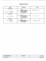
Signature Sheet
Name
Signature
Date
Completed by
Project Engineer
Board Level Products
C²I² Systems
Accepted by
Project Manager
Board Level Products
C²I² Systems
Accepted by
Quality Assurance
C²I² Systems
CCII/FDDI/6-MAN/003
CFDMAN03.WPD
2009-08-20
Issue 1.2
Page ii of vi
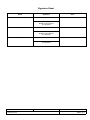
Amendment History
Issue
Description
Date
ECP No.
-
1.0
Initial version based on Dy4 document.
2000-11-28
1.1
Correct documentation errors in Figure 2 and in Section 5.7.
2002-10-22
1.2
Improve document naming consistency.
2009-08-20
CCII/FDDI/6-MAN/003
CFDMAN03.WPD
2009-08-20
CCII/FDDI/6-ECP/035
Issue 1.2
Page iii of vi
Contents
1.
Scope . . . . . . . . . . . . . . . . . . . . . . . . . . . . . . . . . . . . . . . . . . . . . . . . . . . . . . . . . . . . . . . . . . . 1
1.1
1.2
2.
Applicable and Reference Documents . . . . . . . . . . . . . . . . . . . . . . . . . . . . . . . . . . . . . . . . . 2
2.1
2.2
3.
To Build the BIT Application into the VxWorks Kernel
..................................3
To Build the FDDI Software Driver and BIT Application into the VxWorks Kernel
...............3
To Load the BIT Application Separately . . . . . . . . . . . . . . . . . . . . . . . . . . . . . . . . . . . . . . . . . . . . . . . . . . . 3
Platform Specific Variations . . . . . . . . . . . . . . . . . . . . . . . . . . . . . . . . . . . . . . . . . . . . . . . . . . . . . . . . . . . . . 4
Application Program Interface (API) . . . . . . . . . . . . . . . . . . . . . . . . . . . . . . . . . . . . . . . . . . 5
4.1
4.2
4.3
5.
Applicable Documents . . . . . . . . . . . . . . . . . . . . . . . . . . . . . . . . . . . . . . . . . . . . . . . . . . . . . . . . . . . . . . . . . 2
Reference Documents . . . . . . . . . . . . . . . . . . . . . . . . . . . . . . . . . . . . . . . . . . . . . . . . . . . . . . . . . . . . . . . . . 2
Installation Procedure . . . . . . . . . . . . . . . . . . . . . . . . . . . . . . . . . . . . . . . . . . . . . . . . . . . . . . 3
3.1
3.2
3.3
3.4
4.
Identification . . . . . . . . . . . . . . . . . . . . . . . . . . . . . . . . . . . . . . . . . . . . . . . . . . . . . . . . . . . . . . . . . . . . . . . . . 1
System Overview . . . . . . . . . . . . . . . . . . . . . . . . . . . . . . . . . . . . . . . . . . . . . . . . . . . . . . . . . . . . . . . . . . . . . 1
BIT Functions . . . . . . . . . . . . . . . . . . . . . . . . . . . . . . . . . . . . . . . . . . . . . . . . . . . . . . . . . . . . . . . . . . . . . . . . 5
4.1.1 int ccfddiInitBIT (cc_test_message_style_type init_messages_style) . . . . . . . . . . . . . . . . . . . . . . 5
4.1.2 int ccfddiPOST (cc_tests_type *post_tests, cc_tests_report_type *post_results) . . . . . . . . . . . . . 5
4.1.3 int ccfddiTest (cc_tests_type *tests, cc_tests_report_type *results) . . . . . . . . . . . . . . . . . . . . . . . . 5
4.1.4 int ccfddiShowTestResults (cc_tests_report_type *results) . . . . . . . . . . . . . . . . . . . . . . . . . . . . . . 5
BIT Data Types . . . . . . . . . . . . . . . . . . . . . . . . . . . . . . . . . . . . . . . . . . . . . . . . . . . . . . . . . . . . . . . . . . . . . . 6
4.2.1 cc_test_message_style_type . . . . . . . . . . . . . . . . . . . . . . . . . . . . . . . . . . . . . . . . . . . . . . . . . . . . . 6
4.2.2 cc_run_status_type . . . . . . . . . . . . . . . . . . . . . . . . . . . . . . . . . . . . . . . . . . . . . . . . . . . . . . . . . . . . 6
BIT Data Structures . . . . . . . . . . . . . . . . . . . . . . . . . . . . . . . . . . . . . . . . . . . . . . . . . . . . . . . . . . . . . . . . . . . 6
4.3.1 cc_test_option_type . . . . . . . . . . . . . . . . . . . . . . . . . . . . . . . . . . . . . . . . . . . . . . . . . . . . . . . . . . . . 6
4.3.2 cc_test_result_type . . . . . . . . . . . . . . . . . . . . . . . . . . . . . . . . . . . . . . . . . . . . . . . . . . . . . . . . . . . . . 7
4.3.3 cc_tests_type . . . . . . . . . . . . . . . . . . . . . . . . . . . . . . . . . . . . . . . . . . . . . . . . . . . . . . . . . . . . . . . . . 7
4.3.4 Application Example . . . . . . . . . . . . . . . . . . . . . . . . . . . . . . . . . . . . . . . . . . . . . . . . . . . . . . . . . . . . 8
Test Descriptions . . . . . . . . . . . . . . . . . . . . . . . . . . . . . . . . . . . . . . . . . . . . . . . . . . . . . . . . . 10
5.1
5.2
5.3
5.4
5.5
5.6
5.7
5.8
PROM Check . . . . . . . . . . . . . . . . . . . . . . . . . . . . . . . . . . . . . . . . . . . . . . . . . . . . . . . . . . . . . . . . . . . . . . . 10
5.1.1 Description . . . . . . . . . . . . . . . . . . . . . . . . . . . . . . . . . . . . . . . . . . . . . . . . . . . . . . . . . . . . . . . . . . 10
5.1.2 Test Coverage . . . . . . . . . . . . . . . . . . . . . . . . . . . . . . . . . . . . . . . . . . . . . . . . . . . . . . . . . . . . . . . 10
Timer and Hardware Interrupt Request (IRQ) . . . . . . . . . . . . . . . . . . . . . . . . . . . . . . . . . . . . . . . . . . . . . . 10
5.2.1 Description . . . . . . . . . . . . . . . . . . . . . . . . . . . . . . . . . . . . . . . . . . . . . . . . . . . . . . . . . . . . . . . . . . 10
5.2.2 Test Coverage . . . . . . . . . . . . . . . . . . . . . . . . . . . . . . . . . . . . . . . . . . . . . . . . . . . . . . . . . . . . . . . 10
FORMAC Register . . . . . . . . . . . . . . . . . . . . . . . . . . . . . . . . . . . . . . . . . . . . . . . . . . . . . . . . . . . . . . . . . . . 11
5.3.1 Description . . . . . . . . . . . . . . . . . . . . . . . . . . . . . . . . . . . . . . . . . . . . . . . . . . . . . . . . . . . . . . . . . . 11
5.3.2 Test Coverage . . . . . . . . . . . . . . . . . . . . . . . . . . . . . . . . . . . . . . . . . . . . . . . . . . . . . . . . . . . . . . . 11
RAM Check Over MDR . . . . . . . . . . . . . . . . . . . . . . . . . . . . . . . . . . . . . . . . . . . . . . . . . . . . . . . . . . . . . . . 11
5.4.1 Description . . . . . . . . . . . . . . . . . . . . . . . . . . . . . . . . . . . . . . . . . . . . . . . . . . . . . . . . . . . . . . . . . . 11
5.4.2 Test Coverage . . . . . . . . . . . . . . . . . . . . . . . . . . . . . . . . . . . . . . . . . . . . . . . . . . . . . . . . . . . . . . . 11
Random Access Memory Over Direct Memory Access Engine . . . . . . . . . . . . . . . . . . . . . . . . . . . . . . . . . 11
5.5.1 Description . . . . . . . . . . . . . . . . . . . . . . . . . . . . . . . . . . . . . . . . . . . . . . . . . . . . . . . . . . . . . . . . . . 11
5.5.2 Test Coverage . . . . . . . . . . . . . . . . . . . . . . . . . . . . . . . . . . . . . . . . . . . . . . . . . . . . . . . . . . . . . . . 11
Memory Data Transfer Rate . . . . . . . . . . . . . . . . . . . . . . . . . . . . . . . . . . . . . . . . . . . . . . . . . . . . . . . . . . . 11
5.6.1 Description . . . . . . . . . . . . . . . . . . . . . . . . . . . . . . . . . . . . . . . . . . . . . . . . . . . . . . . . . . . . . . . . . . 11
5.6.2 Test Coverage . . . . . . . . . . . . . . . . . . . . . . . . . . . . . . . . . . . . . . . . . . . . . . . . . . . . . . . . . . . . . . . 11
PLC 1 (Port A) Test . . . . . . . . . . . . . . . . . . . . . . . . . . . . . . . . . . . . . . . . . . . . . . . . . . . . . . . . . . . . . . . . . . 11
5.7.1 Description . . . . . . . . . . . . . . . . . . . . . . . . . . . . . . . . . . . . . . . . . . . . . . . . . . . . . . . . . . . . . . . . . . 11
5.7.2 Test Coverage . . . . . . . . . . . . . . . . . . . . . . . . . . . . . . . . . . . . . . . . . . . . . . . . . . . . . . . . . . . . . . . 12
PLC 2 (Port B) Test . . . . . . . . . . . . . . . . . . . . . . . . . . . . . . . . . . . . . . . . . . . . . . . . . . . . . . . . . . . . . . . . . . 12
5.8.1 Description . . . . . . . . . . . . . . . . . . . . . . . . . . . . . . . . . . . . . . . . . . . . . . . . . . . . . . . . . . . . . . . . . . 12
5.8.2 Test Coverage . . . . . . . . . . . . . . . . . . . . . . . . . . . . . . . . . . . . . . . . . . . . . . . . . . . . . . . . . . . . . . . 12
CCII/FDDI/6-MAN/003
CFDMAN03.WPD
2009-08-20
Issue 1.2
Page iv of vi
5.9
5.10
5.11
5.12
5.13
5.14
5.15
5.16
5.17
5.18
6.
7.
Bypass Test . . . . . . . . . . . . . . . . . . . . . . . . . . . . . . . . . . . . . . . . . . . . . . . . . . . . . . . . . . . . . . . . . . . . . . . . 12
5.9.1 Description . . . . . . . . . . . . . . . . . . . . . . . . . . . . . . . . . . . . . . . . . . . . . . . . . . . . . . . . . . . . . . . . . . 12
5.9.2 Test Coverage . . . . . . . . . . . . . . . . . . . . . . . . . . . . . . . . . . . . . . . . . . . . . . . . . . . . . . . . . . . . . . . 12
Wrap Around Check . . . . . . . . . . . . . . . . . . . . . . . . . . . . . . . . . . . . . . . . . . . . . . . . . . . . . . . . . . . . . . . . . . 12
5.10.1 Description . . . . . . . . . . . . . . . . . . . . . . . . . . . . . . . . . . . . . . . . . . . . . . . . . . . . . . . . . . . . . . . . . . 12
5.10.2 Test Coverage . . . . . . . . . . . . . . . . . . . . . . . . . . . . . . . . . . . . . . . . . . . . . . . . . . . . . . . . . . . . . . . 12
FORMAC Loopback . . . . . . . . . . . . . . . . . . . . . . . . . . . . . . . . . . . . . . . . . . . . . . . . . . . . . . . . . . . . . . . . . . 12
5.11.1 Description . . . . . . . . . . . . . . . . . . . . . . . . . . . . . . . . . . . . . . . . . . . . . . . . . . . . . . . . . . . . . . . . . . 12
5.11.2 Test Coverage . . . . . . . . . . . . . . . . . . . . . . . . . . . . . . . . . . . . . . . . . . . . . . . . . . . . . . . . . . . . . . . 12
Send and Receive Long Frames . . . . . . . . . . . . . . . . . . . . . . . . . . . . . . . . . . . . . . . . . . . . . . . . . . . . . . . . 13
5.12.1 Description . . . . . . . . . . . . . . . . . . . . . . . . . . . . . . . . . . . . . . . . . . . . . . . . . . . . . . . . . . . . . . . . . . 13
5.12.2 Test Coverage . . . . . . . . . . . . . . . . . . . . . . . . . . . . . . . . . . . . . . . . . . . . . . . . . . . . . . . . . . . . . . . 13
Send and Master Access Loop . . . . . . . . . . . . . . . . . . . . . . . . . . . . . . . . . . . . . . . . . . . . . . . . . . . . . . . . . 13
5.13.1 Description . . . . . . . . . . . . . . . . . . . . . . . . . . . . . . . . . . . . . . . . . . . . . . . . . . . . . . . . . . . . . . . . . . 13
5.13.2 Test Coverage . . . . . . . . . . . . . . . . . . . . . . . . . . . . . . . . . . . . . . . . . . . . . . . . . . . . . . . . . . . . . . . 13
FORMAC Ring-Op Status . . . . . . . . . . . . . . . . . . . . . . . . . . . . . . . . . . . . . . . . . . . . . . . . . . . . . . . . . . . . . 13
5.14.1 Description . . . . . . . . . . . . . . . . . . . . . . . . . . . . . . . . . . . . . . . . . . . . . . . . . . . . . . . . . . . . . . . . . . 13
5.14.2 Test Coverage . . . . . . . . . . . . . . . . . . . . . . . . . . . . . . . . . . . . . . . . . . . . . . . . . . . . . . . . . . . . . . . 13
Configuration Registers Check . . . . . . . . . . . . . . . . . . . . . . . . . . . . . . . . . . . . . . . . . . . . . . . . . . . . . . . . . 13
5.15.1 Description . . . . . . . . . . . . . . . . . . . . . . . . . . . . . . . . . . . . . . . . . . . . . . . . . . . . . . . . . . . . . . . . . . 13
5.15.2 Test Coverage . . . . . . . . . . . . . . . . . . . . . . . . . . . . . . . . . . . . . . . . . . . . . . . . . . . . . . . . . . . . . . . 13
Special Card Check . . . . . . . . . . . . . . . . . . . . . . . . . . . . . . . . . . . . . . . . . . . . . . . . . . . . . . . . . . . . . . . . . . 13
5.16.1 Description . . . . . . . . . . . . . . . . . . . . . . . . . . . . . . . . . . . . . . . . . . . . . . . . . . . . . . . . . . . . . . . . . . 13
5.16.2 Test Coverage . . . . . . . . . . . . . . . . . . . . . . . . . . . . . . . . . . . . . . . . . . . . . . . . . . . . . . . . . . . . . . . 14
ASIC Check . . . . . . . . . . . . . . . . . . . . . . . . . . . . . . . . . . . . . . . . . . . . . . . . . . . . . . . . . . . . . . . . . . . . . . . . 14
5.17.1 Description . . . . . . . . . . . . . . . . . . . . . . . . . . . . . . . . . . . . . . . . . . . . . . . . . . . . . . . . . . . . . . . . . . 14
5.17.2 Test Coverage . . . . . . . . . . . . . . . . . . . . . . . . . . . . . . . . . . . . . . . . . . . . . . . . . . . . . . . . . . . . . . . 14
LED Test . . . . . . . . . . . . . . . . . . . . . . . . . . . . . . . . . . . . . . . . . . . . . . . . . . . . . . . . . . . . . . . . . . . . . . . . . . 14
5.18.1 Description . . . . . . . . . . . . . . . . . . . . . . . . . . . . . . . . . . . . . . . . . . . . . . . . . . . . . . . . . . . . . . . . . . 14
5.18.2 Test Coverage . . . . . . . . . . . . . . . . . . . . . . . . . . . . . . . . . . . . . . . . . . . . . . . . . . . . . . . . . . . . . . . 14
Test Result Codes . . . . . . . . . . . . . . . . . . . . . . . . . . . . . . . . . . . . . . . . . . . . . . . . . . . . . . . . 15
Contact Details . . . . . . . . . . . . . . . . . . . . . . . . . . . . . . . . . . . . . . . . . . . . . . . . . . . . . . . . . . . 20
7.1
7.2
7.3
7.4
7.5
Contact Person . . . . . . . . . . . . . . . . . . . . . . . . . . . . . . . . . . . . . . . . . . . . . . . . . . . . . . . . . . . . . . . . . . . . . 20
Physical Address . . . . . . . . . . . . . . . . . . . . . . . . . . . . . . . . . . . . . . . . . . . . . . . . . . . . . . . . . . . . . . . . . . . . 20
Postal Address . . . . . . . . . . . . . . . . . . . . . . . . . . . . . . . . . . . . . . . . . . . . . . . . . . . . . . . . . . . . . . . . . . . . . . 20
Voice and Electronic Contacts . . . . . . . . . . . . . . . . . . . . . . . . . . . . . . . . . . . . . . . . . . . . . . . . . . . . . . . . . . 20
Product Support . . . . . . . . . . . . . . . . . . . . . . . . . . . . . . . . . . . . . . . . . . . . . . . . . . . . . . . . . . . . . . . . . . . . . 20
CCII/FDDI/6-MAN/003
CFDMAN03.WPD
2009-08-20
Issue 1.2
Page v of vi
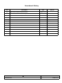
Abbreviations and Acronyms
API
ASIC
BIT
BIST
BIU
BMU
BSP
CLS
DAS
DMA
FDDI
FORMAC
FPROM
HCC
HPI
IRQ
LED
MAC
Mbit/s
MDR
MWI
OBS
PCI
PDR
PDT
PLC
PLC-S
PMC
PROM
RAM
VME
Application Program Interface
Application Specific Integrated Circuit
Built-in Test
Built-in Self Test
Bus Interface Unit
Buffer Management Unit
Board Support Package
Cache Line Size
Dual Attached Station
Direct Memory Access
Fibre Distributed Data Interface
Fibre Optic Ring Media Access Controller
Flash Programmable Read-only Memory
Host Carrier Card
Host Processor Interface
Interrupt Request
Light Emitting Diode
Media Access Control
Megabits per Second
Memory Data Register
Memory Write and Invalidate
Optical Bypass Switch
Peripheral Component Interconnect
Physical Data Receiver
Physical Data Transmitter
Physical Layer Controller
Physical Layer Controller with Scrambler
Peripheral Component Interconnect Mezzanine Card
Programmable Read-only Memory
Random Access Memory
Versa Module Eurocard
CCII/FDDI/6-MAN/003
CFDMAN03.WPD
2009-08-20
Issue 1.2
Page vi of vi
1.
Scope
1.1
Identification
This document is the user manual for the C²I² Systems Fibre Distributed Data Interface (FDDI) Adapter
VxWorks Built-in Test (BIT) Application.
1.2
System Overview
The FDDI VxWorks BIT Application was developed specifically to be ported to operate on a variety of Host
Carrier Cards (HCCs)1. As such the FDDI VxWorks BIT Application binaries are provided with explicit
installation instructions. The FDDI VxWorks BIT Application tests the low-level integrity of the FDDI hardware.
The FDDI adapters attach computers to 100 Mbit/s FDDI networks using fibre optic cable.
The BIT Application consists of the following files :
ccFdBit.a
ccFdBit.h
ccFddiX.o
BitDemo.c
Release.txt
1
FDDI BIT object file.
Header file for user applications.
Stub to allow BIT Application to be linked into kernel without FDDI driver.
Sample BIT Application.
Release notes and revision history: Please check this file for information on the latest updates.
Currently supports Dy4 SVME178, Radstone PPC, Power 4B and MVME 5100.
CCII/FDDI/6-MAN/003
CFDMAN03.WPD
2009-08-20
Issue 1.2
Page 1 of 20
2.
Applicable and Reference Documents
2.1
Applicable Documents
2.1.1
DI-IPSC-81443, Data Item Description for a Software User Manual.
2.1.2
CCII/FDDI/6-MAN/008, Installation Guide for the FDDI Adapter.
2.1.3
VxWorks 5.3.1 Programmer’s Guide, edition 1.
2.2
Reference Documents
None.
CCII/FDDI/6-MAN/003
CFDMAN03.WPD
2009-08-20
Issue 1.2
Page 2 of 20
3.
Installation Procedure
This paragraph describes the installation instructions for the FDDI VxWorks BIT Application.
3.1
To Build the BIT Application into the VxWorks Kernel
1.
Copy ccFddiX.o and ccFdBit.a to your Berkley Sockets Devices (BSP) library directory
(/tornado/target/config/svme178/lib).
2.
Edit the Makefile in the BSP directory (/tornado/target/config/svme178).
Find the line
MACH_EXTRA =
and replace with
MACH_EXTRA = ./lib/ccFddiX.o ./lib/ccFdBit.a
3.
3.2
Rebuild all VxWorks images.
To Build the FDDI Software Driver and BIT Application into the VxWorks Kernel
1.
Copy ccFdBit.a to your BSP library directory (/tornado/target/config/svme178/lib).
2.
Copy ccFddi.a (from your driver
(/tornado/target/config/svme178/lib).
3.
Edit the Makefile in the BSP directory (/tornado/target/config/svme178).
distribution)
to
your
BSP
library
directory
Find the line
MACH_EXTRA =
and replace with
MACH_EXTRA = ./lib/ccFddi.a ./lib/ccFdBit.a
4.
Add the following code fragment to config.h.
(before "#define DEFAULT_BOOT_LINE") :
#define INCLUDE_FDDI
#ifdef INCLUDE_FDDI
#define NETIF_USR_DECL IMPORT int ccfddiattach ();
#define NETIF_USR_ENTRIES \
{
"fddi", \
ccfddiattach, \
/* Unit = */ 0, \
/* Receive buffers = */ 0 /* = use default */, \
/* Transmit buffers = */ 0 /* = use default */ \
},
#endif /* INCLUDE_FDDI */
5.
3.3
Rebuild all VxWorks images.
To Load the BIT Application Separately
From the VxWorks shell, type :
ld < ccFdBit.a
The BIT Application may be operated without the FDDI Software Driver installed. Depending on the release
version in use, the following message might be displayed on loading the BIT Application :
CCII/FDDI/6-MAN/003
CFDMAN03.WPD
2009-08-20
Issue 1.2
Page 3 of 20
Undefined symbols:
ccfddiResumeDriver
ccfddiSuspendDriver
Warning: object module may not be usable because of undefined symbols.
This is normal and will not affect operation of the software.
3.4
Platform Specific Variations
This manual assumes that the executable is named ccFdBit.a. In order to prevent confusion, platform specific
variations are released with a unique filename, as listed below. The user should simply rename this file to ccFdBit.a
before using it, although the platform specific filename may be used as is, if desired. This manual however, refers
to the file as ccFdBit.a.
Dy4 178
RAD PPC
POWER 4B
MVME5100
ccFdBitSVME178vxxxx.a
ccFdBitRadPPCvxxxx.a
ccFdBitP4Bvxxxx.a
ccFdBitMVME5100vxxxx.a
Where xxxx represents the current version number of the release.
CCII/FDDI/6-MAN/003
CFDMAN03.WPD
2009-08-20
Issue 1.2
Page 4 of 20
4.
Application Program Interface (API)
All function prototypes, data types and structures described in this section are defined in the header file
ccFdBit.h.
4.1
BIT Functions
4.1.1
int ccfddiInitBIT (cc_test_message_style_type init_messages_style)
This function is used to initialise the BIT Application. The argument specifies the amount of text displayed during
initialisation of the BIT Application.
The function returns TRUE if initialisation is unsuccessful.
4.1.2
int ccfddiPOST (cc_tests_type *post_tests, cc_tests_report_type *post_results)
This function is used to initialise the BIT Application and run a set of startup tests.
If post_tests is NULL, a default set of tests appropriate to startup will be executed (i.e. no loopback or Light
Emitting Diode (LED) tests). The structure that defines this is called cc_default_post_tests.
If post_results is NULL, results will be written to the location cc_default_post_results.
The function returns TRUE if any of the tests return an error.
4.1.3
int ccfddiTest (cc_tests_type *tests, cc_tests_report_type *results)
This function runs a set of tests as specified in tests and places the results in results.
The function returns TRUE if any of the tests return an error.
4.1.4
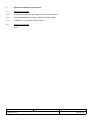
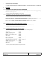
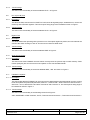
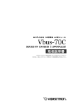
int ccfddiShowTestResults (cc_tests_report_type *results)
This function displays the test results in results as shown in the following example :
PROM Check
Timer and Hardware IRQ
FORMAC Register Check
RAM Check over MDR
RAM Check over DMA Engine
Memory Data Transfer Rate
PLC 1 Test
PLC 2 Test
Bypass Test
Wrap Around Check
FORMAC Loopback Check
Send and Receive Long Frames
Send and Master Access Loop
FORMAC Ring-Op Status
Configuration Registers Check
Special Card Check
ASIC Check
LED Test
PASSED
PASSED
PASSED
PASSED
PASSED
PASSED
PASSED
FAILED (Code 550)
SKIPPED
PASSED
FAILED (Code 191)
PASSED
FAILED (Code 191)
PASSED
PASSED
PASSED
PASSED
PASSED
The function returns TRUE if any of the tests reported a failure.
CCII/FDDI/6-MAN/003
CFDMAN03.WPD
2009-08-20
Issue 1.2
Page 5 of 20
4.2
BIT Data Types
4.2.1
cc_test_message_style_type
typedef enum {cc_quiet = 0,
cc_dots = 1,
cc_detailed = 2}
cc_test_message_style_type;
This type is used in the cc_test_option_type structure to control the amount of text displayed during execution
of a particular test.
The cc_quiet option is used when no output is desired.
The cc_dots option prints a series of dots to indicate test progress.
The cc_detailed option displays information which may be helpful in diagnosing faults.
4.2.2
cc_run_status_type
typedef enum {cc_skipped = 0,
cc_failed = 1,
cc_passed = 2}
cc_run_status_type;
This type is used in the cc_test_result_type structure to indicate the outcome of a particular test.
4.3
BIT Data Structures
4.3.1
cc_test_option_type
typedef struct
{
int do_test;
/* Set this to run test,
* otherwise test is skipped */
int stop_on_error;
/* If this is set, no more tests
* will be run if there
* is an fail */
int loop_forever;
/* Tests with this bit set will
* be run continuously */
cc_test_message_style_type test_message_style;
/* Determines appearance of test
* messages */
}
cc_test_option_type;
This structure controls the execution of a particular test.
If the do_test flag is set to TRUE, the test executed, otherwise it is skipped.
If the stop_on_error flag is set to TRUE for a test, and the test returns an error, then testing terminates
immediately (no further tests are run).
If the loop_forever flag is set to TRUE for any test, then testing continues indefinitely (i.e. all tests with this flag
set will be repeated continually). The stop_on_error flag would normally be used in conjunction with this. To
abort continuous testing, use the Control-C interrupt mechanism. If the driver was suspended for testing, then use
ccfddiResumeDriver to resume normal driver operation.
The cc_test_message_style determines how much output is displayed to the screen as described in
paragraph 4.2.1.
CCII/FDDI/6-MAN/003
CFDMAN03.WPD
2009-08-20
Issue 1.2
Page 6 of 20
4.3.2
cc_test_result_type
typedef struct
{
cc_run_status_type run_status;
int
result_code;
}
cc_test_result_type;
This structure captures the outcome of a particular test.
Test result codes are listed in Section 6.
4.3.3
cc_tests_type
typedef struct
{
int
cc_test_message_style_type
cc_test_option_type
cc_test_option_type
cc_test_option_type
cc_test_option_type
cc_test_option_type
cc_test_option_type
cc_test_option_type
cc_test_option_type
cc_test_option_type
cc_test_option_type
cc_test_option_type
cc_test_option_type
cc_test_option_type
cc_test_option_type
cc_test_option_type
cc_test_option_type
cc_test_option_type
cc_test_option_type
}
cc_tests_type;
loopback_mode;
init_messages_style;
prom_check;
timer_and_hardware_irq;
formac_register;
ram_check_over_mdr;
ram_over_dma_engine;
memory_data_transfer_rate;
plc_1_test;
plc_2_test;
bypass_test;
wrap_around_check;
formac_loopback;
send_and_receive_long_frames;
send_and_master_access_loop;
formac_ring_op_status;
configuration_registers_check;
special_card_check;
asic_check;
led_test;
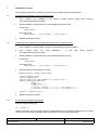
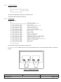
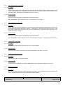
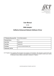
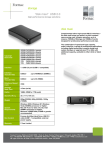
This structure controls the execution of all the tests.
If loopback_mode is TRUE, then the user must install wrap plugs on both ports before testing, as shown in
Figure 1 :
Figure 1 : Loopback Wrap Plugs
CCII/FDDI/6-MAN/003
CFDMAN03.WPD
2009-08-20
Issue 1.2
Page 7 of 20
The loopback_mode flag affects the following tests :
1.
2.
3.
4.
5.
PLC 1 Test
PLC 2 Test
FORMAC Loopback
Send and Receive Long Frames
Send and Master Access Loop
The init_messages_style member specifies the amount of text displayed during initialisation of the
BIT Application when calling ccfddiPOST.
cc_tests_report_type
typedef struct
{
cc_test_result_type
cc_test_result_type
cc_test_result_type
cc_test_result_type
cc_test_result_type
cc_test_result_type
cc_test_result_type
cc_test_result_type
cc_test_result_type
cc_test_result_type
cc_test_result_type
cc_test_result_type
cc_test_result_type
cc_test_result_type
cc_test_result_type
cc_test_result_type
cc_test_result_type
cc_test_result_type
}
cc_tests_report_type;
prom_check;
timer_and_hardware_irq;
formac_register;
ram_check_over_mdr;
ram_over_dma_engine;
memory_data_transfer_rate;
plc_1_test;
plc_2_test;
bypass_test;
wrap_around_check;
formac_loopback;
send_and_receive_long_frames;
send_and_master_access_loop;
formac_ring_op_status;
configuration_registers_check;
special_card_check;
asic_check;
led_test;
This structure captures the outcome of all tests.
4.3.4
Application Example
The following source file is a simple demonstration of how to execute the BIT functions :
#include "ccFdBit.h"
cc_tests_type tests =
{FALSE, /* Loopback NOT connected */
cc_detailed,
/* {do_test, stop_on_error, loop_forever, test_message_style} */
{TRUE, FALSE, FALSE, cc_detailed}, /* prom_check */
{TRUE, FALSE, FALSE, cc_detailed}, /* timer_and_hardware_irq */
{TRUE, FALSE, FALSE, cc_detailed}, /* formac_register */
{TRUE, FALSE, FALSE, cc_detailed}, /* ram_check_over_mdr */
{TRUE, FALSE, FALSE, cc_detailed}, /* ram_over_dma_engine */
{TRUE, FALSE, FALSE, cc_detailed}, /* memory_data_transfer_rate */
{TRUE, FALSE, FALSE, cc_dots},
/* plc_1_test */
{TRUE, FALSE, FALSE, cc_dots},
/* plc_2_test */
{FALSE, FALSE, FALSE, cc_detailed},/* bypass_test */
{TRUE, FALSE, FALSE, cc_detailed}, /* wrap_around_check */
{TRUE, FALSE, FALSE, cc_detailed}, /* formac_loopback */
{TRUE, FALSE, FALSE, cc_detailed}, /* send_and_receive_long_frames */
{TRUE, FALSE, FALSE, cc_detailed}, /* send_and_master_access_loop */
{TRUE, FALSE, FALSE, cc_detailed}, /* formac_ring-op_status */
{TRUE, FALSE, FALSE, cc_detailed}, /* configuration_registers_check */
{TRUE, FALSE, FALSE, cc_quiet},
/* special_card_check */
{TRUE, FALSE, FALSE, cc_quiet},
/* asic_check */
{TRUE, FALSE, FALSE, cc_quiet},
/* led_test */
};
cc_tests_report_type results;
int BitDemo (void)
CCII/FDDI/6-MAN/003
CFDMAN03.WPD
2009-08-20
Issue 1.2
Page 8 of 20
{
ccfddiInitBIT (cc_detailed);
ccfddiTest (&tests, &results);
return ccfddiShowTestResults (&results);
}
CCII/FDDI/6-MAN/003
CFDMAN03.WPD
2009-08-20
Issue 1.2
Page 9 of 20
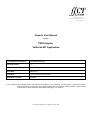
5.
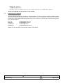
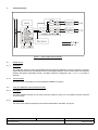
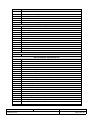
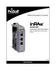
Test Descriptions
Figure 2 : FDDI Adapter Block Diagram
5.1
PROM Check
5.1.1
Description
This reads the contents of the Programmable Read-only Memory (PROM) to an array, and does a compare
against the first three bytes of the Media Access Control (MAC) address. This is done to make sure the MAC
address falls within reasonable bounds. The MAC address is displayed if the cc_detailed mode is
selected.
5.1.2
Test Coverage
This test covers functionality of the block labelled ‘FPROM’ in Figure 2.
5.2
Timer and Hardware Interrupt Request (IRQ)
5.2.1
Description
This tests whether the timer can be used correctly, whether it times out, and whether the timer interrupt
occurs correctly.
5.2.2
Test Coverage
This test covers partial functionality of the blocks labelled ‘BIU’ and ‘MAC’ in Figure 2.
CCII/FDDI/6-MAN/003
CFDMAN03.WPD
2009-08-20
Issue 1.2
Page 10 of 20
5.3
FORMAC Register
5.3.1
Description
This checks the Fibre Optic Ring Media Access Controller (FORMAC) and programmable registers. The test
uses all read-only and read-write registers. It also tests the initialisation of counters and other registers. In
addition, it executes a test on the Address Filter Function of the SUPERNET 3 chipset.
5.3.2
Test Coverage
The test covers partial functionality of the blocks labelled ‘Control Register File’ and ‘MAC’ in Figure 2.
5.4
RAM Check Over MDR
5.4.1
Description
This reads from and writes to Random Access Memory (RAM) on the FDDI Adapter using the Memory Data
Register (MDR), and verifies the data.
5.4.2
Test Coverage
This test covers functionality of the block labelled ‘Buffer Memory’ in Figure 2.
5.5
Random Access Memory Over Direct Memory Access Engine
5.5.1
Description
This reads from and writes to RAM on the FDDI Adapter using Direct Memory Access (DMA) master
transfers.
5.5.2
Test Coverage
This test covers functionality of the block labelled ‘Buffer Memory’ in Figure 2.
5.6
Memory Data Transfer Rate
5.6.1
Description
This test measures raw master access speed, and prints the values to the console. The speed is measured
with differing Cache Line Size (CLS), byte aligned or misaligned, and in different Memory Write and
Invalidate (MWI) modes.
5.6.2
Test Coverage
Although not strictly a test, this will exercise functionality of the Bus Interface Unit (BIU) and Host Processor
Interfaces (HPI) of the Application Specific Integrated Circuit (ASIC).
5.7
PLC 1 (Port A) Test
5.7.1
Description
This tests the IRQ, executes the Physical Layer Controller (PLC) Built-in Self Test (BIST) for Port A, does
bit signalling loops, initialises timer, checks the read-only and read-write registers. This test requires wrap
plugs to be installed as shown in Figure 1.
CCII/FDDI/6-MAN/003
CFDMAN03.WPD
2009-08-20
Issue 1.2
Page 11 of 20
5.7.2
Test Coverage
This test covers functionality of the block labelled ‘PLC 1’ in Figure 2.
5.8
PLC 2 (Port B) Test
5.8.1
Description
This tests the IRQ, executes the PLC BIST for Port B, does bit signalling loops, initialises timer, checks the
read-only and read-write registers. This test requires wrap plugs to be installed as shown in Figure 1.
5.8.2
Test Coverage
This test covers functionality of the block labelled ‘PLC 2’ in Figure 2.
5.9
Bypass Test
5.9.1
Description
This tests whether the optical bypass is present or not. If the optical bypass is present, the user will hear the
sound of the switch clicking on and off. This test never returns a failed result.
5.9.2
Test Coverage
This test covers functionality of the block labelled ‘OBS’ in Figure 2.
5.10
Wrap Around Check
5.10.1 Description
This test checks if the FORMAC receives frames correctly when the queues wrap in buffer memory. Short
frames (20 Bytes) are sent and received in loopback. It also checks DMA transfer.
5.10.2 Test Coverage
This test covers functionality of the blocks labelled ‘BMU’, ‘BIU’ and ‘MAC’ in Figure 2.
5.11
FORMAC Loopback
5.11.1 Description
This test verifies that the FORMAC can send and receive data without using DMA master access. Various
levels of loopback are performed (after MAC, after PLC 1, after PDT/R 1, after Transceiver and Connector 1,
after PLC 1 and 2, after PDT/R 2 and after Transceiver and Connector 2. This test requires wrap plugs to
be installed as shown in Figure 1.
5.11.2 Test Coverage
This test covers functionality of the following blocks from Figure 2 :
ASIC, SUPERNET 3 FDDI Controller, PLC-S, Transceiver and Connector 1, Transceiver and Connector 2.
CCII/FDDI/6-MAN/003
CFDMAN03.WPD
2009-08-20
Issue 1.2
Page 12 of 20
5.12
Send and Receive Long Frames
5.12.1 Description
This test sends and receives long frames using the synchronous and asynchronous transmit queues. Long
frames (various lengths up to 4 400 Bytes) are sent and received in loopback. DMA transfer is tested as well.
This test requires wrap plugs to be installed as shown in Figure 1.
5.12.2 Test Coverage
This test covers functionality of the following blocks from Figure 2 :
ASIC, SUPERNET 3 FDDI Controller, PLC-S, Transceiver and Connector 1.
5.13
Send and Master Access Loop
5.13.1 Description
This test shall prove that the FORMAC can send and receive data using DMA master access. Various levels
of loopback are performed (after MAC, after PLC 1, after PDT/R 1, after Transceiver and Connector 1, after
PLC 1 and 2, after PDT/R 2 and after Transceiver and Connector 2. This test requires wrap plugs to be
installed as shown in Figure 1.
5.13.2 Test Coverage
This test covers functionality of the following blocks from Figure 2 :
ASIC, SUPERNET 3 FDDI Controller, PLC-S, Transceiver and Connector 1, Transceiver and Connector 2.
5.14
FORMAC Ring-Op Status
5.14.1 Description
This test checks that the Ring-Op interrupt occurs in the FORMAC.
5.14.2 Test Coverage
This test covers partial functionality of the blocks labelled ‘BIU’ and ‘MAC’ in Figure 2.
5.15
Configuration Registers Check
5.15.1 Description
This test checks the configuration registers.
5.15.2 Test Coverage
This test covers functionality of the blocks labelled ‘BIU’ and ‘Configuration Registers’ in Figure 2.
5.16
Special Card Check
5.16.1 Description
This runs the parity mode tests, checks all timers in test mode, checks whether writes can be made to I/O
space, tests descriptor bits and checks the Bank 0 special registers.
CCII/FDDI/6-MAN/003
CFDMAN03.WPD
2009-08-20
Issue 1.2
Page 13 of 20
5.16.2 Test Coverage
This test covers functionality of the blocks labelled ‘BIU’, ‘BMU’, ‘HPI’ and part of ‘MAC’ in Figure 2.
5.17
ASIC Check
5.17.1 Description
This checks ASIC functions, as well as the DMA engine with all possible alignments.
5.17.2 Test Coverage
This test covers functionality of the blocks labelled ‘BIU’, ‘BMU’, ‘HPI’ and ‘Buffer Memory’ in Figure 2.
5.18
LED Test
5.18.1 Description
The three adapter LEDs are turned on in all eight combinations, for one second each. The user must verify
that these display correctly. This test never returns a failed result.
5.18.2 Test Coverage
This test covers functionality of the blocks labelled ‘BIU’ and ‘LEDs’ in Figure 2.
CCII/FDDI/6-MAN/003
CFDMAN03.WPD
2009-08-20
Issue 1.2
Page 14 of 20
6.
Test Result Codes
Code
150
160
161
162
163
164
165
166
167
169
170
171
172
173
174
175
176
177
178
179
180
181
182
183
184
185
186
187
188
189
190
D191
D191
192
193
199
200
Description
dma_read_check()
Mapped POS_106 register defective
LED register
Cannot switch LED 2 (DAS) on
Cannot switch LED 2 (DAS) off
Mapped POS_103 register defective (0x36, FM1)
Mapped POS_100 register defective
Mapped POS_101 register defective
Mapped POS_102 register defective
Mapped POS_104 register defective
Mapped POS_103 register defective (0x2e)
CSR_A defective (adapter disabled)
CSR_A defective (adapter enabled)
CSR_A defective (fifo reset)
CSR_A defective (fifo enable)
CSR_A defective (IRQ other enabled)
CSR_A defective (IRQ other disabled)
CSR_A defective (IRQ check enabled)
CSR_A defective (IRQ check disabled)
CSR_A defective (IRQ RTM enabled)
CSR_A defective (IRQ RTM disabled)
CSR_A defective (IRQ Terminal count enabled)
CSR_A defective (IRQ Terminal count disabled)
Cannot switch LED_0 on and LED_1 off
Cannot switch LED_0 off and LED_1 on
Cannot switch LED_0 off and LED_1 off
Cannot switch LED 2 (DAS) on
Cannot switch LED 2 (DAS) off
Cannot switch to bypass station (DAS)
Cannot switch to insert station (DAS)
Host request register defective : value cannot be read
MAC does not go to Ring-Op
Host request register defective : should be in read request
Host request register defective : should not be in read request
Page register defective
Timeout ("timer data path\n",1)
FORMAC+ Register Tests
FM_IMSK1U
201
202
203
204
205
206
FM_IMSK1L
FM_IMSK2U
FM_IMSK2L
FM_SAID
FM_LAIM
FM_LAIC
CCII/FDDI/6-MAN/003
CFDMAN03.WPD
2009-08-20
Issue 1.2
Page 15 of 20
Code
207
208
209
210
211
220
221
222
224
225
226
227
228
229
230
231
232
233
234
235
236
237
238
239
240
241
242
243
244
245
246
247
248
249
250
251
254
255
256
Description
FM_LAIL
FM_SAGP
FM_LAGM
FM_LAGC
FM_LAGL
FM_PRI1
FM_PRI2
FM_TSYNC
FM_FRMTHR
FM_EACB
FM_EARV
FM_EAS
FM_EAA0
FM_EAA1
FM_EAA2
FM_SACL
FM_SABC
FM_WPXSF
FM_RPXSF
FM_RPR
FM_WPR
FM_SWPR
FM_WPXS
FM_WPXA0
FM_WPXA1
FM_WPXA2
FM_SWPXS
FM_SWPXA0
FM_SWPXA1
FM_SWPXA2
FM_RPXS
FM_RPXA0
FM_RPXA1
FM_RPXA2
FM_MARR
FM_MARW
FM_FCNTR
FM_LCNTR
FM_ECNTR
FORMAC+ Register Tests (Initial Values)
261
262
263
264
265
268
FM_MIR1
FM_MIR0
FM_PRI0
FM_PRI1
FM_PRI2 (SN2)
FM_TNEG
CCII/FDDI/6-MAN/003
CFDMAN03.WPD
2009-08-20
Issue 1.2
Page 16 of 20
Code
269
270
271
272
273
274
274
274
274
274
274
274
274
274
274
274
274
274
274
274
274
274
274
274
274
274
274
274
274
274
274
274
274
274
274
274
280
281
282
283
284
285
286
302
303
Description
FM_TSYNC
FM_FCNTR
FM_ECNTR
FM_LCNTR
FM_TMAX
FM_THT
FM_TVX
FM_TMSYNC (SN3)
FM_ST1U (SN3)
FM_ST1L (SN3)
FM_ST2U (SN3)
FM_ST2L (SN3)
FM_ST3U (SN3)
FM_ST3L (SN3)
FM_IMSK1U (SN3)
FM_IMSK1L (SN3)
FM_IMSK2U (SN3)
FM_IMSK2L (SN3)
FM_IMSK3U (SN3)
FM_IMSK3L (SN3)
FM_IVR (SN3)
FM_IMR (SN3)
FM_SAID (SN3)
FM_LAIM (SN3)
FM_LAIC (SN3)
FM_LAIL (SN3)
FM_SAGP (SN3)
FM_LAGM (SN3)
FM_LAGC (SN3)
FM_LAGL (SN3)
FM_MDREG1 (SN3)
FM_MDREG2 (SN3)
FM_MDREG3 (SN3)
FM_STMCHN (SN3)
FM_FSCNTR (SN3)
FM_FRMTHR (SN3)
Address Filter Test (IFCP / SUPERNET 3 only)
IFCP_3 Interrupt already set
Status register not cleared
AF Built-in Self Test timeout!
IRQ occured but AF_BIST_DONE (ST3) not set
IRQ occured but BIST_DONE (AFSTAT) not set
IRQ occured but DONE not set
AF BIST signature wrong
PROM : wrong MAC address (man-code or IBM 4. Byte)
Error on board RAM (RBC)
CCII/FDDI/6-MAN/003
CFDMAN03.WPD
2009-08-20
Issue 1.2
Page 17 of 20
Code
304
307
310
350
355
392
400
401
402
403
404
405
406
407
408
409
410
411
412
420
450
451
452
453
550
608
609
612
651
652
653
654
655
656
657
658
659
660
661
662
663
670
671
Description
PROM : error in LOGO
Error on board RAM (RBC)
Flash : Protection violation
Write MDR ???
PCM_CODE does not set
Error on board RAM (RBC)
PLC : Register Errors
PL_CNTRL_A
PL_CNTRL_B
PL_INTR_MASK
PL_XMIT_VECTOR
PL_VECTOR_LEN
PL_LE_THRESHOLD
PL_C_MIN
PL_TL_MIN
PL_TB_MIN
PL_T_OUT
PL_LC_LENGTH
PL_T_SCRUB
PL_NS_MAX
PLC : Other Errors
Scrambler needed but not present
Special Hardware Dependent Errors
Counter Test error
VPD error
Reset Test error
Watchdog error
bit_sign() PL_RCV_VECTOR
Compare error during DMA read
Compare error during DMA write
PCI : Timeout EOB not signaled
PCI : FORMAC parity check failure during send
PCI : FORMAC parity generation failure during receive
PCI : Parity status already set
PCI : PCI Parity error
PCI : mem_mapped test error
PCI : test_mode test error
PCI : BMU BIT test error
PCI : CFG space writes via IO space
PCI : Error in Bank 0 test
PCI : Error in CTRL register tests
PCI : DMA single test: cannot complete DMA
PCI : Error in Power Management Capability tests
PCI : diag_bmu, Descriptor is not given back
PCI : VPD transfer does not complete
PCI : VPD write error
CCII/FDDI/6-MAN/003
CFDMAN03.WPD
2009-08-20
Issue 1.2
Page 18 of 20
Code
672
673
674
675
676
677
801
802
803
804
805
810
899
900
901
902
903
904
905
906
907
908
909
910
998
999
Description
PCI : Voltage sensor value out of the limits
PCI : Voltage sensor defective
PCI : Temperature sensor value out of the limits
PCI : Temperature sensor defective
PCI : I²C transfer does not complete
PCI : FPROM VPD ROM size does not match I²C EEPROM size
Check Timer 82C54
Timer 82C54 does not decrement
Timer IRQ does not occur
IRQ is pending
Hardware Timer IRQ does not occur
Timer clock was not correct
(check token status)
PCI : STF or EOF not set in loopback test
PCI : MSVALID is not set in loopback test
PCI : Memory status receive abort in loopback test
PCI : Received frame not valid in loopback test
PCI : E-Indicator set in loopback test
PCI : FORMAC rx len unequal descriptor len in loopback test
PCI : length error in loopback test
PCI : Wrong FC found in loopback test
PCI : C-Indicator set in loopback test
PCI : Cannot get dummy RxD in loopback test
PCI : Stop Master test failed during loopback test
PCI : Token Counter does not increment in loopback test
Data header or body defective in loopback test
Illegal size in loopback test
CCII/FDDI/6-MAN/003
CFDMAN03.WPD
2009-08-20
Issue 1.2
Page 19 of 20
7.
Contact Details
7.1
Contact Person
Direct all correspondence and / or support queries to the Project Manager at C²I² Systems.
7.2
Physical Address
C²I² Systems
Unit 3, Rosmead Place, Rosmead Centre
67 Rosmead Avenue
Kenilworth
Cape Town
7708
South Africa
7.3
Postal Address
C²I² Systems
P.O. Box 171
Rondebosch
7701
South Africa
7.4
Voice and Electronic Contacts
Tel
Fax
Email
Email
URL
7.5
:
:
:
:
:
(+27) (0)21 683 5490
(+27) (0)21 683 5435
[email protected]
[email protected]
http://www.ccii.co.za/
Product Support
Support on C²I² Systems products is available telephonically between Monday and Friday from 09:00 to
17:00 CAT. Central African Time (CAT = GMT + 2).
CCII/FDDI/6-MAN/003
CFDMAN03.WPD
2009-08-20
Issue 1.2
Page 20 of 20