1
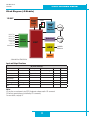
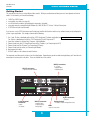
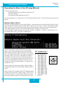
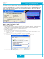
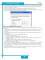
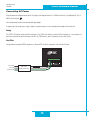
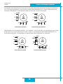
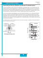
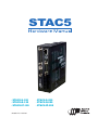
STAC5
• STAC5-S-120
• STAC5-Q-120
• STAC5-IP-120
920-0026 Rev. B 4/22/2011
• STAC5-S-220
• STAC5-Q-220
• STAC5-IP-220
920-0026 Rev. B
4/22/2011
STAC5 Hardware manual
Contents
Introduction................................................................................................................................................................................................ 3
Features...................................................................................................................................................................................................... 3
List of STAC5 Model Numbers.................................................................................................................................................................... 3
Block Diagram (-S Models)........................................................................................................................................................................ 4
Block Diagram (-Q and -IP Models)............................................................................................................................................................ 5
Getting Started............................................................................................................................................................................................ 6
Connecting the Drive to Your PC using Ethernet......................................................................................................................................... 7
Addresses, Subnets, and Ports.............................................................................................................................................................. 7
Option 1: Connect a Drive to Your Local Area Network......................................................................................................................... 8
Option 2: Connect a Drive Directly to Your PC................................................................................................................................... 10
Option 3: Use Two Network Interface Cards (NICs)............................................................................................................................ 11
Connecting AC Power............................................................................................................................................................................... 12
Fusing................................................................................................................................................................................................. 12
Line Filter............................................................................................................................................................................................ 12
Connecting the Motor............................................................................................................................................................................... 13
Connecting Other Motors.......................................................................................................................................................................... 13
Connecting an Encoder (Requires the Encoder Feedback option)............................................................................................................. 15
IO Functions (-S model)........................................................................................................................................................................... 16
IO Functions (-Q and -IP models)............................................................................................................................................................. 17
Connecting Input Signals.......................................................................................................................................................................... 18
Connector Pin Diagrams.........................................................................................................................................................................
High Speed Digital Inputs................................................................................................................................................................... 19
Lower Speed, Differential Digital Inputs.............................................................................................................................................. 20
Single Ended Digital Inputs................................................................................................................................................................. 22
What is COM? ................................................................................................................................................................................... 22
Analog Input............................................................................................................................................................................................. 23
Connecting a Potentiometer to the Analog Input................................................................................................................................. 23
Programmable Outputs............................................................................................................................................................................. 24
Sinking Output Using OUT1, OUT2 or OUT3....................................................................................................................................... 24
Sinking Output Using Y1, Y2 or OUT4................................................................................................................................................ 24
Sourcing Output Using OUT1, OUT2 or OUT3.................................................................................................................................... 25
Sourcing Output Using Y1, Y2 or OUT4.............................................................................................................................................. 25
Driving a Relay OUT1, OUT2 or OUT3................................................................................................................................................. 25
Driving a Relay Using Y1, Y2, or OUT4............................................................................................................................................... 25
Recommended Motors (120V Models)..................................................................................................................................................... 26
Recommended Motors (220V Models)..................................................................................................................................................... 26
Torque-Speed Curves............................................................................................................................................................................... 27
Motor Heating........................................................................................................................................................................................... 29
Drive Heating............................................................................................................................................................................................ 30
Mounting the Drive................................................................................................................................................................................... 31
Mechanical Outline................................................................................................................................................................................... 31
Technical Specifications............................................................................................................................................................................ 32
Mating Connectors and Accessories......................................................................................................................................................... 33
Alarm Codes............................................................................................................................................................................................. 34
Connector Diagrams................................................................................................................................................................................. 34
2
920-0026 Rev. B
4/22/2011
STAC5 Hardware manual
Introduction
Thank you for selecting an Applied Motion Products motor control. We hope our dedication to performance, quality and economy will
make your motion control project successful.
If there’s anything we can do to improve our products or help you use them better, please call or fax. We’d like to hear from you. Our
phone number is (800) 525-1609, or you can reach us by fax at (831) 761-6544. You can also email [email protected].
Features
•
•
•
•
•
•
•
•
•
•
•
•
•
Programmable, microstepping digital step motor driver in compact package
STAC5-120 models operate from 120VAC
STAC5-220 operates from 220VAC
Ethernet 100 MBit communication
Optional Ethernet/IP protocol communication
Operates in velocity or position mode
Accepts analog signals, digital signals, and Ethernet commands
Optional encoder feedback
STAC5-120 provides motor current up to 5 amps/phase (peak of sine)
STAC5-220 provides motor current up to 2.55 amps/phase (peak of sine)
-S: four optically isolated digital inputs, two optically isolated digital outputs
-Q, -IP: twelve optically isolated digital inputs, six optically isolated digital outputs
±10 volt analog input for speed and position control. Can also be configured for 0 to 10V, ±5V or 0 to 5V signal ranges.
List of STAC5 Model Numbers
STAC5-S-N120
STAC5-S-E120
STAC5-S-N220
STAC5-S-E220
STAC5-Q-N120
STAC5-Q-E120
STAC5-Q-N220
STAC5-Q-E220
STAC5-IP-N120
STAC5-IP-E120
STAC5-IP-N220
STAC5-IP-E220
An “E” in the model number indicates the inclusion of the optional Encoder Feedback connector.
An “N” in the model number indicates no encoder feedback connector on the drive.
3
920-0026 Rev. B
4/22/2011
STAC5 Hardware manual
Block Diagram (-S Models)
120 VAC*
INPUT X1
INPUT X2
INPUT X3
INPUT X4
OUT Y1
OUT Y2
ANALOG IN
Internal
Logic
Supply
Optical
Isolation
Status
MOSFET
PWM
Power
Amplifier
motor
Option Card
encoder
ARM
100MBit
Ethernet
DSP
eeprom
*220 VAC for STAC5-220
Input and Output Functions
X1
Step
CW Pulse
A Quadrature
Run/Stop
CW Limit
CW Jog
GP
X2
Direction
CCW Pulse
B Quadrature
IN/OUT1 Connector
X3
X4
Alarm Reset
Speed Change
Enable Motor GP
GP
Y1
Fault
GP
CCW Limit
CCW Jog
GP
Notes
I/O functions are configured using STAC Configurator software and/or SCL commands.
GP indicates general purpose (controlled by SCL commands)
For more details, see page 12
4
Y2
Brake
Motion
Tach
GP
920-0026 Rev. B
4/22/2011
STAC5 Hardware manual
Block Diagram (-Q and -IP Models)
120 VAC*
Internal
Logic
Supply
INPUT X1
INPUT X2
INPUT X3
INPUT X4
INPUT 1
INPUT 2
INPUT 3
INPUT 4
INPUT 5
INPUT 6
INPUT 7/CWLIM
INPUT 8/CCWLIM
OUT Y1
OUT Y2
OUT 1
OUT 2
OUT 3
OUT 4
ANALOG IN
Optical
Isolation
Status
MOSFET
PWM
Power
Amplifier
motor
Option Card
encoder
ARM
100MBit
Ethernet
DSP
eeprom
*220 VAC for -220 models
Input and Output Functions
X1
Step
A Quadrature
CW Pulse
Run/Stop
GP
X2
Direction
B Quadrature
CCW Pulse
Y1
Fault
GP
Y2
Brake
Tach
GP
GP
IN1
IN2
CW Jog CCW Jog
IN/OUT1 Connector
X3
X4
Alarm Reset
Speed Change
Enable Motor GP
GP
IN3
GP
IN/OUT2 Connector (OPT2)
IN4 IN5 IN6 IN7
IN8
OUT1
OUT2 OUT3
GP GP GP CW Limit CCW Limit Motion GP
GP
GP
GP
GP
Notes
I/O functions are configured using STAC Configurator software and/or SCL & Q commands.
GP indicates general purpose (controlled by SCL or Q commands)
For more details, see page 13
5
OUT4
GP
920-0026 Rev. B
4/22/2011
STAC5 Hardware manual
Getting Started
This manual describes the use of four different drive models. What you need to know and what you must have depends on the drive
model. For all models, you’ll need the following:
•
•
•
•
•
120VAC or 220VAC power.
a compatible step motor (see page 25)
a small flat blade screwdriver for tightening the connectors (included).
a personal computer running Microsoft Windows 98, 2000, NT, Me, XP, Vista or 7 with an Ethernet port.
A CAT5 Ethernet cable (not included).
If you’ve never used a STAC5 drive before you’ll need to get familiar with the drive and the set up software before you try to deploy the
system in your application. We strongly recommend the following:
1.
2.
3.
4.
5.
6.
7.
For -S and -IP drives, download and install the STAC Configurator™ software application from www.applied-motion.com/software.
For -Q drives, download and install the STAC Configurator™ and Q Programmer™ Launch the software by clicking Start...Programs...Applied Motion...
Connect the drive to your PC using Ethernet and set the IP address (see Connecting to the PC).
Connect the drive to the AC power (see Connecting AC Power).
Connect the drive to the motor (see Connecting the Motor).
Apply power to the drive.
Set the IP address of the software to match the drive.
The connectors and other points of interest are illustrated below. Depending on your drive model and application, you’ll need to make
connections to various parts of the drive. These are detailed later in the manual.
DB-25 connector
-Q , -IP only
• 8 digital inputs
• 4 digital outputs
345
BCD
screw terminal
connector
• motor
• AC power
DB-15 connector
• 4 digital inputs
• 2 digital outputs
• analog input
6
89A
EF
67
0 12
HD-15 connector
• optional encoder feedback
RJ45 connector
• Ethernet
Rotary Switch
• IP address and/or configuration select
LEDs
• status
& error codes
920-0026 Rev. B
4/22/2011
STAC5 Hardware manual
Connecting the Drive to Your PC using Ethernet
This process requires three steps
•
Physically connect the drive to your network (or directly to the PC)
•
Set the drive’s IP address
•
Set the appropriate networking properties on your PC.
Note: the following pages are an excerpt from the “eSCL Communication Reference Guide”. For more information, please read the rest of
the guide.
Addresses, Subnets, and Ports
Every device on an Ethernet network must have a unique IP address. In order for two devices to communicate with each other, they must
both be connected to the network and they must have IP addresses that are on the same subnet. A subnet is a logical division of a larger
network. Members of one subnet are generally not able to communicate with members of another unless they are connected through
special network equipment (e.g. router). Subnets are defined by the choices of IP addresses and subnet masks.
If you want to know the IP address and subnet mask of your PC, select Start…All Programs…Accessories…Command Prompt. Then
type “ipconfig” and press Enter. You should see something like this:
If your PC’s subnet mask is set to 255.255.255.0, a common setting
known as a Class C subnet mask, then your machine can only talk to
another network device whose IP address matches yours in the first three
octets. (The numbers between the dots in an IP address are called octets.)
For example, if your PC is on a Class C subnet and has an IP address
of 192.168.0.20, it can talk to a device at 192.168.0.40, but not one at
192.168.1.40. If you change your subnet mask to 255.255.0.0 (Class B)
you can talk to any device whose first two octets match yours. Be sure
to ask your system administrator before doing this. You network may be
segmented for a reason.
345
EF
89A
BCD
7
10.10.10.10
192.168.1.10
192.168.1.20
192.168.1.30
192.168.0.40
192.168.0.50
192.168.0.60
192.168.0.70
192.168.0.80
192.168.0.90
192.168.0.100
192.168.0.110
192.168.0.120
192.168.0.130
192.168.0.140
DHCP
67
0
1
2
3
4
5
6
7
Your drive includes a 16 position rotary switch for setting its IP address.
8
The factory default address for each switch setting is shown in the table to 9
the right.
A
B
Settings 1 through E can be changed using the STAC Configurator software C
(use Quick Tuner for servo drives). Setting 0 is always “10.10.10.10”, the
D
universal recovery address. If someone were to change the other settings
E
and not write it down or tell anyone (I’m not naming names here, but you
F
0 12
IP Address*
920-0026 Rev. B
4/22/2011
STAC5 Hardware manual
know who I’m talking about) then you will not be able to communicate with your drive. The only way to “recover” it is to use the universal
recovery address.
Setting F is “DHCP”, which commands the drive to get an IP address from a DHCP server on the network. The IP address automatically
assigned by the DHCP server may be “dynamic” or “static” depending on how the administrator has configured DHCP. The DHCP setting
is reserved for advanced users.
Your PC, or any other device that you use to communicate with the drive, will also have a unique address.
On the drive, switch settings 1 through E use the standard class B subnet mask (i.e. “255.255.0.0”). The mask for the universal recovery
address is the standard class A (i.e. “255.0.0.0”).
One of the great features of Ethernet is the ability for many applications to share the network at the same time. Ports are used to direct
traffic to the right application once it gets to the right IP address. The UDP eSCL port in our drives is 7775. To send and receive commands using TCP, use port number 7776. You’ll need to know this when you begin to write your own application. You will also need to
choose an open (unused) port number for your application. Our drive doesn’t care what that is; when the first command is sent to the
drive, the drive will make note of the IP address and port number from which it originated and direct any responses there. The drive will
also refuse any traffic from other IP addresses that is headed for the eSCL port. The first application to talk to a drive “owns” the drive.
This lock is only reset when the drive powers down.
If you need help choosing a port number for your application, you can find a list of commonly used port numbers at http://www.iana.org/
assignments/port-numbers.
One final note: Ethernet communication can use one or both of two “transport protocols”: UDP and TCP. eSCL commands can be sent
and received using either protocol. UDP is simpler and more efficient than TCP, but TCP is more reliable on large or very busy networks
where UDP packets might occasionally be dropped.
Option 1: Connect a Drive to Your Local Area Network
If you have a spare port on a switch or router and if you are able to set your drive to an IP address that is compatible with your network,
and not used by anything else, this is a simple way to get connected. This technique also allows you to connect multiple drives to your
PC. If you are on a corporate network, please check with your system administrator before connecting anything new to the network. He
or she should be able assign you a suitable address and help you get going.
NIC
LAN
SWITCH
or
ROUTER
PC
DRIVE
If you are not sure which addresses are already used on your network, you can find out using “Angry IP scanner”, which can be downloaded free from http://www.angryip.org/w/Download. But be careful: an address might appear to be unused because a computer or
other device is currently turned off. And many networks use dynamic addressing where a DHCP server assigns addresses “on demand”.
The address you choose for your drive might get assigned to something else by the DHCP server at another time.
Once you’ve chosen an appropriate IP address for your drive, set the rotary switch according the address table above. If none of the
8
920-0026 Rev. B
4/22/2011
STAC5 Hardware manual
default addresses are acceptable for your network, you can enter a new table of IP addresses using Configurator. If your network uses addresses starting with 192.168.0, the most common subnet, you will want to choose an address from switch settings 4 through E. Another
common subnet is 192.168.1. If your network uses addresses in this range, the compatible default selections are 1, 2 and 3.
If your PC address is not in one of the above private subnets, you will have to change your subnet mask to 255.255.0.0 in order to talk to
your drive. To change your subnet mask:
1. On Windows XP, right click on “My Network Places” and select properties. On Windows 7, click Computer. Scroll down the left
pane until you see “Network”. Right click and select properties. Select “Change adapter settings”
2. You should see an icon for your network interface card (NIC). Right click and select properties.
3. Scroll down until you see “Internet Properties (TCP/IP)”. Select this item and click the Properties button. On Windows 7 and Vista,
look for “(TCP/IPv4)”
4. If the option “Obtain an IP address automatically” is selected, your PC is getting an IP address and a subnet mask from the DHCP
server. Please cancel this dialog and proceed to the next section of this manual: “Using DHCP”.
5. If the option “Use the following IP address” is selected, life is good. Change the subnet mask to “255.255.0.0” and click OK.
Using DCHP
If you want to use your drive on a network that where all or most of the devices use dynamic IP addresses supplied by a DHCP server, set
the rotary switch to “F”. When the drive is connected to the network and powered on, it will obtain an IP address and a subnet mask from
the server that is compatible with your PC. The only catch is that you won’t know what address the server assigns to your drive. Ethernet
Configurator can find your drive using the
Drive Discovery feature, as long as your
network isn’t too large. With the drive connected to the network and powered on, select
Drive Discovery from the Drive menu.
You will see a dialog such as this:
Normally, Drive Discovery will only detect
one network interface card (NIC), and will
select it automatically. If you are using a
laptop and have both wireless and wired network connections, a second NIC may appear.
Please select the NIC that you use to connect
9
920-0026 Rev. B
4/22/2011
STAC5 Hardware manual
to the network to which you’ve connected your drive. Then click OK. Drive Discovery will notify you as soon as it has detected a drive.
If you think this is the correct drive, click Yes. If you’re not sure, click Not Sure and Drive Discovery will look for additional drives on you
network. Once you’ve told Drive Discovery which drive is yours, it will automatically enter that drive’s IP address in the IP address text
box so that you are ready to communicate.
Option 2: Connect a Drive Directly to Your PC
It doesn’t get much simpler than this:
1. Connect one end of a CAT5 Ethernet cable into the LAN card (NIC) on your PC and the other into the drive. You don’t need a special
“crossover cable”; the drive will automatically detect the direct connection and make the necessary physical layer changes.
2. Set the IP address on the drive to “10.10.10.10” by setting the rotary switch at “0”.
3. To set the IP address of your PC:
a. On Windows XP, right click on “My Network Places” and select properties.
b. On Windows 7, click Computer. Scroll down the left pane until you see “Network”. Right click and select properties. Select
“Change adapter settings”
4. You should see an icon for your network interface card (NIC). Right click and select properties.
a. Scroll down until you see “Internet Properties (TCP/IP)”. Select this item and click the Properties button.
b. On Windows 7 and Vista, look for “(TCP/IPv4)”
10
920-0026 Rev. B
4/22/2011
STAC5 Hardware manual
5. Select the option “Use the following IP address”. Then enter the address “10.10.10.11”. This will give your PC an IP address that is
on the same subnet as the drive. Windows will know to direct any traffic intended for the drive’s IP address to this interface card.
6. Next, enter the subnet mask as “255.255.255.0”.
7. Be sure to leave “Default gateway” blank. This will prevent your PC from looking for a router on this subnet.
8. Because you are connected directly to the drive, anytime the drive is not powered on your PC will annoy you with a small message
bubble in the corner of your screen saying “The network cable is unplugged.”
Option 3: Use Two Network Interface Cards (NICs)
This technique allows you to keep your PC connected to your LAN, but keeps the drive off the LAN, preventing possible IP conflicts or
excessive traffic.
1. If you use a desktop PC and have a spare card slot, install a second NIC and connect it directly to the drive using a CAT5 cable. You
don’t need a special “crossover cable”; the drive will automatically detect the direct connection and make the necessary physical
layer changes.
2. If you use a laptop and only connect to your LAN using wireless networking, you can use the built-in RJ45 Ethernet connection as
your second NIC.
3. Set the IP address on the drive to “10.10.10.10” by setting the rotary switch at “0”.
4.
To set the IP address of the second NIC:
a. On Windows XP, right click on “My Network Places” and select properties.
b. On Windows 7, click Computer. Scroll down the left pane until you see “Network”. Right click and select properties. Select
“Change adapter settings”
5.
You should see an icon for your newly instated NIC. Right click again and select properties.
a. Scroll down until you see “Internet Properties (TCP/IP)”. Select this item and click the Properties button.
b. On Windows 7 and Vista, look for “(TCP/IPv4)”
6. Select the option “Use the following IP address”. Then enter the address “10.10.10.11”. This will give your PC an IP address that is
on the same subnet as the drive. Windows will know to direct any traffic intended for the drive’s IP address to this interface card.
7. Next, enter the subnet mask as “255.255.255.0”. Be sure to leave “Default gateway” blank. This will prevent your PC from looking
for a router on this subnet.
8. Because you are connected directly to the drive, anytime the drive is not powered on your PC will annoy you with a small message
bubble in the corner of your screen saying “The network cable is unplugged.”
11
920-0026 Rev. B
4/22/2011
STAC5 Hardware manual
Connecting AC Power
Using the connector supplied connect to the AC supply per the diagram below. Use 16 AWG wire for Line (L) and Neutral (N). Use 14
AWG for Earth Ground (
).
Care should always be taken when working with high voltages.
In regions where the single-phase supply is higher, an auto transformer can be used to drop the voltage to the correct level.
Fusing
The STAC5-120 contains an internal 8A fast acting fuse. The STAC5-220 contains an internal 3.5A fast acting fuse. If an external fuse is
desired, we recommend a 6A fast acting fuse for the 120V STAC5 and a 3 amp fast acting fuse for the 220V version.
Line Filter
For applications requiring CE EMC compliance, a Corcom 6ET1 line filter is required in series with the AC input.
To Line (Hot)
To Neutral
To Earth Ground
LINE FILTER
SURGE PROTECTOR
FUSE
12
920-0026 Rev. B
4/22/2011
STAC5 Hardware manual
Connecting the Motor
Never connect or disconnect the motor while the power is on.
Note: it is highly recommended that you use a motor with a shielded cable with the STAC5. Always connect the
cable drain wire to the drive’s
terminal (next to the A+ terminal)
The recommended Applied Motion motors for the STAC5 include shielded cables. See the Recommended Motors section for a list of
part numbers. The recommended motors should be connected to 120V drives in parallel, and to 220V drives in series, according to the
diagram below.
Be sure to connect the cable shield for safety and to minimize electrical interference.
A+
White
8
lead
motor
Orange
Brown
A–
A+
Brown
A–
B+ Yellow
Blue
8
lead
motor
Orange
Green
Red
White
Green
Red
Black
B–
8 Leads Series Connected
B+
Black
Blue
Yellow
B–
8 Leads Parallel Connected
Connecting Other Motors
We can’t stress enough the wisdom in using one of the recommended motors. We’re not just trying to make money here, we want your
application to be successful and the odds of that are highest when you have a high quality motor whose torque, rotor inertia and harmonic waveform content are precisely known. Furthermore, our motors include shielded cables to reduce electrical emissions. If you do want
to connect other motors , here is some information that will help
Four lead motors can only be connected one way. Please follow the sketch at the right.
A+
A–
Red
4
lead
motor
Blue
Yellow
B+
4 Leads
13
White
B–
920-0026 Rev. B
4/22/2011
STAC5 Hardware manual
Six lead motors can be connected in series or center tap. In series mode, motors produce more torque at low speeds, but cannot run as
fast as in the center tap configuration. In series operation, the motor should be operated at 30% less than the rated current to prevent
overheating. Winding diagrams for both connection methods are shown below. NC means not connected.
A–
NC
A+
Grn/Wht
A–
6
lead
motor
White
Green
A+
NC
Red/
Wht
Red
Black
B–
NC
Grn/Wht
6
lead
motor
White
Green
Red
B–
B+
6 Leads Series Connected
Black
B+
Red/
Wht
NC
6 Leads Center Tap Connected
Eight lead motors can also be connected in two ways: series and parallel. As with six lead motors, series operation gives you less torque
at high speeds, but may result in lower motor losses and less heating. In series operation, the motor should be operated at 30% less
than the unipolar rated current. The wiring diagrams for eight lead motors without shielded cables are shown below.
A+
Orange
Blk/Wht
Org/
Wht
A–
Black
Red
B+
Red/
Wht
Orange
Blk/Wht
8
lead
motor
Org/Wht
A–
A+
Yellow
Yel/
Wht B–
8
lead
motor
Black
Red
Yel/
B+ Wht
8 Leads Series Connected
Yel
low
Red/Wht
8 Leads Parallel Connected
14
B–
920-0026 Rev. B
4/22/2011
STAC5 Hardware manual
Connecting an Encoder (Requires the Encoder Feedback option)
The motors recommended for use with STAC5 drives are available with rear-shaft mounted encoders. Note: remember to always order
a double-shaft motor if you need an encoder option. The mating cables available for these encoders come with an HD-15 connector on
one end that connects directly to the optional encoder connector on the STAC5, and a mating connector on the other end that connects
directly to the encoder. Simply connect the cable between the encoder and the drive and you’re done. For applications where you might
use your own encoder, you’ll need to connect to the STAC5 drive’s encoder connector using the pin assignments below.
If you are using an encoder with single ended outputs, shame on you. Differential connections are far less sensitve to electrical interference and life is too short to waste time deciphering the bizarre problems that can occur with a poor quality encoder. That said, single
ended encoders should be connected to the A+ and B+ terminals. Leave A- and B- unconnected. They are internally biased to the proper
voltage for best results. You’ll also need to select the “single ended” box in the encoder button of STAC Configurator™ or the drive will
think you have a broken encoder wire. That’s another good reason to use a differential encoder, the STAC5 can detect a broken wire or bad
signal and alert you to the problem.
2
A+
Front View
3
4
B-
5
Pin Assignments (facing drive)
B+
8.3K
(11) do not connect
(12) do not connect
+5V
8.3K
12.5K
HD-15 Connector
A-
6
Z+
+5V
Z8
GND
8.3K
shield (15)
do not connect (14)
do not connect (13)
inside drive
5K
1
+5V
5K
7
12.5K
(8) GND
(2) encoder A(7) +5VDC 200mA
(1) encoder A+
(6) encoder Z-
5K
encoder B+ (3)
do not connect (9)
encoder B- (4)
do not connect (10)
encoder Z+ (5)
12.5K
The encoder connections use a HD-15 connector, which you must connect to your encoder as shown below. Recommended mating connectors are listed at the back of the manual.
Internal Circuit
15
920-0026 Rev. B
4/22/2011
STAC5 Hardware manual
IO Functions (-S model)
Pulse & Direction mode (control mode 7)
X1
Step
CW Pulse
A Quadrature
X2
Direction
CCW Pulse
B Quadrature
IN/OUT1 Connector
X3
X4
Alarm Reset
Enable Motor
Y1
Fault
Y2
Brake
Motion
Tach
Y1
Fault
Y2
Brake
Motion
Tach
Y1
Fault
GP
Y2
Brake
Motion
Tach
GP
Velocity (Oscillator) mode (control modes 11-18)
X1
Run/Stop
X2
Direction
IN/OUT1 Connector
X3
X4
Alarm Reset
Speed Change
Enable Motor
Streaming Commands (SCL) mode (control modes 21-24)
X1
CW Limit
CW Jog
GP
X2
CCW Limit
CCW Jog
GP
IN/OUT1 Connector
X3
X4
Alarm Reset
Speed Change
Enable Motor GP
GP
Notes
I/O functions are configured using STAC Configurator software and/or SCL commands.
GP indicates general purpose (controlled by SCL commands)
X1 functions as Step or CW Pulse or A Quadrature in Pulse & Direction mode (control mode 7)
X1 functions as Step or CW Pulse or A Quadrature in control mode 21 when FE command is active
X1 functions as Run/Stop in some velocity modes (control modes 12, 14, 16 and 18)
X2 functions as Direction or CCW Pulse or B Quadrature in control mode 7
X2 functions as Direction or CCW Pulse or B Quadrature in control mode 21 when FE command is active
X2 is the direction input for all velocity modes
X4 is the speed change input for some velocity modes (control modes 13, 14, 17 and 18)
Jog inputs are active in control mode 21 when using the WI command if enabled by the JE command
Limits are active in control modes 21 - 24 if enabled by the DL command or by STAC Configurator
Additional I/O details:
X1
Voltage range
5 to 24
Speed range
2 MHz
Digital filter option Y
IN/OUT1 Connector
X2
X3
5 to 24
5 to 24
2 MHz
Low
Y
Y
16
X4
5 to 24
Low
Y
Y1
30 max
Low
N/A
Y2
30 max
Low
N/A
920-0026 Rev. B
4/22/2011
STAC5 Hardware manual
IO Functions (-Q and -IP models)
Pulse & Direction mode (control mode 7)
X1
Step
A Quadrature
CW Pulse
IN1
X2
Direction
B Quadrature
CCW Pulse
IN2
IN3
IN/OUT1 Connector
X3
X4
Alarm Reset
Enable Motor
Y1
Fault
IN/OUT2 Connector (OPT2)
IN4 IN5 IN6 IN7
IN8
CW Limit CCW Limit
Y2
Brake
OUT1
OUT2 OUT3 OUT4
Motion
Tach
Velocity (Oscillator) mode (control modes 11-18)
X1
Run/Stop
A Quadrature
IN1
X2
Direction
B Quadrature
IN2
IN3
IN/OUT1 Connector
X3
X4
Alarm Reset
Speed Change
Enable Motor
IN/OUT2 Connector (OPT2)
IN4 IN5 IN6 IN7
IN8
CW Limit CCW Limit
Y1
Fault
Y2
Brake
OUT1
OUT2 OUT3 OUT4
Motion
Tach
Streaming Commands (SCL) mode (control modes 21-24)
X1
GP
IN/OUT1 Connector
X3
X4
Alarm Reset
GP
Enable Motor
GP
X2
GP
IN1
IN2
CW Jog CCW Jog
IN3
GP
Y1
Fault
GP
IN/OUT2 Connector (OPT2)
IN4 IN5 IN6 IN7
IN8
GP GP GP CW Limit CCW Limit
GP
GP
Y2
Brake
GP
OUT1
OUT2 OUT3 OUT4
Motion GP
GP
GP
Tach
GP
Q Program mode (control modes 21-24)
X1
GP
X2
GP
IN/OUT1 Connector
X3
X4
Alarm Reset
GP
Enable Motor
GP
Y1
Fault
GP
continued on next page
17
Y2
Brake
GP
920-0026 Rev. B
4/22/2011
STAC5 Hardware manual
IN1
IN2
CW Jog CCW Jog
IN3
GP
IN/OUT2 Connector (OPT2)
IN4 IN5 IN6 IN7
IN8
GP GP GP CW Limit CCW Limit
GP
GP
OUT1
OUT2 OUT3 OUT4
Motion GP
GP
GP
Tach
GP
Additional I/O details:
IN/OUT1 Connector
X2
X3
5 to 24
5 to 24
2 MHz
Low
Y
Y
X1
Voltage range
5 to 24
Speed range
2 MHz
Digital filter option Y
Voltage range
Speed range
Digital filter
option
IN1
5-24
Low
Y
IN2
5-24
Low
Y
IN3
12-24
Low
N
X4
5 to 24
Low
Y
IN/OUT2 Connector (OPT2)
IN4
IN5
IN6
IN7
IN8
12-24 12-24 12-24 5-24 5-24
Low
Low
Low
Low Low
N
N
N
Y
Y
OUT1
30 max
Low
N/A
Y1
30 max
Low
N/A
OUT2
30 max
Low
N/A
Y2
30 max
Low
N/A
OUT3
30 max
Low
N/A
OUT4
30 max
Low
N/A
Notes
I/O functions are configured using STAC Configurator software and/or SCL commands.
GP indicates general purpose (controlled by SCL or Q commands)
X1 functions as Step or CW Pulse or A Quadrature in Pulse & Direction mode (control mode 7)
X1 functions as Step or CW Pulse or A Quadrature in control mode 21 when FE command is active
X1 functions as Run/Stop in some velocity modes (control modes 12, 14, 16 and 18)
X2 functions as Direction or CCW Pulse or B Quadrature in control mode 7
X2 functions as Direction or CCW Pulse or B Quadrature in control mode 21 when FE command is active
X2 is the direction input for all velocity modes
X4 is the speed change input for some velocity modes (control modes 13, 14, 17 and 18)
Jog inputs are active in control mode 21 when using the WI command if enabled by the JE command
Limits are active in control modes 21 - 24 if enabled by the DL command or by STAC Configurator
Connecting Input Signals
The STAC5 drives have four types of inputs.
• High speed digital inputs for step & direction commands or encoder following, 5-24 volt logic. These inputs, X1/STEP and X2/DIR are
available on all models. They can also be used to connect sensors and other types of devices. The connection can be sourcing, sinking
or differential.
• Lower speed digital inputs for other signals, 5 - 24 volt logic, accepting sourcing, sinking of differential signals. All drives contains
at least two of these inputs: X3/EN and X4. -Q and -IP models include four additional lower speed, differential inputs, IN1, IN2, IN7 and
IN8.
• 12-24V lower speed single ended inputs which accept sourcing or sinking inputs. These four inputs, IN3-IN6 are only present on -Q
models.
• Analog input for analog speed and positioning modes, included on all drives. Can be configured for 0-10V, 0-5V, ±10V or ±5V, with or
without offset.
18
920-0026 Rev. B
4/22/2011
STAC5 Hardware manual
IN/OUT 2
IN/OUT 1
X1/STEP+
X1/STEPX2/DIR+
X2/DIRX3/EN+
X3/ENGND
+5V OUT
100mA MAX
1
2
3
4
5
6
7
8
9
10
11
12
13
14
15
X4+
X4Y1+
Y1Y2+
Y2ANALOG IN
N/C
N/C
N/C
IN6
IN5
IN4
IN3
INCOM
IN2IN2+
IN1IN1+
GND
1
2
3
4
5
6
7
8
9
10
11
12
13
14
15
16
17
18
19
20
21
22
23
24
25
OUT1+
OUT2+
OUT3+
OUTCOM
+5V OUT, 100mA MAX
GND
OUT4+
OUT4IN7+
IN7IN8+
IN8-
This connector is standard on
-Q and -IP models.
This connector is included
on all models.
All STAC5 drives include two high speed inputs called STEP and DIR. They accept 5-24 volt
single-ended or differential signals, up to 2 MHz. Normally these inputs connect to an external
controller that provides step & direction command signals. You can also connect a master
encoder to the high speed inputs for following applications. Or you can use these inputs with
Wait Input, If Input, Feed to Sensor, Seek Home and other such commands.
Connection diagrams follow.
Indexer
with
Sourcing
Outputs
COM
X2/DIR-
DIR
X2/DIR+
X1/STEP-
STEP
DB-15 Connector
High Speed Digital Inputs
1
X1/STEP+
2
X1/STEP3
X2/DIR+
4
X2/DIR-
IN/OUT 1
X1/STEP+
Connecting to indexer with Sourcing Outputs
Indexer
with
Sinking
Outputs
+5V OUT
X2/DIR+
DIR
X2/DIR-
IN/OUT 1
X1/STEP+
STEP
X1/STEP-
Connecting to Indexer with Sinking Outputs
19
inside drive
920-0026 Rev. B
4/22/2011
STAC5 Hardware manual
Indexer
with
Differential
Outputs
DIR+
X2/DIR+
DIR-
X2/DIR-
STEP+
X1/STEP+
STEP-
X1/STEP-
IN/OUT 1
Master
Encoder
A+
X1/STEP+
A-
X1/STEP-
B+
X2/DIR+
B-
X2/DIR-
GND
GND
IN/OUT 1
Connecting to Indexer with Differential Outputs
(Many high speed indexers have differential outputs)
Wiring for Encoder Following
(Encoder power can be supplied from the +5V OUT terminal on IN/OUT 1 if the
encoder requires no more than 100mA)
Lower Speed, Differential Digital Inputs
All STAC5 drives include two lower speed inputs called X3/EN and X4. They accept 5-24 volt single-ended or differential signals, but
only at lower speeds than STEP and DIR. You can use these inputs with Wait Input, If Input, Feed to Sensor, Seek Home and other such
commands. -Q models include four additional differential inputs on the IN/OUT2 (OPT2) connector called IN1, IN2, IN7 and IN8. IN1
and IN2 can be used for connection to sensors and other devices. IN7 and IN8 are normally used for end of travel limit switches, but can
be used for registration sensors, etc.
inside drive
5
12
X3/EN+
6
X3/EN7
8
IN1+
11
IN1-
DB-25 Connector
DB-15 Connector
Connection diagrams follow.
X4+
X4-
10
IN2+
9
IN2-
22
IN7+
23
IN7-
24
IN8+
25
IN8-
20
inside drive
920-0026 Rev. B
4/22/2011
STAC5 Hardware manual
IN+
+
5-24
VDC
SUPPLY
-
STAC5
IN-
Connecting a Mechanical Switch to Low Speed Differential Inputs
IN+
+
DC
Power
Supply
–
STAC5
+
output
NPN
Proximity
Sensor
–
IN-
Connecting an NPN Proximilty Sensor to Low Speed Differential Inputs
+
DC
Power
Supply
–
+
output
PNP
Proximity
Sensor
–
IN+
STAC5
IN-
Connecting a PNP Proximilty Sensor to Low Speed Differential Inputs
21
920-0026 Rev. B
4/22/2011
STAC5 Hardware manual
Single Ended Digital Inputs
inside drive
COM
DB-25 Connector
The -Q and -IP drives include four single ended, optically isolated input circuits
that can be used with sourcing or sinking signals, 12 to 24 volts. This allows
connection to PLCs, sensors, relays and mechanical switches. Because the
input circuits are isolated, they require a source of power. If you are connecting
to a PLC, you should be able to get power from the PLC power supply. If you
are using relays or mechanical switches, you will need a 12-24 V power supply.
This also applies if you are connecting the inputs to the programmable outputs
of an Si product from Applied Motion.
8
IN3
7
6
IN4
2200
2200
5
2200
4
2200
IN5
IN6
What is COM?
“Common” is an electronics term for an electrical connection to a common voltage. Sometimes “common” means the same
thing as “ground”, but not always. In the case of the STAC5 drives, if you are using sourcing (PNP) input signals, then you
will want to connect COM to ground (power supply -). If you are using sinking (NPN) signals, then COM must connect to
power supply +.
Note: If current is flowing into or out of an input, the logic state of that input is low or closed. If no current is flowing, or the
input is not connected, the logic state is high or open.
The diagrams on the following pages show how to connect the inputs to various commonly used devices.
12-24
VDC
Power
Supply
INCOM
+
IN/OUT2
switch or relay
(closed=logic low)
-
IN3..IN6
+
INCOM
OUT+
IN3..IN6
OUT–
12-24
VDC
Power
Supply
IN/OUT2
Another Drive
Connecting an Input to a Switch or Relay
-
Connecting another drive to the STAC5
(When output closes, input goes low).
22
920-0026 Rev. B
4/22/2011
STAC5 Hardware manual
12-24
VDC
Power
Supply
INCOM
+
-
+
output
NPN
Proximity
Sensor
–
IN3..IN6
IN/OUT2
Connecting an NPN Type Proximity Sensor to an input
(When prox sensor activates, input goes low).
12-24
VDC
Power
Supply
+
+
output
PNP
Proximity
Sensor
–
IN3..IN6
IN/OUT2
INCOM
-
Analog Input
The STAC5 drives feature one analog input. It can accept a signal range of 0 to 5 VDC, ±5 VDC,
0 to 10 VDC or ±10 VDC. The drive can be configured to operate at a speed or position that is
proportional to the analog signal.
Use the STAC Configurator software to set the signal range, offset, deadband and filter frequency.
DB-15 Connector
Connecting a PNP Type Proximity Sensor to a an input
(When prox sensor activates, input goes low).
8
1-10kΩ
pot
+5V OUT
15
AIN
ccw
7
GND
IN/OUT 1
cw
Connecting a Potentiometer to the Analog Input
23
8
+5V OUT
inside drive
15
Signal
Conditioning
AIN
7
GND
920-0026 Rev. B
4/22/2011
STAC5 Hardware manual
The STAC5-S drives feature two digital outputs. These outputs can be set to automatically control a motor brake, to signal a fault condition, to indicate when the motor is moving or to provide
an output frequency proportional to motor speed (tach signal). Or the outputs can be turned
on and off by program instructions like Set Output. -Q and -IP drives include four additional
programmable outputs.
DB-15 Connector
Programmable Outputs
11
Y1+
12
Y1-
IN/OUT 1
13
Y2+
14
Y2The outputs can be used to drive LEDs, relays and the inputs of other electronic devices like
PLCs and counters. For Y1, Y2 and OUT4, the “+” (collector) and “-” (emitter) terminals of each
transistor are available at the connector. This allows you to configure each output for current sourcing or sinking. OUT1, OUT2 and
OUT3 can only sink current. The COM terminal must be tied to power supply (-).
14
IN/OUT 2
OUT1
Diagrams of each type of connection follow.
Do not connect the outputs to more than 30VDC.
The current through each output terminal must not exceed 100 mA.
DB-25 Connector
15
5-24 VDC
Power Supply
+
OUT1/2/3
–
Load
IN/OUT2
OUTCOM
Sinking Output Using OUT1, OUT2 or OUT3
5-24 VDC
Power Supply
+
OUT+
–
Load
STAC5
OUT-
Sinking Output Using Y1, Y2 or OUT4
24
OUT2
16
OUT3
17
COM
20
OUT4+
21
OUT4-
920-0026 Rev. B
4/22/2011
STAC5 Hardware manual
5-24 VDC
Power Supply
+
IN/OUT2
–
OUT1/2/3
COM
OUTCOM
IN
PLC
Sourcing Output Using OUT1, OUT2 or OUT3
5-24 VDC
Power Supply
+
STAC5
–
OUT+
COM
OUT-
IN
PLC
Sourcing Output Using Y1, Y2 or OUT4
relay
5-24 VDC
Power Supply
+
–
OUT1/2/3
IN/OUT2
1N4935 suppression diode
OUTCOM
Driving a Relay OUT1, OUT2 or OUT3
relay
5-24 VDC
Power Supply
+
OUT+
Drive
1N4935 suppression diode
OUT-
Driving a Relay Using Y1, Y2, or OUT4
25
–
920-0026 Rev. B
4/22/2011
STAC5 Hardware manual
Recommended Motors (120V Models)
All motors should be connected in parallel when used with the STAC5-120.
Part
Number
HT23-552
HT23-553
HT23-554
HT34-495
HT34-496
HT34-497
Holding Torque
oz-in
84.4
167
255
555
1110
1694
N-m
0.60
1.18
1.80
3.92
7.84
11.96
Drive
Current
Setting
amps
1.5
1.5
1.8
5.0
5.0
5.0
Length
in
1.71
2.16
3.05
3.11
4.63
6.14
mm
43.8
54.8
77.5
79
117.5
156
Rotor Inertia
g-cm2
120
300
480
1600
3200
4800
Note: The “Drive Current Setting” shown here differs from the rated current of each motor because the rated current is RMS and the drive
current setting is peak sine. If you are using a motor not listed here, for best results set the drive current at the motor’s rated current x 1.2.
Recommended Motors (220V Models)
All motors should be connected in series when used with the STAC5-220.
Part
Number
HT23-552
HT23-553
HT23-554
HT34-495
HT34-496
HT34-497
Holding Torque
oz-in
84.4
167
255
555
1110
1694
N-m
0.60
1.18
1.80
3.92
7.84
11.96
Drive
Current
Setting
amps
0.75
0.75
0.90
2.55
2.55
2.55
Length
in
1.71
2.16
3.05
3.11
4.63
6.14
mm
43.8
54.8
77.5
79
117.5
156
Rotor Inertia
g-cm2
120
300
480
1600
3200
4800
Note: The “Drive Current Setting” shown here differs from the rated current of each motor because the rated current is RMS and the drive
current setting is peak sine. If you are using a motor not listed here, for best results set the drive current at the motor’s rated current x 1.2.
26
920-0026 Rev. B
4/22/2011
STAC5 Hardware manual
Torque-Speed Curves
Note: all torque curves were measured at 20,000 steps/rev.
HT23‐552/553/554, STAC5‐120
Connection: parallel. Voltage: 120 VAC
Drive settings: 1/100 (20,000 s/r)
HT23-554 1.8A
HT23-553 1.5A
250
HT23-552 1.5A
200
oz-in
150
100
50
0
0
10
20
30
40
50
rps
HT23‐552/553/554, STAC5‐220
Connection: series. Voltage: 240 VAC
Drive settings: 1/100 (20,000 s/r)
HT23-554 0.90A
HT23-553 0.75A
250
HT23-552 0.75A
200
oz-in
150
100
50
0
0
10
20
30
rps
27
40
50
920-0026 Rev. B
4/22/2011
STAC5 Hardware manual
HT34‐495/496/497, STAC5‐120
Connection: parallel. Voltage: 120 VAC
Drive settings: 1/100 (20,000 s/r)
HT34-495 5.0A
1200
HT34-496 5.0A
HT34-497 5.0A
1000
oz-in
800
600
400
200
0
0
10
20
30
40
50
rps
HT34‐495/496/497, STAC5‐220
Connection: series. Voltage: 240 VAC
Drive settings: 1/100 (20,000 s/r)
HT34-495 2.55A
1400
HT34-496 2.55A
1200
HT34-497 2.55A
oz-in
1000
800
600
400
200
0
0
10
20
30
rps
28
40
50
920-0026 Rev. B
4/22/2011
STAC5 Hardware manual
Motor Heating
Step motors convert electrical power from the driver into mechanical power to move a load. Because step motors are not perfectly efficient, some of the electrical power turns into heat on its way through the motor. This heating is not so much dependent on the load being
driven but rather the motor speed and power supply voltage. There are certain combinations of speed and voltage at which a motor cannot
be continuously operated without damage.
We have characterized the recommended motors in our lab and provided curves showing the maximum duty cycle versus speed for each
motor and drive. Please refer to these curves when planning your application.
Please also keep in mind that a step motor typically reaches maximum temperature after 30 to 45 minutes of operation. If you run the
motor for one minute then let it sit idle for one minute, that is a 50% duty cycle. Five minutes on and five minutes off is also 50% duty.
However, one hour on and one hour off has the effect of 100% duty because during the first hour the motor will reach full (and possibly
excessive) temperature.
The actual temperature of the motor depends on how much heat is conducted, convected or radiated out of it. Our measurements were
made in a 40°C (104°F) environment with the motor mounted to an aluminum plate sized to provide a surface area consistent with the
motor power dissipation. Your results may vary.
Duty Cycle HT23-553
120
100
100
80
80
Duty Cycle
e%
Duty Cycle
e%
Duty Cycle HT23-552
120
60
60
40
40
20
20
0
0
0
0
5
10
15
20
25
30
35
40
45
0
50
5
10
15
20
Duty Cycle HT23-554
30
35
40
45
50
35
40
45
50
Duty Cycle HT34-495
120
120
100
100
80
80
Duty Cycle
e%
Duty Cycle
e%
25
Speed(RPS)
Speed(RPS)
60
60
40
40
20
0
20
0
0
0
0
5
10
15
20
25
30
35
40
45
50
0
Speed(RPS)
5
10
15
20
25
Speed(RPS)
29
30
920-0026 Rev. B
4/22/2011
STAC5 Hardware manual
Duty Cycle HT34-497
120
100
100
80
80
Duty Cycle
e%
Duty Cycle
e%
Duty Cycle HT34-496
120
60
60
40
40
20
0
20
0
0
0
00
0.0
50
5.0
10 0
10.0
15 0
15.0
20 0
20.0
25 0
25.0
30 0
30.0
35 0
35.0
40 0
40.0
45 0
45.0
50 0
50.0
0
5
10
15
Speed(RPS)
20
25
30
35
40
45
50
Speed(RPS)
Drive Heating
While STAC5 drivers efficiently transmit power between the AC power and motor, they do generate some heat in the process. This will
cause the temperature of the drive to rise above the surrounding air temperature and may also require that the drive be mounted to a heat
conducting metal surface.
For those who wish to calculate the power dissipation and temperature rise, the following information
is provided:
1. drive power dissipation Pd versus motor (see tables below)
drive thermal constant RQ
The final drive case temperature is given by
Tc = Ta + RQ* Pd
where Ta is the ambient temperature of the surrounding air. The case of the drive should not be allowed to exceed 70°C or the life of the
product could be reduced.
Drive thermal constant (with drive mounted on a 15.75” x 15.75” steel plate, .040” thick): RQ =0.87°C/W
Max Loss vs Motor STAC5-120
Motor
HT23-552
HT23-553
HT23-554
HT34-495
HT34-496
HT34-497
Current
1.5
1.5
1.8
5
5
5
Loss (W)
9.61
8.99
10.34
28.2
24.5
24.5
Max Loss vs Motor STAC5-220
Motor
HT23-552
HT23-553
HT23-554
HT34-495
HT34-496
HT34-497
30
Current
0.75
0.75
0.90
2.55
2.55
2.55
Loss (W)
10.2
10.4
12.1
18.6
17.6
20.8
920-0026 Rev. B
4/22/2011
STAC5 Hardware manual
Mounting the Drive
Use #6 screws to mount your drive. If possible, the drive should be securely fastened to a smooth, flat metal surface that will help conduct
heat away from the chassis. If this is not possible, then forced airflow from a fan may be required to prevent the drive from overheating.
• Never use your drive in a space where there is no air flow or where other devices cause the surrounding air to be
more than 40°C.
• Never put the drive where it can get wet or where metal or other electrically conductive particles can get on the
circuitry.
• Always provide air flow around the drive. When mounting multiple STAC5 drives near each other, maintain at
least one half inch of space between drives.
Mechanical Outline
345
BCD
1.9
4.5
31
89A
EF
67
0 12
5.5
920-0026 Rev. B
4/22/2011
STAC5 Hardware manual
Technical Specifications
AMPLIFIER TYPE
CURRENT CONTROL
OUTPUT CURRENT
Digital MOSFET, dual H-bridge, 4 quadrant
4 state PWM at 16 KHz
STAC5-120: 0.5-5.0 amps/phase (peak of sine) in 0.01 amp increments
STAC5-220: 0.5-2.55 amps/phase (peak of sine) in 0.01 amp increments
POWER SUPPLY
STAC5-120: 94-135 VAC, 50/60 Hz
STAC5-220: 94-245 VAC, 50/60 Hz
PROTECTION
Over-voltage, under-voltage, over-temp, motor/wiring shorts (phase-to-phase, phaseto-ground), internal amplifier shorts
MOTOR INDUCTANCE
STAC5-120: 5-20 mH
STAC5-220: 20-60 mH
MOTOR REGENERATION Built-in regeneration circuit, 10 watts max.
IDLE CURRENT REDUC- Reduction range of 0-90% of running current after delay selectable in milliseconds
TION
MICROSTEP RESOLUSoftware selectable from 200 to 51200 steps/rev in increments of 2 steps/rev
TION
MICROSTEP EMULATION Performs high resolution stepping by synthesizing fine microsteps from coarse steps.
Reduces jerk and extraneous system resonances. (Step & direction mode only).
ANTI-RESONANCE
Raises the system damping ratio t0 eliminate midrange instability and allow stable
(Electronic Damping)
operation throughout the speed range and improves settling time.
TORQUE RIPPLE
Allows for fine adjustment of phase current waveform harmonic content to reduce
SMOOTHING
low-speed torque ripple in the range of 0.25 to 1.5 rps.
COMMUNICATION INEthernet 100BASE-T, supports TCP and UDP
TERFACE
ENCODER INTERFACE
For connecting to motor-mounted encoder. Used to provide stall detection and stall
prevention with static position maintenance. Differential line receivers, up to 2 MHz.
INPUTS/OUTPUTS: S, Q X1, X2 inputs: Optically isolated, differential, 5-24 VDC logic (2.5V switching threshand IP models
old), minimum pulse width = 250 nsec, maximum pulse frequency = 2 MHz, 2 usec
minimum set up time for direction signal, maximum current = 10 mA.
X3, X4 inputs: Optically isolated, differential, 5-24 VDC logic (2.5V switching threshold), 50 usec minimum pulse width, maximum current = 10 mA.
Y1, Y2 outputs: Optical darlington, sinking or sourcing, 30 VDC max, 100 mA max,
voltage drop = 1.2V max at 100 mA.
Analog input: Single-ended. Range is software selectable 0-5, +/-5, 0-10, or +/-10
VDC. Software configurable offset, deadband, and filtering. Resolution is 12 bits
(+/- 10 volt range), 11 bits (+/-5 or 0-10 volt range), or 10 bits (0-5 volt range). 100
kohms internal impedance.
32
920-0026 Rev. B
4/22/2011
STAC5 Hardware manual
INPUTS/OUTPUTS: Q
and IP models only
NON-VOLATILE STORAGE
AGENCY APPROVALS
HUMIDITY
AMBIENT TEMPERATURE
DIMENSIONS
WEIGHT
Q and IP models have the same I/O as above plus the following:
IN1, IN2, IN7, IN8 inputs: Optically isolated, differential, 5-24 VDC logic (2.5V switching threshold), 50 usec minimum pulse width, maximum current = 10 mA.
IN3-IN6 inputs: Optically isolated, single-ended, shared common emitter, sinking or
sourcing, 12-24 VDC logic, 2200 ohms, maximum current = 10 mA.
OUT1-OUT3 outputs: Optical darlington, single-ended, shared common, sinking, 30
VDC max, 100 mA max, voltage drop = 1.2V max at 100 mA.
OUT4 output: Optical darlington, sinking or sourcing, 30 VDC max, 100 mA max, voltage drop = 1.2V max at 100 mA.
Drive configuration and Q program are stored in FLASH memory onboard the DSP.
“RoHS
CE EN61800-3:2004, EN61800-5-1:2003
UL 508c”
90% max, non-condensing
0 to 40 ºC (32 to 104 ºF) with adequate ventilation
2.0 x 4.5 x 5.5 inches overall
22.4 oz (630 g)
Mating Connectors and Accessories
Mating Connectors
Motor/power supply: PCD P/N ELV06100, included with drive.
IN/OUT1: DB-15 male. AMP P/N 5-747908-2. Shell Kit AMP P/N 5-748678-2. Included.
IN/OUT2: DB-25 male. AMP P/N 5-747912-2. Shell Kit AMP P/N 5-748678-3. Included.
Optional encoder feedback: HD-15 male. Norcomp P/N 180-015-102-001. Shell Kit AMP P/N 5-748678-1. Not included.
Accessories
Breakout Box for DB-25 Connector
BOB-1, includes cable
Screw terminal connectors with housings that mate directly to the D-Sub connectors on the drive:
DB-25, Phoenix Contact P/N 2761622
DB-15, Phoenix Contact P/N 2761606
HD-15 (encoder), Phoenix Contact P/N 5604602
These connectors are not available from Applied Motion. You must purchase them from a Phoenix distributor.
Mating Cable for IN/OUT2 connector with “flying leads”
Black Box P/N: BC00702
This cable is not available from Applied Motion. You must purchase it from Black Box.
Useful for custom wired applications. This shielded cable has a DB-25 connector on each end. You can cut off the female end to create a 6 foot “DB-25 to flying lead cable”.
It’ll be easier to wire if you get the cable color chart from Black Box’s web site.
33
920-0026 Rev. B
4/22/2011
STAC5 Hardware manual
Alarm Codes
In the event of an error, the green LED on the main board will flash one or two times, followed by a series of red flashes. The pattern repeats until the alarm is cleared.
Code
solid green
flashing green
1 red, 1 green
1 red, 2 green
2 red, 1 green
2 red, 2 green
3 red, 1 green
3 red, 2 green
3 red, 3 green
4 red, 1 green
4 red, 2 green
4 red, 3 green
5 red, 1 green
6 red, 1 green
6 red, 2 green
7 red, 1 green
7 red, 2 green
Error
no alarm, motor disabled
no alarm, motor enabled
motor stall (optional encoder only)
move attempted while drive disabled
ccw limit
cw limit
drive overheating
internal voltage out of range
blank Q segment
power supply overvoltage or excess regen
power supply undervoltage
flash memory backup error
over current / short circuit
open motor winding
bad encoder signal (optional encoder only)
serial communication error
flash memory error
Connector Diagrams
IN/OUT 2
IN/OUT 1
X1/STEP+
X1/STEPX2/DIR+
X2/DIRX3/EN+
X3/ENGND
+5V OUT
100mA MAX
1
2
3
4
5
6
7
8
9
10
11
12
13
14
15
N/C
N/C
N/C
IN6
IN5
IN4
IN3
INCOM
IN2IN2+
IN1IN1+
GND
X4+
X4Y1+
Y1Y2+
Y2ANALOG IN
This connector is included
on all models.
DB-15 I/O Connector
1
2
3
4
5
6
7
8
9
10
11
12
13
14
15
16
17
18
19
20
21
22
23
24
25
OUT1+
OUT2+
OUT3+
OUTCOM
+5V OUT, 100mA MAX
GND
OUT4+
OUT4IN7+
IN7IN8+
IN8-
This connector is standard on
-Q and -IP models.
DB-25 I/O Connector
Applied Motion Products, Inc.
404 Westridge Drive Watsonville, CA 95076
Tel (831) 761-6555
(800) 525-1609
Fax (831) 761-6544
www.appliedmotionproducts.com
34