1
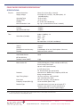
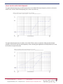
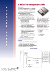
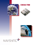
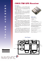
CW25-TIM GPS Receiver
P
R
O
D
U
C
T
B
R
I
Description
The CW25-TIM is a small OEM surface
mount GPS module that has been specifically
designed for use in synchronization and
timing applications.
The CW25-TIM has an on-board
programmable NCO oscillator that outputs a
synthesized frequency up to 30 MHz that is
steered by the GPS receiver.
The CW25-TIM has a self survey mode of
operation that allows the receiver to enter a
position hold mode to allow accurate timing
to be continued with only one satellite being
tracked.
Applications
•Synchronization
•Timing
•Indoor Timing
•GPS timing modules
(contact NavSync for further details)
The output frequency is highly accurate
and can achieve full PRC MTIE performance;
and can also track satellites and provide GPS
synchronization in weak signal areas such as
indoor applications. This reduces the need
for high antenna placement typically in many
environments.
A CW25 Demo board is available for evaluation of
the CW25 Receiver. A full kit contains the Demo
Board with mounted CW25-TIM or CW25-NAV,
RS232 serial Cable, Power Supply Adaptor (Region
Specific) with a 2.1 mm DC plug
and a 3m TNC Magnetic Patch Antenna.
To reduce costs, the CW25 Demo Board can be
purchased separately with a pick-and-choose
option for above accessories.
The CW25-TIM is an exceptionally small
surface mount package (25mm x 27mm x
4mm) with a highly integrated architecture that
requires the minimum of external components
allowing easy integration into host systems.
See CW25 Demo User Manual for more detailed
information on this unit.
Please contact NavSync for pricing information on
the full kit or individual items.
E
F
Block Diagram
ANT_SUPPLY
RF Block
RF_IN
TRIM/EXT_CLK
Bulletin
Revision
Date
NS18-PB
09
13 April 2010
Front
End
Filter
RF_3V3
DIG_1V8/+1V8_OUT
Regulator
& Reset
DIG_3V3
Regulator
Control
Emulation
RF25IC
BB25IC
Comms & I/O
Clock
IF
Filter
RTC &
EEPROM
NPOR
VBATT
2
IC
CW25-TIM GPS RECEIVER SPECIFICATIONS 1
SPECIFICATIONS 1
Physical
Module dimensions
Supply voltages
Operating Temp
Storage Temp
Humidity
Max Acceleration / Jerk
25mm (D) x 27mm (W) x 4.2mm (H)
3V3 (Digital I/O), 3V3 (RF), 1V8 (Core option), 3V
(Standby Battery)
-30°C to +80°C
-40°C to +85°C 2
5% to 95% non-condensing
4g / 1gs-1 (sustained for less than 5 seconds)
Sensitivity
-155dBm
-156dBm
-143dBm
Acquisition w/network assist
Tracking
Aquisition Stand Alone
Acquisition Hot Start with network assist
Time
Stand Alone (Outdoor)
Outdoor: <2s
Indoor (-148dBm): <5s
Cold: <45s
Warm: <38s
Hot:
<5s
Re-acquisition: <0.5s (90% confidence)
Accuracy Position: Outdoor / Indoor
Velocity
Latency
Raw Measurement Accuracy
Tracking
<5m rms / <50m rms
<0.05ms-1
<200ms
Pseudorange <0.3m rms, Carrier phase <5mm rms
Code and carrier coherent
Power
1 fix per second
Coma Mode Current
(RF3V3+DIG 3V3)
Standby Current (VBATT)
0.6W typically
10mA
1.5µA
Interfaces
Serial
Multi-function I/O
Protocols
1pps Timing Output
Event Input
Frequency Output (GPIO [0])
Receiver Type
3 UART ports, CMOS levels
1PPS and Frequency Output available on GPIO [0]
Event Counter/Timer Input
Up to 4 x GPIO (multi-function)
2 x LED Status Drive
I2C, External Clock (on special build)
Network Assist, NMEA 0183, Proprietary ASCII and binary message formats
10nS rms accuracy, <5nS resolution
User selectable pulse width
30ns rms accuracy, <10ns resolution
10 Hz to 30 MHz (CW25-TIM)
12 parallel channel x 32 taps up to 32 point FFT.
Channels, taps and FFT can be switched off to
minimize power or simulate simpler designs.
General
ARM 966E-S on a 0.18µ process at up to120 MHz.
Processor
Note: 1. The features listed above may require specific software builds and may not all be available in the initial release.
2. Please contact factory for other temperature options.
Copyright ©2010 Navsync Ltd.
NS18-PB CW25-TIM
All Rights Reserved
Rev 09 Date: 04/13/10
Specifications subject to change without notice.
CW25-TIM GPS MTIE PERFORMANCE
The graph below demonstrates the MTIE performance of the CW25-TIM output frequency relative to a Caesium
atomic clock, with the CW25-TIM operating with a clear view of the sky.
MTIE: Fo=10.00 MHz; Fs=1.000 Hz; 11/19/03 05:45:08 PM, 11/20/03 09:08:18 AM,
HP 53132A: Test 545; 10 MHz NCO: Samples: 55388; Gate: 1 s; Ref ch2: 10.00 MHz; TI/Time Data Only; TI 1>2
The graph below demonstrates the ability of the CW25-TIM to continue to provide a GPS disciplined output
frequency with the GPS aerial located completely inside a building (the degradation of MTIE performance is due
to the effects of signal multi-path)
MTIE: Fo=10.00 MHz; Fs=999.0 MHz; 2/12/04 02:38:18 PM, 2/12/04 05:50:27 PM,
HP 53132A: Test 589; CW25_indoor_tim; Samples: 11506; Gate: 1 s; Ref ch2: 10.00 MHz; TI/Time Data Only; TI 1>2
NS18-PB CW25-TIM
Rev 09 Copyright ©2010 Navsync Ltd.
All Rights Reserved
Date: 04/13/10
Specifications subject to change without notice.
CW25-TIM GPS Receiver
NavSync, Ltd. Europe
Bay 143
Shannon Industrial Estate
Shannon, Co. Clare, Ireland
Phone: +353 61 475 666
E-mail: [email protected]
North America
2111 Comprehensive Drive
Aurora, IL 60505, USA
Phone: 630.236.3026
E-mail: [email protected]
www.navsync.com