1
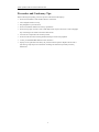
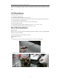
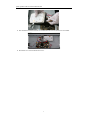
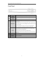
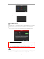
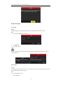
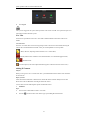
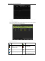
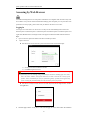
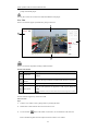
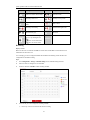
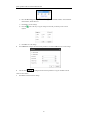
Network Video Recorder
Quick Operation Guide
Quick Operation Guide of Network Video Recorder
TABLE OF CONTENTS
NVR Installation .............................................................................................................................................. 6
Hard Disk Installation ..................................................................................................................................... 6
Front Panel ....................................................................................................................................................... 8
Rear Panel ........................................................................................................................................................ 9
Specifications .................................................................................................................................................. 10
Specifications ........................................................................................................................................... 10
HDD Storage Calculation Chart ................................................................................................................... 11
Menu Operation ............................................................................................................................................. 12
Menu Structure......................................................................................................................................... 12
Startup and Shutdown .............................................................................................................................. 12
Setting the Admin Password .................................................................................................................... 13
Login and Logout ..................................................................................................................................... 14
User Login ....................................................................................................................................... 14
User Logout ..................................................................................................................................... 14
Live View ................................................................................................................................................. 15
Adding IP Cameras .................................................................................................................................. 15
Recording ................................................................................................................................................. 18
Instant Recording ............................................................................................................................. 18
All-day Recording ............................................................................................................................ 18
Playback................................................................................................................................................... 18
Backup ..................................................................................................................................................... 20
VCA Detection ......................................................................................................................................... 21
VCA Search ............................................................................................................................................. 21
Accessing by Web Browser ............................................................................................................................ 23
Logging In................................................................................................................................................ 23
Live View ................................................................................................................................................. 24
Recording ................................................................................................................................................. 25
Playback................................................................................................................................................... 27
1
Quick Operation Guide of Network Video Recorder
About this Manual
This Manual is applicable to Network Video Recorder (NVR).
The Manual includes instructions for using and managing the product. Pictures, charts, images and all other
information hereinafter are for description and explanation only. The information contained in the Manual is
subject to change, without notice, due to firmware updates or other reasons. Please find the latest version in
the company website
Please use this user manual under the guidance of professionals.
Legal Disclaimer
REGARDING TO THE PRODUCT WITH INTERNET ACCESS, THE USE OF PRODUCT SHALL BE
WHOLLY AT YOUR OWN RISKS. OUR COMPANY SHALL NOT TAKE ANY RESPONSIBILITES
FOR ABNORMAL OPERATION, PRIVACY LEAKAGE OR OTHER DAMAGES RESULTING FROM
CYBER ATTACK, HACKER ATTACK, VIRUS INSPECTION, OR OTHER INTERNET SECURITY
RISKS; HOWEVER, OUR COMPANY WILL PROVIDE TIMELY TECHNICAL SUPPORT IF
REQUIRED.
SURVEILLANCE LAWS VARY BY JURISDICTION. PLEASE CHECK ALL RELEVANT LAWS IN
YOUR JURISDICTION BEFORE USING THIS PRODUCT IN ORDER TO ENSURE THAT YOUR USE
CONFORMS THE APPLICABLE LAW. OUR COMPANY SHALL NOT BE LIABLE IN THE EVENT
THAT THIS PRODUCT IS USED WITH ILLEGITIMATE PURPOSES.
IN THE EVENT OF ANY CONFLICTS BETWEEN THIS MANUAL AND THE APPLICABLE LAW,
THE LATER PREVAILS.
2
Quick Operation Guide of Network Video Recorder
Regulatory Information
FCC Information
FCC compliance: This equipment has been tested and found to comply with the limits for a digital device,
pursuant to part 15 of the FCC Rules. These limits are designed to provide reasonable protection against
harmful interference when the equipment is operated in a commercial environment. This equipment generates,
uses, and can radiate radio frequency energy and, if not installed and used in accordance with the instruction
manual, may cause harmful interference to radio communications. Operation of this equipment in a residential
area is likely to cause harmful interference in which case the user will be required to correct the interference at
his own expense.
FCC Conditions
This device complies with part 15 of the FCC Rules. Operation is subject to the following two conditions:
1. This device may not cause harmful interference.
2. This device must accept any interference received, including interference that may cause undesired
operation.
EU Conformity Statement
This product and - if applicable - the supplied accessories too are marked with "CE" and comply
therefore with the applicable harmonized European standards listed under the EMC Directive
2004/108/EC, the RoHS Directive 2011/65/EU.
2012/19/EU (WEEE directive): Products marked with this symbol cannot be disposed of as
unsorted municipal waste in the European Union. For proper recycling, return this product to
your local supplier upon the purchase of equivalent new equipment, or dispose of it at designated
collection points. For more information see: www.recyclethis.info
2006/66/EC (battery directive): This product contains a battery that cannot be disposed of as
unsorted municipal waste in the European Union. See the product documentation for specific
battery information. The battery is marked with this symbol, which may include lettering to
indicate cadmium (Cd), lead (Pb), or mercury (Hg). For proper recycling, return the battery to your supplier or
to a designated collection point. For more information see: www.recyclethis.info
Industry Canada ICES-003 Compliance
This device meets the CAN ICES-3 (B)/NMB-3(B) standards requirements.
3
Quick Operation Guide of Network Video Recorder
Safety Instruction
These instructions are intended to ensure that user can use the product correctly to avoid danger or property
loss.
The precaution measure is divided into “Warnings” and “Cautions”
Warnings: Serious injury or death may occur if any of the warnings are neglected.
Cautions: Injury or equipment damage may occur if any of the cautions are neglected.
Warnings
Follow
these
Cautions
Follow
to
these
safeguards to prevent serious
precautions
prevent
injury or death.
potential injury or material
damage.
Warnings
●
Proper configuration of all passwords and other security settings is the responsibility of the installer and/or
end-user.
●
In the use of the product, you must be in strict compliance with the electrical safety regulations of the
nation and region. Please refer to technical specifications for detailed information.
●
Input voltage should meet both the SELV (Safety Extra Low Voltage) and the Limited Power Source with
100~240 VAC or 12 VDC according to the IEC60950-1 standard. Please refer to technical specifications
for detailed information.
●
Do not connect several devices to one power adapter as adapter overload may cause over-heating or a fire
hazard.
●
Please make sure that the plug is firmly connected to the power socket.
If smoke, odor or noise rise from the device, turn off the power at once and unplug the power cable, and then
please contact the service center.
4
Quick Operation Guide of Network Video Recorder
Preventive and Cautionary Tips
Before connecting and operating your device, please be advised of the following tips:
•
•
•
•
•
Ensure unit is installed in a well-ventilated, dust-free environment.
Unit is designed for indoor use only.
Keep all liquids away from the device.
Ensure environmental conditions meet factory specifications.
Ensure unit is properly secured to a rack or shelf. Major shocks or jolts to the unit as a result of dropping it
may cause damage to the sensitive electronics within the unit.
•
•
•
•
Use the device in conjunction with an UPS if possible.
Power down the unit before connecting and disconnecting accessories and peripherals.
A factory recommended HDD should be used for this device.
Improper use or replacement of the battery may result in hazard of explosion. Replace with the same or
equivalent type only. Dispose of used batteries according to the instructions provided by the battery
manufacturer.
5
Quick Operation Guide of Network Video Recorder
Thank you for purchasing our product. If there is any question or request, please do not hesitate to contact
dealer.
NVR Installation
During the installation of the NVR:
1.
2.
3.
4.
5.
6.
7.
8.
Use brackets for rack mounting.
Ensure there is ample room for audio and video cables.
When routing cables, ensure that the bend radius of the cables are no less than five times than its diameter.
Connect both the alarm and RS-485 cable.
Allow at least 2cm (≈0.75-inch) of space between racks mounted devices.
Ensure the NVR is grounded.
Environmental temperature should be within the range of -10 ºC ~ 55 ºC, 14ºF ~ 131ºF.
Environmental humidity should be within the range of 10% ~ 90%.
Hard Disk Installation
Before you start:
Disconnect the power from the NVR before installing a hard disk drive (HDD). A factory recommended HDD
should be used for this installation.
Up to 2 SATA hard disks can be installed on your NVR.
Tools Required: Screwdriver.
Steps:
1. Remove the cover from the NVR by unfastening the screws on the rear and side panel.
2. Connect one end of the data cable to the motherboard of NVR and the other end to the HDD.
3. Connect the power cable to the HDD.
6
Quick Operation Guide of Network Video Recorder
4. Place the HDD on the bottom of the device and then fasten the screws on the bottom to fix the HDD.
5. Re-install the cover of the NVR and fasten screws.
7
Quick Operation Guide of Network Video Recorder
Front Panel
No.
Name
POWER
1
STATUS
Tx/Rx
Function Description
POWER indicator turns green when NVR is powered up.
STATUS indicator lights in red when data is being read from or written to
HDD.
Tx/Rx indictor blinks green when network connection is functioning properly.
The DIRECTION buttons are used to navigate between different fields and
items in menus.
In the Playback mode, the Up and Down button is used to speed up and slow
DIRECTION
down recorded video. The Left and Right button will select the next and
previous record files.
In Live View mode, these buttons can be used to cycle through channels.
2
In PTZ control mode, it can control the movement of the PTZ camera.
The ENTER button is used to confirm selection in any of the menu modes.
It can also be used to tick checkbox fields.
ENTER
In Playback mode, it can be used to play or pause the video.
In single-frame Playback mode, pressing the button will advance the video by a
single frame.
3
MENU
4
ESC
5
IR Receiver
6
USB Interface
Access the main menu interface.
Exit and back to the previous menu.
Receiver for IR remote.
Connects USB mouse or USB flash memory devices.
8
Quick Operation Guide of Network Video Recorder
Rear Panel
The rear panel vaires according to different models.
No.
Item
Description
1
Power Supply
DC 12V power supply.
2
Audio In
RCA connector for audio input.
3
HDMI Interface
HDMI video output connector.
4
LAN Network Interface
1 10 /100 /1000 Mbps self-adaptive Ethernet interface
5
Audio Out
RCA connector for audio output.
6
VGA Interface
DB9 connector for VGA output. Display local video output and menu.
7
USB Interface
Universal Serial Bus (USB) ports for additional devices such as USB
mouse and USB Hard Disk Drive (HDD).
8
Ground
Ground (needs to be connected when NVR starts up).
9
Power Switch
Switch for turning on/off the device.
9
Quick Operation Guide of Network Video Recorder
Specifications
Specifications
Model
4ch
8ch
16ch
8-ch
16-ch
Video/Audio
IP video input
4-ch
input
Two-way audio input
1-ch, RCA (2.0 Vp-p, 1KΩ)
Incoming bandwidth
40Mbps
Outgoing bandwidth
80Mbps
Remote connection
32
Recording resolution
6MP/5MP/3MP/1080P/UXGA/720P/VGA/4CIF/DCIF/2CIF/CIF/QCIF
Network
80Mbps
160Mbps
128
Main stream: 50 fps (P) / 60 fps (N)
Frame rate
Sub-stream: 50 fps (P) / 60 fps (N)
Video/Audio
HDMI/VGA output
1-ch, resolution:
1920 × 1080P /60Hz, 1600 × 1200 /60Hz, 1280 × 1024 /60Hz, 1280 × 720 /60Hz,
1024 × 768 /60Hz
Audio output
1-ch, RCA (Linear, 1kΩ)
Live view / Playback
resolution
6MP/5MP/3MP/1080P/UXGA/720P/VGA/4CIF/DCIF/2CIF/CIF/QCIF
Capability
4-ch@1080P
8-ch@720P,
6-ch@1080P
SATA
1 SATA interface for 1
HDD
2 SATA interfaces for 2 HDDs
Capacity
Up to 4TB for each disk
External
Network interface
1 RJ-45 10 /100 /1000 Mbps self-adaptive Ethernet interface
interface
USB interface
1 × USB 2.0 and 1 × USB 3.0
Power supply
12V DC
Consumption
(without hard disk)
≤ 10W
Working
temperature
-10 ºC ~ +55 ºC (+14 ºF~ + 131 ºF)
Working humidity
10 % ~ 90 %
Chassis
1U chassis
380 chassis
Dimensions
(W × D × H)
315 × 230 × 45 mm
(12.4" × 9.0" × 1.8")
380 × 290 × 48mm (15.0" ×11.4" × 1.9")
Weight
(without hard disk)
≤ 1 kg (2.2 lb)
≤ 1 kg (2.2 lb)
output
Decoding
Hard disk
Others
10
16-ch@4CIF,
12-ch@720P,
6-ch@1080P
Quick Operation Guide of Network Video Recorder
HDD Storage Calculation Chart
The following chart shows an estimation of storage space used based on recording at one channel for an hour
at a fixed bit rate.
Bit Rate
96K
128K
160K
192K
224K
256K
320K
384K
448K
512K
640K
768K
896K
1024K
1280K
1536K
1792K
2048K
Storage Used
42M
56M
70M
84M
98M
112M
140M
168M
196M
225M
281M
337M
393M
450M
562M
675M
787M
900M
4096K
1.8G
8192K
3.6G
16384K
7.2G
Please note that supplied values for storage space used is just for reference. The storage values in the chart are
estimated by formulas and may have some deviation from actual value.
11
Quick Operation Guide of Network Video Recorder
Menu Operation
Menu Structure
The menu structure is shown as follows. It vaires according to different models.
The RS-232 and Hot Spare are not available for this series.
Startup and Shutdown
Proper startup and shutdown procedures are crucial to expanding the life of the NVR.
To start your NVR:
Steps:
1.
Check the power supply is plugged into an electrical outlet. It is HIGHLY recommended that an
Uninterruptible Power Supply (UPS) be used in conjunction with the device. The Power indicator LED
on the front panel should be red, indicating the device gets the power supply
2.
Turn on the power switch on the rear panel if the device starts up for the first time. The Power indicator
LED should turn green indicating that the unit begins to start up.
After the device starting up, the wizard will guide you through the initial settings, including modifying
password, date and time settings, network settings, HDD initializing, and recording.
To shut down the NVR:
Steps:
1.
Enter the Shutdown menu.
Menu > Shutdown
12
Quick Operation Guide of Network Video Recorder
2.
Select the Shutdown button.
3.
Click the Yes button.
4.
Turn off the power switch on the rear panel when the attention pops up.
Setting the Admin Password
Purpose:
For the first-time access, you need to activate the device by setting an admin password. No operation is
allowed before activation. You can also activate the device via Web Browser, SADP or Client Software.
Steps:
1.
Input the same password in the text field of Create New Password and Confirm New Password.
STRONG PASSWORD RECOMMENDED– We highly recommend you create a strong
password of your own choosing (using a minimum of 8 characters, including upper case letters,
lower case letters, numbers, and special characters) in order to increase the security of your
product. And we recommend you reset your password regularly, especially in the high security
system, resetting the password monthly or weekly can better protect your product.
2.
Click OK to save the password and activate the device.
For the old version device, if you update it to the new version, the following dialog box will pop up once the
device starts up. You can click YES and follow the wizard to set a strong password.
13
Quick Operation Guide of Network Video Recorder
Login and Logout
User Login
Purpose:
If NVR has logged out, you must login the device before operating the menu and other functions.
Steps:
1.
Select the User Name in the dropdown list.
2.
Input Password.
3.
Click OK to log in.
The device gets locked for 60 seconds if the admin user performs 7 failed password attempts (5 attempts for
the guest/operator).
User Logout
Purpose:
After logging out, the monitor turns to the live view mode and if you want to do some operation, you need to
enter user name and password tog in again.
Steps:
1.
Enter the Shutdown menu.
Menu > Shutdown
14
Quick Operation Guide of Network Video Recorder
2.
Click Logout.
After you have logged out the system, menu operation on the screen is invalid. It is required to input a user
name and password to unlock the system.
Live View
Some icons are provided on screen in Live View mode to indicate different camera status. These icons
include:
Live View Icons
In the live view mode, there are icons at the upper-right corner of the screen for each channel, showing the
status of the record and alarm in the channel, so that you can find problems as soon as possible.
Alarm (video loss, tampering, motion detection, VCA or sensor alarm)
Record (manual record, continuous record, motion detection, VCA and alarm triggered record)
Alarm & Record
Event/Exception (event and exception information, appears at the lower-left corner of the screen.)
Adding IP Cameras
Purpose:
Before you can get a live view or record of the video, you should add the network cameras to the connection
list of the device.
Before you start:
Ensure the network connection is valid and correct, and the IP camera to add has already been activated.
Please refer to the User Manual for activating the inactive IP camera.
You can select one of the following three options to add the IP camera.
OPTION 1:
Steps:
1.
Click to select an idle window in the live view mode.
2.
Click the
icon in the center of the windw to pop up the adding IP camera interface.
15
Quick Operation Guide of Network Video Recorder
3.
Select the detected IP camera and click the Add button to add it directly, and you can click the Search
button to refresh the online IP camera manually.
Or you can choose to custom add the IP camera by editing the parameters in the corresponding textfiled
and then click the Add button to add it.
OPTION 2:
Steps:
1.
Select the Add IP Camera option from the right-click menu in live view mode or click Menu> Camera>
Camera to enter the IP camera management interface.
2.
The online cameras with same network segment will be detected and displayed in the camera list.
3.
Select the IP camera from the list and click the
button to add the camera. Or you can click the
One-touch Adding button to add all cameras from the list.
OPTION 3:
Steps:
1) On the IP Camera Management interface, click the Custom Adding button to pop up the Add IP
Camera (Custom) interface.
16
Quick Operation Guide of Network Video Recorder
2) You can edit the IP address, protocol, management port, and other information of the IP camera to
be added.
3) Click Add to add the camera.
For the successfully added IP cameras, the Security status shows the security level of the password of
camera: strong password, weak password and risk password.
Explanation of the icons
Icon
Explanation
Icon
Explanation
Add the detected IP camera.
Edit basic parameters of the camera
The camera is disconnected; you can
click the icon to get the exception
Delete the IP camera
information of camera.
Play the live video of the connected
Advanced settings of the camera.
camera.
Show the security status of the camera
Upgrade the connected IP camera.
Security
to be active/inactive or the password
strength (strong/medium/weak/risk)
17
Quick Operation Guide of Network Video Recorder
Recording
Before you start:
Make sure that the HDD has already been installed. If not, please install a HDD and initialize it. You can refer
to the user manual for detailed information.
Purpose:
Two kinds of record types are introduced in the following section, including Instant Record and All-day
Record. And for other record types, you may refer to the user manual for detailed information.
After rebooting all the manual records enabled are canceled.
Instant Recording
On the live view window of each channel, there is a quick setting toolbar which shows on the bottom of the
window when you click on it.
Click the
icon to enable the record, and the icon turns to
then the icon turns to
. And click
icon to disable the record,
.
All-day Recording
Steps:
1.
On the live view window, right lick the window and move the cursor to the Start Recording option,
and select Continuous Record or Motion Detection Record on your demand.
2.
And click the Yes button in the popup Attention message box to confirm the settings.
Then all the channels will start to record in the selected mode.
Playback
Play back the record files of a specific channel in the live view menu. Channel switch is supported.
Option 1:
Choose a channel under live view using the mouse and click the
button in the shortcut operation menu.
Only record files recorded during the past five minutes on this channel will be played back.
18
Quick Operation Guide of Network Video Recorder
Option 2:
Steps:
1.
Enter the Playback menu.
Mouse: right click a channel in live view mode and select Playback from the menu.
Under multi-screen live view, record files of the selected channel will be played back.
2.
Playback management.
The toolbar in the bottom part of Playback interface can be used to control playing process.
19
Quick Operation Guide of Network Video Recorder
Just check the channel or channels if you want to switch playback to another channel or execute
simultaneous playback of multiple channels.
Backup
Recorded files can be backed up to various devices, such as USB flash drives, USB HDDs or a DVD writer.
Steps:
1.
Enter Video Export interface.
Choose the channel(s) you want to back up and click on the Quick Export button.
2.
Enter Export interface, choose backup device and click Export button to start exporting.
3.
Check backup result.
20
Quick Operation Guide of Network Video Recorder
VCA Detection
Purpose:
The NVR supports the VCA detection alarm (face detection, line crossing detection and intrusion detection,
region entrance detection, region exiting detection, loitering detection, people gathering detection, fast
moving detection, parking detection, unattended baggage detection, object removal detection, audio loss
exception detection, sudden change of sound intensity detection, and defocus detection) sent by IP camera.
The VCA detection must be enabled and configured on the IP camera settings interface first.
Steps:
1. Enter VCA Alarm interface of Camera Management and select a camera you want to detect VCA alarm.
Menu > Camera > VCA
2.
Enable the VCA detection and configure the rule settings. Please refer to the User Manual for detailed
instructions.
VCA Search
The NVR supports the VCA search for the behavior analysis, face capture, people counting and heat map.
Face Search: Search the captured face picture results triggered by face detection.
Behavior Search: Search and view the behavior detection (including the line crossing detection, intrusion
detection, unattended baggage detection, etc.) results in pictures and video files.
People Counting: Calculate the number of people entered or exited from a certain configured area and show
in chart of daily/weekly/monthly/annual report.
Heat Map: Analyze the visit times and dwell time of customers in a configured area. The heat map is a
21
Quick Operation Guide of Network Video Recorder
graphical representation of data represented by colors.
22
Quick Operation Guide of Network Video Recorder
Accessing by Web Browser
You shall acknowledge that the use of the product with Internet access might be under network security risks.
For avoidance of any network attacks and information leakage, please strengthen your own protection. If the
product does not work properly, please contact with your dealer or the nearest service center.
Logging In
You can get access to the device via web browser. You may use one of the following listed web browsers:
Internet Explorer 6.0, Internet Explorer 7.0, Internet Explorer 8.0, Internet Explorer 9.0, Internet Explorer 10.0,
Apple Safari, Mozilla Firefox, and Google Chrome. The supported resolutions include 1024*768 and above.
Steps:
1.
2.
Open web browser, input the IP address of the device and then press Enter.
Login to the device.
If the device has not been activated, you need to activate the device first before login.
1)
Set the password for the admin user account.
2)
Click OK to login to the device.
STRONG PASSWORD RECOMMENDED– We highly recommend you create a strong
password of your own choosing (using a minimum of 8 characters, including upper case letters,
lower case letters, numbers, and special characters) in order to increase the security of your
product. And we recommend you reset your password regularly, especially in the high security
system, resetting the password monthly or weekly can better protect your product.
If the device is already activated, enter the user name and password in the login interface, and click
the Login button.
3.
Install the plug-in before viewing the live video and managing the camera. Please follow the installation
23
Quick Operation Guide of Network Video Recorder
prompts to install the plug-in.
You may have to close the web browser to finish the installation of the plug-in.
Live View
The live view interface appears by default when you log in the device.
The live view interface may differ according to different models.
Interface Introduction
No.
Name
1
Channel List
2
Live View
Window
Description
Displays the list of channels and the playing and recording status of each
channel.
Displays the image of channel, and multi-window division is supported.
3
Play Control Bar
Play control operations are supported.
4
PTZ Control
calling.
Pan, tilt, zoom operations are supported, as well as preset editing and
PTZ function can only be realized if the connected camera supports PTZ control.
The PTZ control is supported by certain series NVR.
Start Live View
Steps:
1.
In the live view window, select a playing window by clicking the mouse.
2.
Double click a camera from the device list to start the live view.
3.
You can click the
button on the toolbar to start the live view of all cameras on the device list.
Refer to the following table for the description of buttons on the live view window:
24
Quick Operation Guide of Network Video Recorder
Icon
Description
Icon
Select the window-division mode
/
Start/Stop all live view
/
Description
/
Capture pictures in the live view
Start/Stop all recording
/
Previous/Next page
/
Start/Stop two-way Audio
Adjust volume
mode
/
Open/Close audio
Enable/Disable digital zoom
Full screen
Select different stream type for
live view by clicking the icon
: live view in main stream;
: live view in sub stream;
Recording
Before you start
Make sure the device is connected with HDD or network disk, and the HDD or network disk has been
initialized for the first time to use.
Two recording types can be configured: Manual and Scheduled. The following section introduces the
configuration of scheduled recording.
Steps:
1.
Click Configuration > Storage > Schedule Settings to enter Schedule Settings interface.
2.
Select the camera to configure the record schedule.
3.
Check the checkbox of Enable to enable recording schedule.
4.
Choose the day in a week configure the recording schedule.
1)
Click a day to set the start time and end time for recording.
25
Quick Operation Guide of Network Video Recorder
2)
Select the Record Type for the period. The record type can be Schedule, Motion, Alarm, Motion &
Alarm, Motion | Alarm and Event.
3)
Click Save to save the settings.
4)
Click the
required.
5)
Click OK to save the settings.
icon of the day to copy the settings of current day to other days of the week if
5.
Click Advanced to configure advanced record parameters, and click the OK button to save the settings.
6.
You can click
to configure advanced record parameters to copy the schedule of current
camera to other cameras.
7.
Click Save to activate the above settings.
26
Quick Operation Guide of Network Video Recorder
Playback
The playback interface may differ according to different models.
Interface Introduction
No.
Name
Description
1
Channel List
Displays the list of channels and the playing status of each channel.
Playback
Displays the image of channel.
2
Window
3
Play Control Bar
Play control operations are supported.
4
Time Line
Displays the time bar and the records marked with different colors.
5
Playback Status
6
Calendar
Displays the playback status, including channel number and playback
speed.
You can select the date to play.
Start Playback
Steps:
1.
Click Playback on the menu bar to enter playback interface.
2.
Click the camera from the device list for playback.
3.
Select the date from the calendar and click Search.
4.
Click the Play button to play the video file searched on the current date.
5.
Use the buttons on the toolbar to operate in playback mode.
Button
Description
Button
/
Play/Pause
Stop
Speed down
Speed up
Play by single frame
Capture
27
Description
Quick Operation Guide of Network Video Recorder
Button
Description
Button
Stop all playback
/
Download
Start/Stop video clipping
/
Full screen
6.
Description
Open/Close audio
Reverse playback
You can drag the progress bar with the mouse to locate the exact playback point. You can also input the
time in the textbox
and click
button to locate the playback point.
The color of the video on the progress bar stands for the different video types.
28